EP0223077B1 - Lampenfassung für Leuchtstofflampen - Google Patents
Lampenfassung für Leuchtstofflampen Download PDFInfo
- Publication number
- EP0223077B1 EP0223077B1 EP86114380A EP86114380A EP0223077B1 EP 0223077 B1 EP0223077 B1 EP 0223077B1 EP 86114380 A EP86114380 A EP 86114380A EP 86114380 A EP86114380 A EP 86114380A EP 0223077 B1 EP0223077 B1 EP 0223077B1
- Authority
- EP
- European Patent Office
- Prior art keywords
- fluorescent lamp
- lamp holder
- lamp
- fluorescent
- spring force
- Prior art date
- Legal status (The legal status is an assumption and is not a legal conclusion. Google has not performed a legal analysis and makes no representation as to the accuracy of the status listed.)
- Expired - Lifetime
Links
- 238000003780 insertion Methods 0.000 claims description 13
- 230000037431 insertion Effects 0.000 claims description 13
- 230000014759 maintenance of location Effects 0.000 claims 1
- 238000006073 displacement reaction Methods 0.000 description 1
- 238000009434 installation Methods 0.000 description 1
- 238000000034 method Methods 0.000 description 1
- 239000002991 molded plastic Substances 0.000 description 1
- 239000004033 plastic Substances 0.000 description 1
Images
Classifications
-
- H—ELECTRICITY
- H01—ELECTRIC ELEMENTS
- H01R—ELECTRICALLY-CONDUCTIVE CONNECTIONS; STRUCTURAL ASSOCIATIONS OF A PLURALITY OF MUTUALLY-INSULATED ELECTRICAL CONNECTING ELEMENTS; COUPLING DEVICES; CURRENT COLLECTORS
- H01R33/00—Coupling devices specially adapted for supporting apparatus and having one part acting as a holder providing support and electrical connection via a counterpart which is structurally associated with the apparatus, e.g. lamp holders; Separate parts thereof
- H01R33/05—Two-pole devices
- H01R33/06—Two-pole devices with two current-carrying pins, blades or analogous contacts, having their axes parallel to each other
- H01R33/08—Two-pole devices with two current-carrying pins, blades or analogous contacts, having their axes parallel to each other for supporting tubular fluorescent lamp
- H01R33/0836—Two-pole devices with two current-carrying pins, blades or analogous contacts, having their axes parallel to each other for supporting tubular fluorescent lamp characterised by the lamp holding means
-
- H—ELECTRICITY
- H01—ELECTRIC ELEMENTS
- H01R—ELECTRICALLY-CONDUCTIVE CONNECTIONS; STRUCTURAL ASSOCIATIONS OF A PLURALITY OF MUTUALLY-INSULATED ELECTRICAL CONNECTING ELEMENTS; COUPLING DEVICES; CURRENT COLLECTORS
- H01R13/00—Details of coupling devices of the kinds covered by groups H01R12/70 or H01R24/00 - H01R33/00
- H01R13/62—Means for facilitating engagement or disengagement of coupling parts or for holding them in engagement
- H01R13/629—Additional means for facilitating engagement or disengagement of coupling parts, e.g. aligning or guiding means, levers, gas pressure electrical locking indicators, manufacturing tolerances
- H01R13/633—Additional means for facilitating engagement or disengagement of coupling parts, e.g. aligning or guiding means, levers, gas pressure electrical locking indicators, manufacturing tolerances for disengagement only
Definitions
- the invention relates to a lamp holder for fluorescent lamps, in particular for use in the passenger cabin of aircraft, according to the preamble of patent claim 1.
- the usual fluorescent lamps are used in their sockets by inserting the side contact pins into a guide slot and by pressing while rotating the lamps. This "screwing-in process" is not very comfortable. When installing such fluorescent lamps in the passenger cabin of aircraft with very limited space, the insertion of the fluorescent lamps is tedious.
- the invention proposes a version of the version according to the characterizing features of claim 1.
- the lamp holder With the inventive design of the lamp holder, it is possible to place the fluorescent lamp with its lateral contact pins on the insertion slots of the holder and only to press the fluorescent lamp into the holder.
- the contact pins are automatically adjusted into the appropriate insertion position and the lamp is automatically locked after being fully pressed in.
- the guide channel provided allows the fluorescent lamp to be automatically moved by spring force to the ejection position for removal from the socket, where it is then held securely.
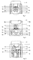
- a molded plastic part is designed as a socket 1 for one end of a fluorescent lamp.
- This has a guide channel 2, the walls 2a and 2b of which are at a distance which is only slightly larger than the diameter of the fluorescent lamp, so that it can be inserted smoothly into the guide channel.
- two resilient tabs 3a and 3b are provided, which have knobs 4a and 4b at their upper end, which grip behind the inserted lamp and also the lamp in the ejection position and prevent it from falling out.
- a fluorescent lamp inserted into the lamp holder is indicated in dashed lines in FIG. 1 in its normal working position.
- the insertion slots 5a and 5b for the contact pins of the fluorescent lamp are located next to one another in parallel and separated from one another by a web 6.
- the metallic contact pieces in the socket are not shown for the sake of clarity and since they are not necessary for understanding the invention.
- Retaining pins 7a and 7b protrude into the insertion slots, which are arranged on a locking plate 8 and can be moved sideways with this, against the spring force, in the drawing to the right.
- an unlocking button 9 is provided, which can be pressed into the version against a spring force.
- This unlocking button is mounted in guide rails 10a and 10b.
- the back of this release button is shown, the side facing the guide slots with their functional training is shown in dashed lines.
- the unlocking button has an inclined plane 11 which cooperates with a nose 12 with a correspondingly designed inclined plane on the locking plate 8.
- This locking plate 8 is laterally displaceable against the force of a resilient tab 19.
- the release button can be moved downward against the force of a spiral spring 13. To limit the lateral displacement of the locking plate 8, this carries a recess 14 in which a nose 15 of the Unlocking button 9 moves.
- FIG. 2 shows an ejection plate 16 with an insert 17 made of soft plastic, on which the fluorescent lamp rests against spring force when pressed into the working position.
- the spring (not shown in the drawing) below the ejection plate 16 is sufficient to push the fluorescent lamp upwards to the extent that it rests on the resilient tabs with the knobs 4a and 4b and is secured against falling out.
- FIG. 2 shows a screw socket 18 which serves to receive a screw for fastening the lamp socket.
- the lamp holder described has several advantages over the previously usual.
- the contact pins do not need to be inserted exactly into the guide slots, but instead center themselves when the lamp is inserted.
- the contact pins of the fluorescent lamp move the retaining pins 7a and 7b outward and reach the bottom of the insertion slots 5a and 5b. After the contact pins have passed the holding pins 7a and 7b, they return to their basic position shown in the drawing due to the spring force of the spring part 19 and lock the contact pins there. Simultaneously with the insertion of the fluorescent lamp, the ejection plate 16 was pressed down against a spring force.
- the fluorescent lamp If the fluorescent lamp is now to be removed, it is sufficient to press the release button 9, which pivots the retaining pins sideways via the inclined plane 11 and the knob 12 on the locking plate 8. Due to the spring force of the ejection plate 16, the fluorescent lamp is in the insertion slot which is now open at the top pressed up until it rests on the knobs 4a and 4b of the resilient tabs and is secured against falling out. The holding pins 7a and 7b remain pressed to the side by the contact pins of the fluorescent lamp even after the release button has been released. Now the fluorescent lamp can be easily removed from the holder by hand.
- the lampholder With the above-described design of the lampholder, it is therefore no longer necessary to screw it into the working position when inserting a fluorescent lamp, which is a significant advantage in particular in the very limited installation space in aircraft cabins.
- the inserted lamp is secured against falling out and is held against falling out even after unlocking in the ejection position, but can be easily removed by hand.
- the presence of a guide channel prevents possible misplacement of the fluorescent lamp, namely that both contact pins can get into an insertion slot.
Landscapes
- Fastening Of Light Sources Or Lamp Holders (AREA)
Description
- Die Erfindung betrifft eine Lampenfassung für Leuchtstofflampen, insbesondere zur Verwendung in der Passagierkabine von Flugzeugen, nach dem Oberbegriff des Patentanspruches 1.
- Die üblichen Leuchtstofflampen werden in ihre Fassungen durch Einstecken der seitlichen Kontaktstifte in einen Führungsschlitz und durch Druck bei gleichzeitigem Drehen der Lampen eingesetzt. Dieser "Eindrehvorgang" ist wenig komfortabel. Bei der Anbringung solcher Leuchtstofflampen in der Passagierkabine von Flugzeugen mit sehr beengten Platzverhältnissen ist das Einsetzen der Leuchtstofflampen mühsam.
- Es ist ferner bekannt, die Leuchtstofflampen bei Verwendung in Flugzeugen in ihren Fassungen durch einen Verriegelungshebel gegen Herausfallen zu sichern.
- Durch die deutsche Auslegeschrift DE-B-1 028 686 ist bereits eine Leuchtröhrenfassung mit einem oder mit zwei Einführungsschlitzen für Leuchtstofflampen bekannt. Für die Kontaktstifte der Leuchtstofflampen ist eine der Sicherungen in der Kontaktstellung dienende Verriegelungseinrichtung vorgesehen. Zur Entriegelung wird ein als Druckschieber ausgelegtes Auslöseglied betätigt.
- Ausgehend von dem vorgenannten Stand der Technik ist es Aufgabe der Erfindung, eine Fassung für Leuchtstofflampen der eingangs genannten Art anzugeben, bei welcher das Einsetzen der Leuchtstofflampen in die Fassung einfach und ohne Drehen möglich ist und eine selbsttätige Verriegelung erfolgt. Es soll ferner als weitere Ausbildungsmöglichkeit eine einfache Auswurfsicherung für die Leuchtstofflampe bei deren Entriegelung in der Fassung vorsehbar sein.
- Zur Lösung dieser Aufgabe schlägt die Erfindung eine Ausbildung der Fassung entsprechend den kennzeichnenden Merkmalen des Anspruches 1 vor.
- Mit der erfindungsgemäßen Ausbildung der Lampenfassung ist es möglich, die Leuchtstofflampe mit ihren seitlichen Kontaktstiften auf die Einführungsschlitze der Fassung zu legen und die Leuchtstofflampe lediglich in die Fassung einzudrücken. Es erfolgt dabei selbsttätig ein Justieren der Kontaktstifte in die geeignete Einführungslage sowie nach dem vollständigen Eindrücken ein selbsttätiges Verriegeln der Lampe. Gleichzeitig ist eine Auswurfsicherung für die Leuchtstofflampe nach deren Entriegelung vorhanden, wie sie insbesondere in Flugzeugen erwünscht ist.
- Der vorgesehene Führungskanal erlaubt es, daß die Leuchtstofflampe für eine Entnahme aus der Fassung selbsttätig durch Federkraft in die Auswurfstellung bewegt wird, wo sie dann sicher gehalten wird.
- Vorteilhafte Ausgestaltungen der Erfindung ergeben sich aus den weiteren Unteransprüchen.
- Nachfolgend soll die Erfindung anhand der Zeichnung an einem Ausführungsbeispiel näher beschrieben werden.
- Es zeigen:
- Fig. 1
- eine Vorderansicht der Lampenfassung mit den Einführungsschlitzen;
- Fig. 2
- eine Ansicht der Lampenfassung von oben;
- Fig. 3
- eine Ansicht der Lampenfassung von hinten, wobei der Entriegelungsknopf gestrichelt dargestellt ist.
- In der Zeichnung ist ein Kunststoffspritzteil als Fassung 1 für das eine Ende einer Leuchtstofflampe ausgebildet. Diese weist einen Führungskanal 2 auf, dessen Wände 2a und 2b einen Abstand besitzen, der nur unwesentlich größer als der Durchmesser der Leuchtstofflampe ist, so daß diese in den Führungskanal glatt eingeführt werden kann.
- Im Bereich des Führungskanals und einen Teil desselben bildend, sind zwei federnde Lappen 3a und 3b vorgesehen, welche an ihrem oberen Ende Noppen 4a und 4b aufweisen, die eingeschobene und auch die in Auswurfstellung befindliche Lampe hintergreifen und diese am Herausfallen hindern. Eine in die Lampenfassung eingesteckte Leuchtstofflampe ist in Figur 1 in ihrer normalen Arbeitsposition gestrichelt angedeutet.
- Im Gegensatz zu den üblichen Lampenfassungen sind die Einführungsschlitze 5a und 5b für die Kontaktstifte der Leuchtstofflampe parallel nebeneinanderliegend und durch einen Steg 6 voneinander getrennt. Die metallischen Kontaktstücke in der Fassung sind der Übersichtlichkeit halber und da für das Verständnis der Erfindung nicht erforderlich, nicht dargestellt. In die Einführungsschlitze ragen Haltestifte 7a und 7b, welche auf einer Verriegelungsplatte 8 angeordnet und mit dieser seitwärts, in der Zeichnung nach rechts, gegen eine Federkraft verschiebbar sind.
- In der Fassung 1 ist ein Entriegelungsknopf 9 vorgesehen, welcher gegen eine Federkraft in die Fassung eindrückbar ist. Dieser Entriegelungsknopf ist in Führungsschienen 10a und 10b gelagert. In Figur 3 ist die Rückseite dieses Entriegelungsknopfes dargestellt, wobei dessen den Führungsschlitzen zugewandte Seite mit ihrer Funktionsausbildung gestrichelt dargestellt ist.
Man erkennt, daß der Entriegelungsknopf eine schiefe Ebene 11 aufweist, welche mit einer Nase 12 mit einer entsprechend ausgebildeten schiefen Ebene auf der Verriegelungsplatte 8 zusammenarbeitet. Diese Verriegelungsplatte 8 ist gegen die Kraft eines federnden Lappens 19 seitlich verschiebbar. Der Entriegelungsknopf ist nach unten gegen die Kraft einer Spiralfeder 13 verschieblich. Zur Begrenzung der seitlichen Verschiebung der Verriegelungsplatte 8 trägt diese eine Ausnehmung 14, in welcher sich eine Nase 15 des Entriegelungsknopfes 9 bewegt. - In Figur 2 ist eine Auswurfplatte 16 mit einer aus weichem Kunststoff bestehenden Einlage 17 dargestellt, auf welcher die Leuchtstofflampe beim Eindrücken in Arbeitsstellung gegen Federkraft aufliegt. Bei Entriegelung der Leuchtstofflampe reicht die, in der Zeichnung nicht dargestellte, Feder unterhalb der Auswurfplatte 16 aus, die Leuchtstofflampe nach oben zu drücken, soweit, daß sie an den federnden Lappen mit den Noppen 4a und 4b anliegt und gegen Herausfallen gesichert ist.
- In Figur 2 ist schließlich noch eine Schraubenfassung 18 dargestellt, welche zur Aufnahme einer Schraube zur Befestigung der Lampenfassung dient.
- Die beschriebene Lampenfassung hat gegenüber den bisher üblichen mehrere Vorteile. Zum Einführen einer Leuchtstofflampe brauchen die Kontaktstifte nicht exakt in die Führungsschlitze eingelegt zu werden sondern zentrieren sich beim beliebigen Einlegen der Lampe von selbst. Dabei verschieben die Kontaktstifte der Leuchtstofflampe die Haltestifte 7a und 7b nach außen und gelangen an den Grund der Einführungsschlitze 5a und 5b. Nachdem die Kontaktstifte die Haltestifte 7a und 7b passiert haben, gelangen diese aufgrund der Federkraft des Federteiles 19 in ihre in der Zeichnung dargestellte Grundstellung zurück und verriegeln die Kontaktstifte dort. Gleichzeitig wurde mit dem Einführen der Leuchtstofflampe die Auswurfplatte 16 gegen eine Federkraft nach unten gedrückt. Soll nun die Leuchtstofflampe entnommen werden, so genügt ein Druck auf den Entriegelungsknopf 9, der über die schiefe Ebene 11 und die Noppe 12 an der Verriegelungsplatte 8 die Haltestifte seitwärts verschwenkt. Durch die Federkraft der Auswurfplatte 16 wird die Leuchtstofflampe in dem nun nach oben offenen Einführungsschlitz nach oben gedrückt, bis sie an den Noppen 4a und 4b der federnden Lappen anliegt und gegen Herausfallen gesichert ist. Dabei bleiben die Haltestifte 7a und 7b durch die Kontaktstifte der Leuchtstofflampe auch nach Loslassen des Entriegelungsknopfes zur Seite gedrückt. Nunmehr ist die Leuchtstofflampe von Hand leicht aus der Fassung entnehmbar.
- Mit der vorbeschriebenen Ausbildung der Fassung ist somit beim Einlegen einer Leuchtstofflampe kein Eindrehen derselben in die Arbeitsstellung mehr erforderlich, was insbesondere bei dem sehr beschränkten Einhauraum in Flugzeugkabinen ein wesentlicher Vorteil ist. Die eingelegte Lampe ist gegen Herausfallen gesichert und auch nach Entriegelung in der Auswurfstellung noch gegen Herausfallen gehalten, jedoch mit der Hand leicht entnehmbar.
Durch das Vorhandensein eines Führungskanals werden etwaige Fehlsteckungen der Leuchtstofflampe, nämlich daß beide Kontaktstifte in einen Einführungsschlitz gelangen können, vermieden.
Claims (4)
- Lampenfassung für Leuchtstofflampen, insbesondere zur Verwendung in der Passagierkabine von Flugzeugen, mit zwei nebeneinanderliegenden Einführungsschlitzen (5a,5b) und einer Verriegelungseinrichtung für die seitlichen Kontaktstifte der Leuchtstofflampe, bei welcher in die Einführungsschlitze (5a,5b) gegen Federkraft verschiebbare Haltestifte (7a,7b) ragen, auf die ein Entriegelungsknopf (9) einwirkt,
dadurch gekennzeichnet,
daß die Haltestifte (7a,7b) auf einer seitlich gegen Federkraft (19) verschiebbaren Verriegelungsplatte (8) angeordnet sind,
daß zur Führung der Leuchtstofflampe ein Führungskanal (2) parallel zu den Einführungsschlitzen (5a,5b) vorhanden ist, in dessen Bereich federnde Lappen (3a,3b) mit an ihren Enden angebrachten Noppen (4a,4b) parallel zu den Einführungsschlitzen (5a,5b) zur Halterung der entriegelten Leuchtstofflampe in Auswurfstellung vorgesehen sind,
und daß am Ende eine federnd gelagerte Auswurfplatte (16) für die Leuchtstofflampe eingerichtet ist. - Lampenfassung nach Anspruch 1,
dadurch gekennzeichnet,
daß der Entriegelungsknopf (9) in die Lampenfassung gegen Federkraft (13) eindrückbar ist und ein in Richtung parallel zu den Einführungsschlitzen (5a,5b) verschiebbares Fußteil mit einer schiefen Ebene (11) aufweist, welche mit einer entsprechend ausgebildeten schiefen Ebene (12) auf der Verriegelungsplatte (8) zusammenwirkt. - Lampenfassung nach Anspruch 2,
dadurch gekennzeichnet,
daß das Fußteil des Entriegelungsknopfes (9) gegen eine Feder (13) verschiebbar ist. - Lampenfassung nach Anspruch 1,
dadurch gekennzeichnet,
daß der Führungskanal (2) seitlich feste Wände (2a,2b) mit einem Abstand entsprechend dem Durchmesser der Leuchtstofflampe besitzt.
Applications Claiming Priority (2)
| Application Number | Priority Date | Filing Date | Title |
|---|---|---|---|
| DE3537601 | 1985-10-23 | ||
| DE19853537601 DE3537601A1 (de) | 1985-10-23 | 1985-10-23 | Lampenfassung fuer leuchtstofflampen |
Publications (3)
| Publication Number | Publication Date |
|---|---|
| EP0223077A2 EP0223077A2 (de) | 1987-05-27 |
| EP0223077A3 EP0223077A3 (en) | 1988-10-12 |
| EP0223077B1 true EP0223077B1 (de) | 1993-09-08 |
Family
ID=6284200
Family Applications (1)
| Application Number | Title | Priority Date | Filing Date |
|---|---|---|---|
| EP86114380A Expired - Lifetime EP0223077B1 (de) | 1985-10-23 | 1986-10-17 | Lampenfassung für Leuchtstofflampen |
Country Status (3)
| Country | Link |
|---|---|
| US (1) | US4795357A (de) |
| EP (1) | EP0223077B1 (de) |
| DE (2) | DE3537601A1 (de) |
Families Citing this family (11)
| Publication number | Priority date | Publication date | Assignee | Title |
|---|---|---|---|---|
| DE8801082U1 (de) * | 1988-01-29 | 1988-04-14 | Jörg, geb. Kirsch, Edith, 7702 Gottmadingen | Leuchtstoffröhrenleuchte |
| US5636919A (en) * | 1995-02-14 | 1997-06-10 | Grimes Aerospace Company | Lighting system |
| US5954535A (en) * | 1997-12-30 | 1999-09-21 | Aerospace Lighting Corporation | Quick release compact fluorescent lamp connector |
| US6871422B2 (en) * | 2000-10-17 | 2005-03-29 | Rhino Tuff, Inc. | Protective, orthotic insert for footwear |
| USD487252S1 (en) | 2002-01-22 | 2004-03-02 | Uv Doctor Llc | Ceramic ultraviolet lamp holder |
| DE10214922B4 (de) * | 2002-04-04 | 2005-03-10 | Vossloh Schwabe Gmbh | Fassung für elektrische Betriebsmittel |
| JP4621092B2 (ja) | 2005-08-12 | 2011-01-26 | 日本圧着端子製造株式会社 | 蛍光管の取付構造 |
| JP4728065B2 (ja) | 2005-08-12 | 2011-07-20 | 日本圧着端子製造株式会社 | 電気コネクタおよびこれを備える液晶表示装置 |
| KR101193686B1 (ko) * | 2005-08-29 | 2012-10-22 | 니혼앗짜쿠단시세이소 가부시키가이샤 | 전기 커넥터 및 액정 표시 장치 |
| DE102005049798A1 (de) * | 2005-10-14 | 2007-04-26 | Phoenix Contact Gmbh & Co. Kg | Elektrische Klemme für Leiterplatten |
| US7474043B2 (en) * | 2006-04-03 | 2009-01-06 | Osram Sylvania Inc. | Double-ended lamp socket with bulb removal feature |
Family Cites Families (5)
| Publication number | Priority date | Publication date | Assignee | Title |
|---|---|---|---|---|
| DE1050444B (de) * | 1959-02-12 | |||
| US2702377A (en) * | 1948-10-01 | 1955-02-15 | Vossloh Werke Gmbh | Holder with retaining means for electrical discharge tubes having pin contacts on their bases |
| DE1028686B (de) * | 1954-01-29 | 1958-04-24 | Lindner G M B H | Elektrische Leuchtroehrenfassung |
| DE1052566B (de) * | 1956-03-12 | 1959-03-12 | Vossloh Werke Gmbh | Fassung fuer Leuchtstofflampen mit Stiftsockeln |
| US3851295A (en) * | 1973-03-12 | 1974-11-26 | Bruce Ind Inc | Self-locking lampholder |
-
1985
- 1985-10-23 DE DE19853537601 patent/DE3537601A1/de active Granted
-
1986
- 1986-10-17 DE DE86114380T patent/DE3688998D1/de not_active Expired - Fee Related
- 1986-10-17 EP EP86114380A patent/EP0223077B1/de not_active Expired - Lifetime
-
1987
- 1987-12-29 US US07/139,182 patent/US4795357A/en not_active Expired - Fee Related
Also Published As
| Publication number | Publication date |
|---|---|
| EP0223077A3 (en) | 1988-10-12 |
| US4795357A (en) | 1989-01-03 |
| DE3537601C2 (de) | 1991-01-24 |
| DE3688998D1 (de) | 1993-10-14 |
| DE3537601A1 (de) | 1987-04-23 |
| EP0223077A2 (de) | 1987-05-27 |
Similar Documents
| Publication | Publication Date | Title |
|---|---|---|
| DE69803121T2 (de) | Verbinder mit Schnappbefestigung | |
| DE69510248T2 (de) | Nockenbetätigter Verbinder | |
| DE69416099T2 (de) | Selbsteinstellende Vorrichtung zum Einsetzen und Herausziehen von Leiterplatten | |
| DE2633972C3 (de) | Anordnung zum Verbinden zweier Bauteile | |
| EP0223077B1 (de) | Lampenfassung für Leuchtstofflampen | |
| DE3049336A1 (de) | Stecker und gegenstecker fuer die verbindung von elektrischen leitungen | |
| DE3816036C2 (de) | ||
| DE19840726A1 (de) | Elektrischer Steckverbinder | |
| DE1590311A1 (de) | Mehrpolige elektrische Steckvorrichtung | |
| WO2002027373A9 (de) | Kupplungseinrichtung für glasfaserverbinder | |
| DE3015138A1 (de) | Verriegelbarer steckverbinder | |
| DE102019123884A1 (de) | Steckverbinder und Stecksystem | |
| EP0465883A1 (de) | Elektrische Anschlussklemme zum Befestigen auf einer Tragschiene | |
| EP0446317A1 (de) | Leuchtenraster. | |
| DE3813948A1 (de) | Isoliergehaeuse fuer eine flachsteckhuelse | |
| EP0404988A1 (de) | Bezeichnungsträger für elektrische Leiter | |
| EP1354375A1 (de) | Sicherheitselement für steckdose | |
| DE10054739C2 (de) | Anordnung einer Einbauleuchte | |
| DE3744580C2 (de) | Fassung für einseitig gesockelte Lampen | |
| EP0197376A2 (de) | Sockel für Bauelement | |
| DE3146743C2 (de) | Leuchtenkörper für rohrförmige Entladungslampen | |
| DE102024126124A1 (de) | Leiteranschlussklemme zum Anschließen wenigstens eines elektrischen Leiters | |
| DE1765826A1 (de) | Beruehrungssichere Steckdose | |
| DE202024100272U1 (de) | Elektrisches Modul zum Anschließen an eine Tragschiene mit einem Tragschienenprofil | |
| DE102024126133A1 (de) | Federkraftklemmanschluss und Leiteranschlussklemme |
Legal Events
| Date | Code | Title | Description |
|---|---|---|---|
| PUAI | Public reference made under article 153(3) epc to a published international application that has entered the european phase |
Free format text: ORIGINAL CODE: 0009012 |
|
| AK | Designated contracting states |
Kind code of ref document: A2 Designated state(s): DE FR GB NL |
|
| PUAL | Search report despatched |
Free format text: ORIGINAL CODE: 0009013 |
|
| AK | Designated contracting states |
Kind code of ref document: A3 Designated state(s): DE FR GB NL |
|
| 17P | Request for examination filed |
Effective date: 19881202 |
|
| 17Q | First examination report despatched |
Effective date: 19911217 |
|
| GRAA | (expected) grant |
Free format text: ORIGINAL CODE: 0009210 |
|
| AK | Designated contracting states |
Kind code of ref document: B1 Designated state(s): DE FR GB NL |
|
| REF | Corresponds to: |
Ref document number: 3688998 Country of ref document: DE Date of ref document: 19931014 |
|
| GBT | Gb: translation of ep patent filed (gb section 77(6)(a)/1977) |
Effective date: 19931011 |
|
| ET | Fr: translation filed | ||
| PLBE | No opposition filed within time limit |
Free format text: ORIGINAL CODE: 0009261 |
|
| STAA | Information on the status of an ep patent application or granted ep patent |
Free format text: STATUS: NO OPPOSITION FILED WITHIN TIME LIMIT |
|
| 26N | No opposition filed | ||
| PGFP | Annual fee paid to national office [announced via postgrant information from national office to epo] |
Ref country code: FR Payment date: 19950828 Year of fee payment: 10 |
|
| PGFP | Annual fee paid to national office [announced via postgrant information from national office to epo] |
Ref country code: NL Payment date: 19951027 Year of fee payment: 10 |
|
| PGFP | Annual fee paid to national office [announced via postgrant information from national office to epo] |
Ref country code: GB Payment date: 19961118 Year of fee payment: 11 |
|
| PG25 | Lapsed in a contracting state [announced via postgrant information from national office to epo] |
Ref country code: NL Effective date: 19970501 |
|
| PG25 | Lapsed in a contracting state [announced via postgrant information from national office to epo] |
Ref country code: FR Effective date: 19970630 |
|
| NLV4 | Nl: lapsed or anulled due to non-payment of the annual fee |
Effective date: 19970501 |
|
| REG | Reference to a national code |
Ref country code: FR Ref legal event code: ST |
|
| PG25 | Lapsed in a contracting state [announced via postgrant information from national office to epo] |
Ref country code: GB Free format text: LAPSE BECAUSE OF NON-PAYMENT OF DUE FEES Effective date: 19971017 |
|
| GBPC | Gb: european patent ceased through non-payment of renewal fee |
Effective date: 19971017 |
|
| PGFP | Annual fee paid to national office [announced via postgrant information from national office to epo] |
Ref country code: DE Payment date: 19981215 Year of fee payment: 13 |
|
| PG25 | Lapsed in a contracting state [announced via postgrant information from national office to epo] |
Ref country code: DE Free format text: LAPSE BECAUSE OF NON-PAYMENT OF DUE FEES Effective date: 20000801 |