EP0223089A1 - Staubsauger mit einem im Staubraum eingesetzten Filterbeutel - Google Patents
Staubsauger mit einem im Staubraum eingesetzten Filterbeutel Download PDFInfo
- Publication number
- EP0223089A1 EP0223089A1 EP86114563A EP86114563A EP0223089A1 EP 0223089 A1 EP0223089 A1 EP 0223089A1 EP 86114563 A EP86114563 A EP 86114563A EP 86114563 A EP86114563 A EP 86114563A EP 0223089 A1 EP0223089 A1 EP 0223089A1
- Authority
- EP
- European Patent Office
- Prior art keywords
- cover
- vacuum cleaner
- dust chamber
- holding plate
- bevel
- Prior art date
- Legal status (The legal status is an assumption and is not a legal conclusion. Google has not performed a legal analysis and makes no representation as to the accuracy of the status listed.)
- Granted
Links
- 239000000428 dust Substances 0.000 title claims abstract description 20
- 230000007704 transition Effects 0.000 claims description 3
- 238000005452 bending Methods 0.000 abstract description 3
- 230000002028 premature Effects 0.000 description 1
Images
Classifications
-
- A—HUMAN NECESSITIES
- A47—FURNITURE; DOMESTIC ARTICLES OR APPLIANCES; COFFEE MILLS; SPICE MILLS; SUCTION CLEANERS IN GENERAL
- A47L—DOMESTIC WASHING OR CLEANING; SUCTION CLEANERS IN GENERAL
- A47L9/00—Details or accessories of suction cleaners, e.g. mechanical means for controlling the suction or for effecting pulsating action; Storing devices specially adapted to suction cleaners or parts thereof; Carrying-vehicles specially adapted for suction cleaners
- A47L9/10—Filters; Dust separators; Dust removal; Automatic exchange of filters
- A47L9/14—Bags or the like; Rigid filtering receptacles; Attachment of, or closures for, bags or receptacles
- A47L9/1427—Means for mounting or attaching bags or filtering receptacles in suction cleaners; Adapters
- A47L9/1436—Connecting plates, e.g. collars, end closures
-
- A—HUMAN NECESSITIES
- A47—FURNITURE; DOMESTIC ARTICLES OR APPLIANCES; COFFEE MILLS; SPICE MILLS; SUCTION CLEANERS IN GENERAL
- A47L—DOMESTIC WASHING OR CLEANING; SUCTION CLEANERS IN GENERAL
- A47L9/00—Details or accessories of suction cleaners, e.g. mechanical means for controlling the suction or for effecting pulsating action; Storing devices specially adapted to suction cleaners or parts thereof; Carrying-vehicles specially adapted for suction cleaners
- A47L9/10—Filters; Dust separators; Dust removal; Automatic exchange of filters
- A47L9/14—Bags or the like; Rigid filtering receptacles; Attachment of, or closures for, bags or receptacles
- A47L9/1427—Means for mounting or attaching bags or filtering receptacles in suction cleaners; Adapters
Definitions
- the invention relates to a vacuum cleaner with a filter bag used in the dust chamber, which has a rigid holding plate, which is inserted into a guide provided on the vacuum cleaner housing and bears against a suction nozzle opening into the dust chamber, on which holding plate, furthermore, at a distance from its upper boundary edge in the position of use A kink groove is formed, in which the vacuum cleaner projects the upper boundary edge of the holding plate into the pivoting path of a slant provided on the lid closing the dust chamber, which slides over the boundary edge when the lid is closed and which is delimited by the kink groove and bent towards the dust chamber.
- GB-A-1 211 782 also discloses a vacuum cleaner in which the filter bag is provided with a rigid connecting flange. With this connection flange, the filter bag is inserted into a wide guide of the vacuum cleaner housing. As a result of the wide leadership the connecting flange assumes an inclined position in which its inlet opening does not abut the suction nozzle provided on the vacuum cleaner housing. The connection flange is pressed against the suction nozzle when the dust chamber cover is closed.
- a pressure stop is provided on the cover, which, when the cover is closed, strikes with its oblique leading edge on a nose formed on the rigid connection flange and thereby swivels the connection flange into its operating position, in which the inlet opening then lies tightly against the suction nozzle.
- the invention has for its object to provide a vacuum cleaner of the type described in such a way that both an automatic buckling of the strip delimited on the holding plate when closing the lid and an additional support of the holding plate against the suction nozzle after closing the lid can be achieved.
- the object is achieved according to the invention in that a continuous, arc-shaped transition to a counter slope is provided on the cover to the slope, on which the upper boundary edge is supported when the cover is closed.
- the bevel hits the upper boundary edge of the holding plate.
- the slope has such an inclination that it slides over the boundary edge when the cover is closed further, thereby kinking the strip towards the dust chamber.
- the boundary edge can slide to counter-slopes without the risk of premature snagging.
- the counter bevel is designed in its position and in its steepness so that the upper boundary edge as a result when the lid is completely closed the steepness of the counter bevels does not slide further along it, but remains in its supported position by self-locking on the counter bevels. As a result, a pressure force is exerted by the counter bevel on the holding plate, which holds it securely in contact with the suction nozzle.
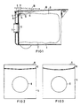
- a filter bag 3 is inserted in the dust chamber 2 .
- the filter bag 3 is connected to a rigid holding plate 4, which is inserted into a guide 5 provided on the vacuum cleaner housing 1.
- the holding plate 4 has an inlet opening 6 with which it bears against a suction nozzle 7 provided on the vacuum cleaner housing 1.
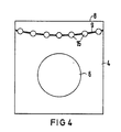
- the holding plate 4 has a kink groove 9 at a distance from its upper boundary edge 8.
- the kink groove 9 advantageously runs in a roof or arc shape, so that it has its greatest distance from the upper boundary edge 8 in the middle of the holding plate 4.
- Two ribs 11 are formed on the cover 10 closing the dust chamber 2 at a lateral distance from one another.
- the ribs 11 have a recess 14 delimited by a bevel 12 and a counter bevel 13.
- the recess 14 is arranged such that its bevel 12 strikes the upper boundary edge 8 of the holding plate 4 when the cover 10 is closed.
- the slope of the bevel 12 is dimensioned such that when the cover 10 is closed further it slides over the upper boundary edge 8 and thereby bends the strip delimited by the crease groove 9 towards the dust space.
- the upper boundary edge finally meets the counter bevels 13, the steepness of which is selected so that the boundary edge jams against the counter bevel 13 and thus bears against the latter when the cover 10 is closed.
- a pressure force is exerted on the holding plate 4 in the direction of the suction nozzle 7, so that the holding plate 4 lies securely on the suction nozzle 7.
- Fig. 1 the position of the cover 10 is shown in dashed lines when it hits the upper boundary edge 8 of the holding plate 4.
- the position of the bent strip when the cover 10 is completely closed is illustrated with solid lines.
Landscapes
- Engineering & Computer Science (AREA)
- Mechanical Engineering (AREA)
- Filters For Electric Vacuum Cleaners (AREA)
Abstract
Description
- Die Erfindung betrifft einen Staubsauger mit einem im Staubraum eingesetzten Filterbeutel, der eine steife Halteplatte aufweist, die in eine am Staubsaugergehäuse vorgesehene Führung eingesteckt ist und an einem in den Staubraum mündenden Saugstutzen anliegt, an welcher Halteplatte ferner in Abstand zu deren in der Gebrauchslage oberen Begrenzungsrand eine Knickrille ausgebildet ist, bei welchem Staubsauger der obere Begrenzungsrand der Halteplatte in den Verschwenkweg einer an dem den Staubraum verschließenden Deckel vorgesehenen, beim Schließen des Deckels über den Begrenzungsrand gleitenden und den durch die Knickrille abgegrenzten Streifen zum Staubraum hin umknickenden Schräge ragt.
- Ein solcher Staubsauger ist durch das DE-GM 84 27 471 bekannt. Durch das Umknicken des durch die Knickrille abgegrenzten Streifens der Halteplatte wird zwar eine Erhöhung der Steifigkeit der Halteplatte erreicht, jedoch ist dadurch allein noch nicht in allen Fällen eine sichere Anlage der Halteplatte am Saugstutzen gewährleistet.
- Durch die GB-A-1 211 782 ist ferner ein Staubsauger bekannt, bei dem der Filterbeutel mit einem starren Anschlußflansch versehen ist. Mit diesem Anschlußflansch wird der Filterbeutel in eine weite Führung des Staubsaugergehäuses eingelegt. Infolge der weiten Führung nimmt der Anschlußflansch eine Schräglage ein, in der er mit seiner Einlaßöffnung nicht an dem am Staubsaugergehäuse vorgesehenen Saugstutzen anliegt. Das Andrücken des Anschlußflansches an den Saugstutzen wird beim Schließen des Staubraumdeckels selbsttätig bewirkt. Hierzu ist an dem Deckel ein Druckanschlag vorgesehen, der beim Schließen des Deckels mit seiner schrägen Anlaufkante auf eine an dem starren Anschlußflansch ausgebildete Nase auftrifft und dadurch den Anschlußflansch in seine Betriebslage schwenkt, in der die Einlaßöffnung dann dicht an dem Saugstutzen anliegt.
- Demgegenüber liegt der Erfindung die Aufgabe zugrunde, einen Staubsauger der eingangs beschriebenen Art so auszubilden, daß sowohl ein selbsttätiges Umknicken des an der Halteplatte abgegrenzten Streifens beim Schließen des Deckels als auch eine zusätzliche Abstützung der Halteplatte gegen den Saugstutzen nach dem Schließen des Deckels erreicht werden.
- Die Lösung der gestellten Aufgabe gelingt nach der Erfindung dadurch, daß an dem Deckel an die Schräge anschließend ein kontinuierlicher, bogenförmiger Übergang zu einer Gegenschräge vorgesehen ist, an der der obere Begrenzungsrand bei geschlossenem Deckel abgestützt ist. Beim Schließen des Deckels trifft die Schräge auf den oberen Begrenzungsrand der Halteplatte. Die Schräge hat eine solche Neigung, daß sie beim weiteren Schließen des Deckels über den Begrenzungsrand hinweggleitet und dadurch den Streifen zum Staubraum hin abknickt. Infolge des kontinuierlichen, bogenförmigen Überganges kann der Begrenzungsrand ohne die Gefahr des vorzeitigen Hängenbleibens bis zu Gegenschräge gleiten. Die Gegenschräge ist in ihrer Lage und in ihrer Steilheit so ausgebildet, daß der obere Begrenzungsrand bei vollständig geschlossenem Deckel infolge der Steilheit der Gegenschräge nicht weiter an dieser entlang gleitet, sondern durch Selbsthemmung an der Gegenschräge in seiner abgestützten Stellung verbleibt. Hierdurch wird von der Gegenschräge eine Andrückkraft auf die Halteplatte ausgeübt, die diese sicher in Anlage an dem Saugstutzen hält.
- Dadurch, daß an dem Deckel zwei die Schräge und Gegenschräge enthaltende Rippen in seitlichem Abstand zueinander vorgesehen sind, wird nicht nur ein gleichmäßiges Andrücken der Halteplatte erreicht, sondern auch verhindert, daß der Deckel des Staubraumes bei nicht ordnungsgemäß in die Führung eingesetzter Halteplatte geschlossen werden kann. Ist nämlich die Halteplatte versehentlich nur auf einer Seite in die Führung eingesteckt, dann hat dies eine leichte Schiefstellung der Halteplatte gegenüber ihrer ordnungsgemäßen Gebrauchslage zur Folge. Der obere Begrenzungsrand trifft dadurch an unterschiedlichen Stellen auf die Schrägen der beiden seitlich beabstandeten Rippen, sodaß der Streifen nicht umgeknickt und der Deckel somit nicht geschlossen werden kann.
- Anhand eines in der Zeichnung dargestellten Ausführungsbeispieles wird der Anmeldungsgegenstand nachfolgend näher beschrieben. Es zeigt:
- Fig. 1 einen Staubsauger mit einem im Staubraum eingesetzten Filterbeutel,
- Fig. 2 eine Draufsicht einer Halteplatte mit dreieckförmiger Knickrille,
- Fig. 3 eine Draufsicht einer Halteplatte mit bogenförmiger Knickrille,
- Fig. 4 eine Draufsicht einer Halteplatte, bei der die Knickrille perforiert ist.
- Mit 1 ist ein Staubsaugergehäuse bezeichnet, in dessen Staubraum 2 ein Filterbeutel 3 eingesetzt ist. Der Filterbeutel 3 ist mit einer steifen Halteplatte 4 verbunden, die in eine an dem Staubsaugergehäuse 1 vorgesehene Führung 5 eingesteckt ist. Die Halteplatte 4 weist eine Einlaßöffnung 6 auf, mit der sie an einem am Staubsaugergehäuse 1 vorgesehenen Saugstutzen 7 anliegt.
- Wie aus den Fig. 2, 3 und 4 zu ersehen ist, weist die Halteplatte 4 in Abstand zu ihrem oberen Begrenzungsrand 8 eine Knickrille 9 auf. Die Knickrille 9 verläuft vorteilhafterweise dach- oder bogenförmig, sodaß sie in der Mitte der Halteplatte 4 ihren größten Abstand zu dem oberen Begrenzungsrand 8 hat.
- An dem den Staubraum 2 verschließenden Deckel 10 sind in seitlichem Abstand zueinander zwei Rippen 11 angeformt. Die Rippen 11 weisen eine durch eine Schräge 12 und eine Gegenschräge 13 begrenzte Ausnehmung 14 auf. Die Ausnehmung 14 ist so angeordnet, daß deren Schräge 12 beim Schließen des Deckels 10 auf den oberen Begrenzungsrand 8 der Halteplatte 4 auftrifft. Die Steigung der Schräge 12 ist so bemessen, daß diese beim weiteren Schließen des Deckels 10 über den oberen Begrenzungsrand 8 hinweggleitet und dadurch den durch die Knickrille 9 abgegrenzten Streifen zum Staubraum hin umknickt. Im weiteren Verlauf des Schließens des Deckels 10 trifft der obere Begrenzungsrand schließlich auf die Gegenschräge 13, deren Steilheit so gewählt ist, daß der Begrenzungsrand an der Gegenschräge 13 verklemmt und somit bei geschlossenem Deckel 10 an dieser anliegt. Hierdurch wird auf die Halteplatte 4 eine Andrückkraft in Richtung auf den Saugstutzen 7 ausgeübt, sodaß die Halteplatte 4 sicher an dem Saugstutzen 7 anliegt.
- In der Fig. 1 ist mit gestrichelten Linien die Stellung des Deckels 10 beim Auftreffen auf den oberen Begrenzungsrand 8 der Halteplatte 4 dargestellt. Mit voll ausgezogenen Linien ist die Lage des abgeknickten Streifens bei vollständig geschlossenem Deckel 10 verdeutlicht.
- Infolge des dach- oder bogenförmigen Verlaufs der Knickrille 9 ergibt sich in der Mitte der Halteplatte 4 eine höhere Andrückkraft, sodaß die Halteplatte 4 im Bereich ihrer Einlaßöffnung 6 verstärkt gegen den Saugstutzen 7 gedrückt wird. Ist die Knickrille nach Art einer Perforierung mit Löchern 15 versehen, dann wird hiedurch das Umknicken des durch die Knickrille 9 abgegrenzten Streifens erleichtert, ohne daß die für das Andrücken der Halteplatte 4 notwendige Steifigkeit des Streifens vermindert wird.
Claims (4)
dadurch gekennzeichnet,
daß an dem Deckel (10) an die Schräge (12) anschließend ein kontinuierlicher, bogenförmiger Übergang zu einer Gegenschräge (13) vorgesehen ist, an der der obere Begrenzungsrand (8) bei geschlossenem Deckel (10) abgestützt ist.
dadurch gekennzeichnet,
daß an dem Deckel (10) zwei die Schräge (12) und Gegenschräge (13) enthaltende Rippen (11) in seitlichem Abstand zueinander vorgesehen sind.
dadurch gekennzeichnet,
daß die Knickrille (9) dach- oder bogenförmig ausgebildet ist, wobei die Dachspitze bzw. der Scheitelpunkt des Bogens zur Einlaßöffnung (6) der Halteplatte (4) weist.
dadurch gekennzeichnet,
daß die Knickrille (9) nach Art einer Perforierung mit Löchern (15) versehen ist.
Applications Claiming Priority (2)
| Application Number | Priority Date | Filing Date | Title |
|---|---|---|---|
| DE8531131U DE8531131U1 (de) | 1985-11-04 | 1985-11-04 | Staubsauger mit einem, im Staubraum eingesetzten Filterbeutel |
| DE8531131U | 1985-11-04 |
Publications (2)
| Publication Number | Publication Date |
|---|---|
| EP0223089A1 true EP0223089A1 (de) | 1987-05-27 |
| EP0223089B1 EP0223089B1 (de) | 1989-06-14 |
Family
ID=6786905
Family Applications (1)
| Application Number | Title | Priority Date | Filing Date |
|---|---|---|---|
| EP86114563A Expired EP0223089B1 (de) | 1985-11-04 | 1986-10-21 | Staubsauger mit einem im Staubraum eingesetzten Filterbeutel |
Country Status (2)
| Country | Link |
|---|---|
| EP (1) | EP0223089B1 (de) |
| DE (2) | DE8531131U1 (de) |
Cited By (2)
| Publication number | Priority date | Publication date | Assignee | Title |
|---|---|---|---|---|
| EP0468065A1 (de) * | 1990-07-23 | 1992-01-29 | Siemens Aktiengesellschaft | Staubsauger mit einer in seinen Staubraum einsetzbaren Filterkassette |
| SE541105C2 (en) * | 2016-05-09 | 2019-04-09 | Electrolux Ab | Dust Container for a vacuum cleaner |
Citations (4)
| Publication number | Priority date | Publication date | Assignee | Title |
|---|---|---|---|---|
| GB1211782A (en) * | 1967-09-05 | 1970-11-11 | Licentia Gmbh | Improvements in vacuum cleaners |
| DE2649239A1 (de) * | 1976-10-29 | 1978-05-11 | Miele & Cie | Einrichtung zum befestigen eines filterbeutels an einer staubfoerderleitung |
| GB2097284A (en) * | 1981-04-28 | 1982-11-03 | Vorwerk Co Interholding | Retaining device for a filter bag of a suction cleaner |
| EP0178607A2 (de) * | 1984-10-16 | 1986-04-23 | Progress Elektrogeräte GmbH | Staubsaugergehäuse und Staubbeutel |
-
1985
- 1985-11-04 DE DE8531131U patent/DE8531131U1/de not_active Expired
-
1986
- 1986-10-21 DE DE8686114563T patent/DE3663880D1/de not_active Expired
- 1986-10-21 EP EP86114563A patent/EP0223089B1/de not_active Expired
Patent Citations (4)
| Publication number | Priority date | Publication date | Assignee | Title |
|---|---|---|---|---|
| GB1211782A (en) * | 1967-09-05 | 1970-11-11 | Licentia Gmbh | Improvements in vacuum cleaners |
| DE2649239A1 (de) * | 1976-10-29 | 1978-05-11 | Miele & Cie | Einrichtung zum befestigen eines filterbeutels an einer staubfoerderleitung |
| GB2097284A (en) * | 1981-04-28 | 1982-11-03 | Vorwerk Co Interholding | Retaining device for a filter bag of a suction cleaner |
| EP0178607A2 (de) * | 1984-10-16 | 1986-04-23 | Progress Elektrogeräte GmbH | Staubsaugergehäuse und Staubbeutel |
Cited By (2)
| Publication number | Priority date | Publication date | Assignee | Title |
|---|---|---|---|---|
| EP0468065A1 (de) * | 1990-07-23 | 1992-01-29 | Siemens Aktiengesellschaft | Staubsauger mit einer in seinen Staubraum einsetzbaren Filterkassette |
| SE541105C2 (en) * | 2016-05-09 | 2019-04-09 | Electrolux Ab | Dust Container for a vacuum cleaner |
Also Published As
| Publication number | Publication date |
|---|---|
| DE8531131U1 (de) | 1987-03-05 |
| DE3663880D1 (en) | 1989-07-20 |
| EP0223089B1 (de) | 1989-06-14 |
Similar Documents
| Publication | Publication Date | Title |
|---|---|---|
| DE3842222C2 (de) | ||
| DE3132114C2 (de) | ||
| EP0453906A1 (de) | Rasierapparatekopf, insbesondere Rasierklingeneinheit, eines Nassrasierapparates | |
| DE3049336A1 (de) | Stecker und gegenstecker fuer die verbindung von elektrischen leitungen | |
| EP0045036A1 (de) | Staubsauger mit einem den Staubraum abschliessenden Deckel | |
| EP0223089B1 (de) | Staubsauger mit einem im Staubraum eingesetzten Filterbeutel | |
| EP0409038B1 (de) | Staubsaugerfilterbeutel mit einer steifen Halteplatte | |
| EP0305681A1 (de) | Schwenkbarer Handhabungsgriff | |
| DE3702785C2 (de) | Schreibgerät für flüssige Tinte | |
| DE20005448U1 (de) | Halteplatte eines Staubsauger-Filterbeutels | |
| EP0074042B1 (de) | Handstopfvorrichtung für Zigarettenhülsen | |
| CH621507A5 (de) | ||
| DE4419064C2 (de) | Staubsauger | |
| DE2901239C2 (de) | Behälter-Verschluß | |
| DE4139693A1 (de) | Staubsaugermundstueck | |
| DE8427471U1 (de) | Staubsaugerfilterbeutel mit einer steifen Halteplatte | |
| EP0524182B1 (de) | Klemmhefter für ungelochtes schriftgut | |
| DE8013894U1 (de) | Haltevorrichtung für blattförmige Gegenstände | |
| DE8708839U1 (de) | Staubsauger mit einem durch einen Deckel verschließbaren Staubraum | |
| DE3012311A1 (de) | Laufwerk fuer flexible aufzeichnungstraeger | |
| DE3044993C2 (de) | Anordnung zum Verschließen einer Öffnung an einem Quirlgehäuse | |
| EP0240006A2 (de) | Selbstreinigende Bürste | |
| DE4302580C2 (de) | Schreib-, Zeichen- oder Malgerät mit einem Klipp sowie Verfahren zur Montage und Befestigung des Klipps | |
| DE2030525C3 (de) | Selbsttätiger Tubenverschluß | |
| DE2604128A1 (de) | Geraet zum rasieren oder dergleichen |
Legal Events
| Date | Code | Title | Description |
|---|---|---|---|
| PUAI | Public reference made under article 153(3) epc to a published international application that has entered the european phase |
Free format text: ORIGINAL CODE: 0009012 |
|
| AK | Designated contracting states |
Kind code of ref document: A1 Designated state(s): DE FR GB IT NL SE |
|
| 17P | Request for examination filed |
Effective date: 19870626 |
|
| 17Q | First examination report despatched |
Effective date: 19881007 |
|
| GRAA | (expected) grant |
Free format text: ORIGINAL CODE: 0009210 |
|
| AK | Designated contracting states |
Kind code of ref document: B1 Designated state(s): DE FR GB IT NL SE |
|
| REF | Corresponds to: |
Ref document number: 3663880 Country of ref document: DE Date of ref document: 19890720 |
|
| GBT | Gb: translation of ep patent filed (gb section 77(6)(a)/1977) | ||
| ET | Fr: translation filed | ||
| ITF | It: translation for a ep patent filed | ||
| PLBI | Opposition filed |
Free format text: ORIGINAL CODE: 0009260 |
|
| 26 | Opposition filed |
Opponent name: PROGRESS ELEKTROGERAETE GMBH Effective date: 19900314 |
|
| NLR1 | Nl: opposition has been filed with the epo |
Opponent name: PROGRESS ELEKTROGERAETE GMBH. |
|
| ITTA | It: last paid annual fee | ||
| PLAB | Opposition data, opponent's data or that of the opponent's representative modified |
Free format text: ORIGINAL CODE: 0009299OPPO |
|
| R26 | Opposition filed (corrected) |
Opponent name: ELECTROLUX DEUTSCHLAND GMBH Effective date: 19900314 |
|
| NLXE | Nl: other communications concerning ep-patents (part 3 heading xe) |
Free format text: IN PAT.BUL.14/90 CORR.:ELECTROLUX DEUTSCHLAND GMBH |
|
| PLBN | Opposition rejected |
Free format text: ORIGINAL CODE: 0009273 |
|
| STAA | Information on the status of an ep patent application or granted ep patent |
Free format text: STATUS: OPPOSITION REJECTED |
|
| 27O | Opposition rejected |
Effective date: 19930907 |
|
| NLR2 | Nl: decision of opposition | ||
| EAL | Se: european patent in force in sweden |
Ref document number: 86114563.9 |
|
| REG | Reference to a national code |
Ref country code: FR Ref legal event code: TP |
|
| REG | Reference to a national code |
Ref country code: FR Ref legal event code: TP |
|
| NLS | Nl: assignments of ep-patents |
Owner name: BOSCH-SIEMENS HAUSGERAETE GMBH |
|
| REG | Reference to a national code |
Ref country code: GB Ref legal event code: 732E |
|
| REG | Reference to a national code |
Ref country code: GB Ref legal event code: IF02 |
|
| PGFP | Annual fee paid to national office [announced via postgrant information from national office to epo] |
Ref country code: GB Payment date: 20041008 Year of fee payment: 19 |
|
| PGFP | Annual fee paid to national office [announced via postgrant information from national office to epo] |
Ref country code: NL Payment date: 20041019 Year of fee payment: 19 Ref country code: FR Payment date: 20041019 Year of fee payment: 19 |
|
| PGFP | Annual fee paid to national office [announced via postgrant information from national office to epo] |
Ref country code: SE Payment date: 20041025 Year of fee payment: 19 |
|
| PG25 | Lapsed in a contracting state [announced via postgrant information from national office to epo] |
Ref country code: IT Free format text: LAPSE BECAUSE OF NON-PAYMENT OF DUE FEES;WARNING: LAPSES OF ITALIAN PATENTS WITH EFFECTIVE DATE BEFORE 2007 MAY HAVE OCCURRED AT ANY TIME BEFORE 2007. THE CORRECT EFFECTIVE DATE MAY BE DIFFERENT FROM THE ONE RECORDED. Effective date: 20051021 Ref country code: GB Free format text: LAPSE BECAUSE OF NON-PAYMENT OF DUE FEES Effective date: 20051021 |
|
| PG25 | Lapsed in a contracting state [announced via postgrant information from national office to epo] |
Ref country code: SE Free format text: LAPSE BECAUSE OF NON-PAYMENT OF DUE FEES Effective date: 20051022 |
|
| PGFP | Annual fee paid to national office [announced via postgrant information from national office to epo] |
Ref country code: DE Payment date: 20051031 Year of fee payment: 20 |
|
| PG25 | Lapsed in a contracting state [announced via postgrant information from national office to epo] |
Ref country code: NL Free format text: LAPSE BECAUSE OF NON-PAYMENT OF DUE FEES Effective date: 20060501 |
|
| EUG | Se: european patent has lapsed | ||
| GBPC | Gb: european patent ceased through non-payment of renewal fee |
Effective date: 20051021 |
|
| PG25 | Lapsed in a contracting state [announced via postgrant information from national office to epo] |
Ref country code: FR Free format text: LAPSE BECAUSE OF NON-PAYMENT OF DUE FEES Effective date: 20060630 |
|
| NLV4 | Nl: lapsed or anulled due to non-payment of the annual fee |
Effective date: 20060501 |
|
| REG | Reference to a national code |
Ref country code: FR Ref legal event code: ST Effective date: 20060630 |