EP0223231A2 - Vorrichtung zum Heben und Senken von Booten oder dergleichen - Google Patents
Vorrichtung zum Heben und Senken von Booten oder dergleichen Download PDFInfo
- Publication number
- EP0223231A2 EP0223231A2 EP86115981A EP86115981A EP0223231A2 EP 0223231 A2 EP0223231 A2 EP 0223231A2 EP 86115981 A EP86115981 A EP 86115981A EP 86115981 A EP86115981 A EP 86115981A EP 0223231 A2 EP0223231 A2 EP 0223231A2
- Authority
- EP
- European Patent Office
- Prior art keywords
- hook
- stem
- section
- secured
- boat
- Prior art date
- Legal status (The legal status is an assumption and is not a legal conclusion. Google has not performed a legal analysis and makes no representation as to the accuracy of the status listed.)
- Withdrawn
Links
Images

Classifications
-
- B—PERFORMING OPERATIONS; TRANSPORTING
- B63—SHIPS OR OTHER WATERBORNE VESSELS; RELATED EQUIPMENT
- B63B—SHIPS OR OTHER WATERBORNE VESSELS; EQUIPMENT FOR SHIPPING
- B63B23/00—Equipment for handling lifeboats or the like
- B63B23/40—Use of lowering or hoisting gear
-
- B—PERFORMING OPERATIONS; TRANSPORTING
- B66—HOISTING; LIFTING; HAULING
- B66C—CRANES; LOAD-ENGAGING ELEMENTS OR DEVICES FOR CRANES, CAPSTANS, WINCHES, OR TACKLES
- B66C1/00—Load-engaging elements or devices attached to lifting or lowering gear of cranes or adapted for connection therewith for transmitting lifting forces to articles or groups of articles
- B66C1/10—Load-engaging elements or devices attached to lifting or lowering gear of cranes or adapted for connection therewith for transmitting lifting forces to articles or groups of articles by mechanical means
- B66C1/22—Rigid members, e.g. L-shaped members, with parts engaging the under surface of the loads; Crane hooks
- B66C1/34—Crane hooks
Definitions
- the present invention is related to a boat, buoy or the like raising, lowering, engaging and disengaging system.
- the invention is also related to different elements of such system, the elements also being useful in other fields of technology.
- the invention provides, in one aspect thereof, a boat retrieving or launching system, comprising: a lifting hook adapted to engage a suspension device of a boat when the boat is being retrieved; a secondary hook including a stem section and having a hook section at one end of the stem section, the other end of the stem section being associated with a suspending eye loosely engageable with said lifting hook; and tag line securement means disposed near the hook section at that side of the stem which is turned away from the side to which the hook section protrudes from said stem.
- a crane hook which is adapted to become engaged with a portion of an elongate member forming a load-secured eye, said hook comprising, when in a generally upright position: a stem having an upper end and a lower end, said stem being integral with two opposed hook portions protruding from said lower end of the stem such that the stem and both hook portions are generally coincident with a first reference plane; each hook portion including a concave, load supporting section at a merger of the respective hook portion with the stem, a downwardly and inwardly sloping side section merging, at its lower end, with said load supporting section, and, at its upper end, with a normally downwardly and inwardly turned tip section; a pair of nose portions, each protruding from opposed sides of said stem in a direction towards the respective side section, each nose portion defining a normally downwardly open, concavely curved engagement surface disposed in opposed relationship with and normally above the respective load supporting section; the shape and size
- One aspect of the present invention can also be defined, in general terms, as a crane hook adapted to become engaged with a portion of a load-secured eye, comprising, when in an upright position, a stem and two hook-shaped load supporting sections protruding from a normally lower end of the stem in opposed directions, said load supporting sections and said stem being generally coincident with a first plane, said hook further comprising a pair of hook rolling members each protruding from the stem such as to form an arcuate outer surface at opposed sides of the first plane, said hook rolling members being generally coincident with a second plane perpendicular to the first plane, each outer surface extending upwardly and away from the normally lower end portion of the stem and then gradually returning back to same at a point near the normally upper portion of said stem.
- Reference numeral 10 denotes a lifeboat.
- the lifeboat is provided with a lifting member or eye 11.
- the eye 11 is in fact an upper part of a tubular, V-shaped and rigidly mounted member on top of the boat 10. it is anchored to a strong part of the boat, for instance to the keel.
- the structural arrangement of the eye 11 shown in FIGURES 1, 2 and 6, however, was found to lack sufficient safety mainly due to the fact that its anchorage to the boat is below the water level, a potentially dangerous arrangement.
- the lifting member is referred to as an "eye" 11, for convience to indicate its function in raising the boat by a crane; its shape, of course, is not the same as that of an eye in the ordinary sense of the word, e.g. the eye of the hook referred to hereinafter.
- Reference numeral 12 denotes another eye at the fore end of the lifeboat and reference numeral 13 (FIGURE 2) denotes yet another eye welded to the boat at the aft end thereof.
- the lifeboat 10 is shown in FIGURE 1 as having arrived near a rescue ship or the like equipped with an appropriate crane arrangement for lifting and launching lifeboats. The arrangement of the crane itself is not a part of the invention.
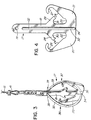
- boom 14 (FIGURE 2) having a sheave 15 at the free end thereof. From the sheave 15 extends a suspension cable 16 the lower end of which is secured to a hook 17 which will now be described in greater detail.
- the hook 17 is made of steel and includes a flat stem 18. At a normally upper end of the stem 18, a lifting eye 19 is provided. The lower end of the stem 18 merges with two opposed hook portions 20, 21.
- the hook portions 20, 21 and the stem 18 are coincident with a plane which, for convenience, will be referred to as "a first reference plane". Such reference plane is generally parallel in the plane of the views of FIGURE 4.
- Each hook portion 20, 21 includes a concavely curved load supporting section 22, 23, respectively, which presents an upwardly open cavity at the merger of the hook portion 20, 21 with the stem 18.
- the hook portion 20, 21 then continues, by way of an upwardly and outwardly inclined side section 24, 25.
- the upward end of each side section 24, 25 terminates by way of an inwardly and downwardly turned tip section 26, 27.
- Each nose portion 28, 29 protrudes, in coplanar relationship with the first reference plane, away from the stem 18 and slightly downwardly to define a downwardly open, concavely curved engagement surface 30, 31 disposed just above the respective load supporting section 22, 23.
- the concavely shaped load supporting sections 22, 23, the inwardly and downwardly curved tip sections 26 and 27 and the engagement surfaces 30, 31 are all of a semi-circular configuration the radius of which generally corresponds or is very slightly greater than the radius of the outer surface of the rigid eye 11. It will be appreciated that the three concave elements of each hook portion 20, 21 as described cooperate in preventing inadvertent disengagement of the rod of the eye 11 from the hook 17 which might otherwise be caused by rough seas or the like.
- the hook 17 is provided with a pair of hook rolling members 32, 33, one protruding from each face of the stem 18.
- the hook rolling members 32, 33 are arcuately shaped, providing each with an outer surface coinciding, at 34 or 35 with the stem 18.
- the outer surface of the members 32, 33 then extends away from the said first reference plane until it reaches the maximum distance therefrom at 36 or 37, to again gradually return back to the first reference plane at joinders 38, 39. It is apparent from the drawings that the hook rolling members both coincide with a second reference plane which is perpendicular to the first reference plane.
- FIGURES 1 and 2 show a tag line 40 secured to an eye 41 (FIGURE 3) at the lower end of the suspension cable 16.
- the line 40 is not shown in FIGURE 3.
- the other end of the first tag line 40 is manipulated by a crew member on the rescue ship or rig to control the swinging of the hook 17, thus facilitating the manipulation of the hook into engagement with the eye 11 centrally above the boat 10.
- the crane mechanism can be actuated to lift the boat 10.
- the boat When the boat is being lifted, it may become necessary to prevent its pivoting about a vertical axis generally coincident with the peak portion of the eye 11. This can be prevented by utilizing a device for securing a tag line to the boat, which will now be described.
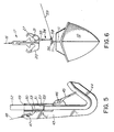
- the device for securing the tag line to the boat is indicated by reference numeral 42. It is shown in greater detail in FIGURE 5.
- the device comprises a snap-on hook arrangement including a hook body 43 the front end of which is integral with a hook section 44.
- the inside surface of the hook section 44 is engaged by a free end portion of a locking member 45 which is disposed at an angle relative to the hook section 44 and is pivotal at 46.
- the locking member 45 is urged by a spring (not shown) into engagement with the hook section 44.
- the locking member 45 is first urged to pivot clockwise when viewed in FIGURE 5, to thus open and allow the passage of the eye 12 or 13 inside the hook section 44, whereupon the locking member 45 snaps back anticlockwise arresting the elongate member of the eye 12 or 13 inside the hook.
- the arrangement of the snap-on hook is very well known in different fields of technology and does not have to be described in greater detail.
- the body 43 of the snap-on hook also comprises an eye 47 to which is secured one end of what is referred to as a second tag line 48.
- a socket 49 is provided in which is fixedly secured a centrally and transversely arranged pin 50, approximately two inches from the opening of the socket 49.
- the socket is of a cylindric configuration complementary with the cylindric end portion 51 of an extension rod or handle 52.
- the end portion 51 of the extension rod 52 is provided with a slot 53 at its forward end such that the pin 50 may be received within the slot 53.
- the extension rod 52 is of a tubular configuration and that, therefore, the slot 53 is provided in opposed wall sections of the tube.
- the slot engaging the pin 52 effectively prevents relative pivotal movement about the axis of the socket 49 between the body 43 and the extension rod 52.
- the second tag line 48 if held tight at the remote end of the rod 52, effectively prevents inadvertent withdrawal of the extension rod 52 from the socket 49, to the left of FIGURE 5.
- the extension rod is approximately 20 feet long which is sufficient for securing to the eyes 12, 13 of a suspended lifeboat the respective second tag line 48.
- one of the second tag lines 48 is shown already secured to the fore eye 12, the rod 52 having been removed, while the snap-on hook of the tag line 48 at the left of FIGURE 2 is being manipulated, by rod 52, into engagement with the eye 13 at the aft end of the lifeboat 10.
- both tag lines 48 are secured to the respective eyes 12, 13, the boat can be very easily manipulated from the ship into the appropriate position.
- the described elements of the lifeboat lifting device allow the engagement of appropriate elements with a lifeboat, when retrieving same, without the need of any person to be at the lifeboat to engage the hook of the lifting crane with the appropriate lifting eye of the boat, as is required in the known systems.
- a secondary hook 54 is provided, the upper end of which has a suspension eye 55 the size and configuration of which is such that the eye 55 can be loosely hooked onto the hook portion 20 or 21 of the hook 17.
- the hook 54 has only a single hook section 56 which is relatively smooth and is devoid of any protrusions such as have been described in connection with the hook 17.
- an eye 58 is provided to which is tied a third tag line 59.
- second tag lines 48 can be utilized to steady the boat along the launching vessel as long as the secondary hook 54 is engaged with the eye 11 such that its hook section 56 faces away from the vessel.
- the third tag line 59 is maintained under a slight tension. As soon as the boat reaches the surface of water and the hook section 56 becomes loose on the eye 11, a continued pull on the third tag line 59 will bring the hook 54 out of engagement with the eye 11.
- a continued pull on the third tag line 59 cannot result in inadvertent removal of the secondary hook 54 from the hook 17 due to the inwardly and downwardly turned tip section 27.
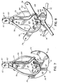
- FIGURES 7, 8 and 9 A modified version of the hook described above is shown in FIGURES 7, 8 and 9. It will now be described in detail.
- FIGURE 8 shows a first mode, also referred to as "self-releaseable mode".
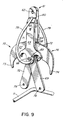
- FIGURE 9 shows the crane hook in a released position, acquired after a boat or the like has become lowered to the water level and
- FIGURE 7 shows the hook in a rigid position, in which the hook is virtually equivalent in function to the hook of FIGURE 3.
- the hook comprises three basic elements which are pivotably secured to each other, namely a yoke 60 the upper end 61 of which is provided with a suspension eye 62 or a like arrangement enabling the suspension of the entire assembly from a crane cable or the like.
- the yoke 60 has an elongated front plate 63 and an identical rear plate 64 the two plates being connected to each other near the upper end 61 to form a general arrangement of an inverted U. Near the upper end 61 are provided coaxial locking pin openings 65, FIGURE 8. The opening 65 of the rear plate 64 is not visible in the drawings.
- each J-shaped member is comprised of a stem portion 69, 70; a base portion 71, 72 and a hook portion 73, 74 which forms a continuation or extension of the respective base portion 71, 72.
- the J-shaped member whose stem portion 69 extends to the right of FIGURE 8 is designated with reference number 75, while that whose stem portion 70 extends to the left-hand side of FIGURE 8 is designated with reference number 76.
- numeral 77 designates a security pin received in the pin openings 65 and passing also through passages 78, 79 at the free ends of the stem portions 69, 70.
- the passages 78, 79 of course are also coaxial with the pin 77 and with openings 65, when the hook is in the rigid state of FIGURE 7.
- the security pin 77 thus keeps the arms 69, 70 of the J-shaped members in a generally vertical position as shown in FIGURE 7.
- the hook is ready for retrieval and is practically of the same arrangement as the hook of FIGURE 3.
- the arched tubes 78, 79 welded to the plates 63, 64 have exactly the same purpose and operation as the rolling members 32, 33 referred to above.
- the pin 77 is removed from the openings 65, 78, 79, and the arms 69, 70 are manipulated into the position of FIGURE 8 on a ship, a helicopter, a drilling rig platform or the like so as to make the hook portions 73, 74 surround a rigid tube of the eye 11 mounted on a lifeboat or the like as shown, e.g. in FIGURE 8.
- the arms 69, 70 are being manipulated by pivoting about pivot 63. Once the two J-shapes members 75, 76 are placed into engagement with the tube 11 the crane associated with the hook is actuated to raise the hook to remove any slack from the hook suspending cable 16 and to tension the cable.
- a supplemental safety pin 82 (FIGURE 8) inserted in an opening 83, FIGURE 7, can be used to prevent inadvertent, accidental release. If we now assume that the crane raises the hook and with it the boat which is fixed to the tube 11, one can see that the boat is now ready to be launched. When the boat is manipulated to the side of the drilling rig platform or a ship, it is lowered. The supplemental pin 82 is removed as soon as there is no danger of the free ends of arms hitting an object. With the pin 82 removed, the boat is now lowered to the sea.
- the J-shaped members 69, 70 are manually pivoted such as to become generally coincident with the yoke as shown in FIGURE 7.
- the locking pin 77 is reinserted in aligned openings 65, 78, 79 to reach the state described above.
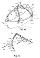
- the present invention also provides an improved water craft lifting frame and reference is now made to FIGURES 10, 11, 12 and 13 of the drawings.
- a lifting frame comprises a triangulated, tubular assembly 98 which is secured, for and aft, to the lifeboat 90 above the water-line thereof.
- Assembly 98 comprises a pair of spaced Y-socket joints 100, 102 interconnected by an apex tubular member 104.
- Each Y-socket joint, 100, 102 has a pair of legs 106 which receive the upper ends of assembly tubular members connected, at their other ends, to the forward and aft ends of the water craft.
- tubular members 108, 110 connect the apex 104 to the starboard and port side respectively of the forward end of the lifeboat 90 while members 112 and 114 connect to the starboard and port sides respectively of the aft end of the lifeboat 90.
- gusset plates 124 can be provided in the structure in the area of the Y-socket joints 100 and 102, as illustrated in Figure 11.
- tubular members of assembly 98 enclose a pair of cables, 126 and 128 which are also anchored to the lifeboat 90 above the water-line thereof, in combination with the lower ends of the tubular members 108-114. Moreover, each cable runs diagonally from its anchorage at one end of the water craft to the other. Thus, and shown in Figure 11, cable 126 is enclosed at ⁇ the forward end of the craft 90 in tubular member 108 and is anchored therein to the forward, starboard side of the water craft.
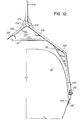
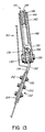
- FIG. 12 The apparatus anchoring the assembly 98 to the craft 90 is shown in Figures 12 and 13.
- the lower end of that member 110 is engaged with a swage socket 130 which in turn is engaged with a connection plate 132 secured to the craft 90 at the gunwale area 134 thereof.
- the lower end of the suspension cable (in this case, cable 128) is secured in the upper end of the swage socket 130, the lower end of the socket having a pair of open, parallel plates 136 which, together with the upper end of the anchor plate 132, are drilled to receive an anchor pin 138 which serves to secure the swage socket 130 and the anchor plate 132 together.
- rigid or resilient spacers 140 can be utilized between the cheeks of the upper end of the anchor plate 132 and the inside services of the legs 136 of the swage socket.
- tubular member 110 is threaded as at 142 to receive an adjustment nut 144 and lock nut 146 which secures the lower end of tubular member 110 to the swage socket sleeve 148.
- anchor plate 132 is shown secured to the gunwale area of the craft 90 by a plurality of suitable fastening means such as bolts 150, the heads 152 thereof being preferably welded to reinforcing plate 154 located on the inside of the wall of the craft.
Landscapes
- Engineering & Computer Science (AREA)
- Mechanical Engineering (AREA)
- Chemical & Material Sciences (AREA)
- Combustion & Propulsion (AREA)
- Ocean & Marine Engineering (AREA)
- Load-Engaging Elements For Cranes (AREA)
- Non-Silver Salt Photosensitive Materials And Non-Silver Salt Photography (AREA)
- Devices For Checking Fares Or Tickets At Control Points (AREA)
Applications Claiming Priority (4)
| Application Number | Priority Date | Filing Date | Title |
|---|---|---|---|
| CA495842 | 1985-11-21 | ||
| CA495842 | 1985-11-21 | ||
| US930563 | 1986-11-14 | ||
| US06/930,563 US4763943A (en) | 1985-11-21 | 1986-11-14 | Crane hook |
Publications (2)
| Publication Number | Publication Date |
|---|---|
| EP0223231A2 true EP0223231A2 (de) | 1987-05-27 |
| EP0223231A3 EP0223231A3 (de) | 1988-02-17 |
Family
ID=25670845
Family Applications (1)
| Application Number | Title | Priority Date | Filing Date |
|---|---|---|---|
| EP86115981A Withdrawn EP0223231A3 (de) | 1985-11-21 | 1986-11-19 | Vorrichtung zum Heben und Senken von Booten oder dergleichen |
Country Status (3)
| Country | Link |
|---|---|
| EP (1) | EP0223231A3 (de) |
| FI (1) | FI864741A7 (de) |
| NO (1) | NO864607L (de) |
Cited By (2)
| Publication number | Priority date | Publication date | Assignee | Title |
|---|---|---|---|---|
| DE102006032299B3 (de) * | 2006-07-11 | 2007-12-06 | Bundesrepublik Deutschland, vertreten durch das Bundesministerium der Verteidigung, dieses vertreten durch den Präsidenten des Bundesamtes für Wehrtechnik und Beschaffung | Koppelsystem für eine Heißvorrichtung für Boote |
| EP1670674A4 (de) * | 2003-07-03 | 2011-07-20 | Advanced Maritime Support Technology Inc | Schiffsnutzlasthandhabungsfahrzeug und -system |
Family Cites Families (10)
| Publication number | Priority date | Publication date | Assignee | Title |
|---|---|---|---|---|
| DE78930C (de) * | J. G. Schneider, Oelsnitz i. V | Greifklaue für Hebezeuge | ||
| CA545476A (en) * | 1957-08-27 | D. Mills Christopher | Boat raising, lowering, engaging and disengaging gear | |
| US221697A (en) * | 1879-11-18 | Improvement in attachments for pulley-blocks | ||
| US184701A (en) * | 1876-11-28 | Improvement in self-detaching hooks for boats | ||
| US891598A (en) * | 1907-08-05 | 1908-06-23 | Kieran John Daly | Boat-releasing device. |
| US2370312A (en) * | 1944-07-17 | 1945-02-27 | Herman Jack | Self-releasing hoisting hook |
| US3055697A (en) * | 1960-07-01 | 1962-09-25 | United States Steel Corp | Lift hook with self-operating safety latch |
| GB1051482A (de) * | 1963-03-11 | 1900-01-01 | ||
| US3343189A (en) * | 1965-08-24 | 1967-09-26 | Richard A Pollard | Rescue litter floatation assembly |
| DE2322762A1 (de) * | 1973-05-05 | 1974-11-21 | Theodor Haering | Krangeschirr |
-
1986
- 1986-11-19 EP EP86115981A patent/EP0223231A3/de not_active Withdrawn
- 1986-11-19 NO NO864607A patent/NO864607L/no unknown
- 1986-11-20 FI FI864741A patent/FI864741A7/fi not_active IP Right Cessation
Cited By (2)
| Publication number | Priority date | Publication date | Assignee | Title |
|---|---|---|---|---|
| EP1670674A4 (de) * | 2003-07-03 | 2011-07-20 | Advanced Maritime Support Technology Inc | Schiffsnutzlasthandhabungsfahrzeug und -system |
| DE102006032299B3 (de) * | 2006-07-11 | 2007-12-06 | Bundesrepublik Deutschland, vertreten durch das Bundesministerium der Verteidigung, dieses vertreten durch den Präsidenten des Bundesamtes für Wehrtechnik und Beschaffung | Koppelsystem für eine Heißvorrichtung für Boote |
Also Published As
| Publication number | Publication date |
|---|---|
| FI864741A0 (fi) | 1986-11-20 |
| NO864607D0 (no) | 1986-11-19 |
| FI864741A7 (fi) | 1987-05-22 |
| NO864607L (no) | 1987-05-22 |
| EP0223231A3 (de) | 1988-02-17 |
Similar Documents
| Publication | Publication Date | Title |
|---|---|---|
| US4083072A (en) | Connection system for marine structures | |
| US3993011A (en) | Method and apparatus for retrieving, securing, and launching an anchor buoy | |
| US6457908B1 (en) | Method and apparatus for suction anchor and mooring deployment and connection | |
| US6122847A (en) | Method of and apparatus for installation of plate anchors | |
| EP3365224B1 (de) | System und verfahren zum ablegen und zurückholen eines schiffs | |
| US5378851A (en) | System for handling a remotely operated vessel | |
| US4763943A (en) | Crane hook | |
| EP3188960B1 (de) | Schiffswiedererlangungssystem und -verfahren | |
| US6685396B1 (en) | Method and apparatus for suction anchor and mooring deployment and connection | |
| JP5444335B2 (ja) | 連結具 | |
| NO136725B (de) | ||
| JP2019518664A (ja) | 緊急船舶抑留システムおよび方法 | |
| US4655158A (en) | Boat anchor including releasable coupling means | |
| KR101632682B1 (ko) | 커플링 | |
| KR101759195B1 (ko) | 무인선 회수용 결합장치 및 이를 이용한 결합 제어방법 | |
| AU743420B2 (en) | Method and apparatus for suction anchor and mooring deployment and connection | |
| EP0223231A2 (de) | Vorrichtung zum Heben und Senken von Booten oder dergleichen | |
| EP0929438B1 (de) | Seenotrettungsgerät | |
| US4417538A (en) | Marine anchor with release capability | |
| US5529010A (en) | Transom link method and apparatus | |
| US4246860A (en) | Method for anchor retrieval | |
| GB1578129A (en) | Anchor retrieval devices | |
| GB2279619A (en) | Method of and apparatus for capturing floating objects | |
| EP1777152B1 (de) | Rückziehbare ferngesteuerte Schnellentrigelungsverankerungsvorrichtung | |
| EP0414321A1 (de) | Kippdavit für Freifall-Rettungsboote |
Legal Events
| Date | Code | Title | Description |
|---|---|---|---|
| PUAI | Public reference made under article 153(3) epc to a published international application that has entered the european phase |
Free format text: ORIGINAL CODE: 0009012 |
|
| AK | Designated contracting states |
Kind code of ref document: A2 Designated state(s): DE FR GB SE |
|
| RAP1 | Party data changed (applicant data changed or rights of an application transferred) |
Owner name: MM & M CONSULTANTS LIMITED |
|
| PUAL | Search report despatched |
Free format text: ORIGINAL CODE: 0009013 |
|
| AK | Designated contracting states |
Kind code of ref document: A3 Designated state(s): DE FR GB SE |
|
| 17P | Request for examination filed |
Effective date: 19880818 |
|
| 17Q | First examination report despatched |
Effective date: 19890613 |
|
| STAA | Information on the status of an ep patent application or granted ep patent |
Free format text: STATUS: THE APPLICATION IS DEEMED TO BE WITHDRAWN |
|
| 18D | Application deemed to be withdrawn |
Effective date: 19901017 |