EP0223314A2 - Dispositif et méthode de mise en place de panneaux de construction - Google Patents
Dispositif et méthode de mise en place de panneaux de construction Download PDFInfo
- Publication number
- EP0223314A2 EP0223314A2 EP86202046A EP86202046A EP0223314A2 EP 0223314 A2 EP0223314 A2 EP 0223314A2 EP 86202046 A EP86202046 A EP 86202046A EP 86202046 A EP86202046 A EP 86202046A EP 0223314 A2 EP0223314 A2 EP 0223314A2
- Authority
- EP
- European Patent Office
- Prior art keywords
- supporting table
- frame
- sub
- building
- pivot
- Prior art date
- Legal status (The legal status is an assumption and is not a legal conclusion. Google has not performed a legal analysis and makes no representation as to the accuracy of the status listed.)
- Granted
Links
Images


Classifications
-
- E—FIXED CONSTRUCTIONS
- E04—BUILDING
- E04G—SCAFFOLDING; FORMS; SHUTTERING; BUILDING IMPLEMENTS OR AIDS, OR THEIR USE; HANDLING BUILDING MATERIALS ON THE SITE; REPAIRING, BREAKING-UP OR OTHER WORK ON EXISTING BUILDINGS
- E04G21/00—Preparing, conveying, or working-up building materials or building elements in situ; Other devices or measures for constructional work
- E04G21/14—Conveying or assembling building elements
- E04G21/16—Tools or apparatus
-
- B—PERFORMING OPERATIONS; TRANSPORTING
- B62—LAND VEHICLES FOR TRAVELLING OTHERWISE THAN ON RAILS
- B62B—HAND-PROPELLED VEHICLES, e.g. HAND CARTS OR PERAMBULATORS; SLEDGES
- B62B1/00—Hand carts having only one axis carrying one or more transport wheels; Equipment therefor
- B62B1/26—Hand carts having only one axis carrying one or more transport wheels; Equipment therefor characterised by supports specially adapted to objects of definite shape
-
- B—PERFORMING OPERATIONS; TRANSPORTING
- B62—LAND VEHICLES FOR TRAVELLING OTHERWISE THAN ON RAILS
- B62B—HAND-PROPELLED VEHICLES, e.g. HAND CARTS OR PERAMBULATORS; SLEDGES
- B62B1/00—Hand carts having only one axis carrying one or more transport wheels; Equipment therefor
- B62B1/26—Hand carts having only one axis carrying one or more transport wheels; Equipment therefor characterised by supports specially adapted to objects of definite shape
- B62B1/268—Hand carts having only one axis carrying one or more transport wheels; Equipment therefor characterised by supports specially adapted to objects of definite shape the objects being plates, doors, panels or the like
-
- E—FIXED CONSTRUCTIONS
- E04—BUILDING
- E04G—SCAFFOLDING; FORMS; SHUTTERING; BUILDING IMPLEMENTS OR AIDS, OR THEIR USE; HANDLING BUILDING MATERIALS ON THE SITE; REPAIRING, BREAKING-UP OR OTHER WORK ON EXISTING BUILDINGS
- E04G21/00—Preparing, conveying, or working-up building materials or building elements in situ; Other devices or measures for constructional work
- E04G21/14—Conveying or assembling building elements
- E04G21/16—Tools or apparatus
- E04G21/167—Tools or apparatus specially adapted for working-up plates, panels or slab shaped building elements
-
- E—FIXED CONSTRUCTIONS
- E04—BUILDING
- E04G—SCAFFOLDING; FORMS; SHUTTERING; BUILDING IMPLEMENTS OR AIDS, OR THEIR USE; HANDLING BUILDING MATERIALS ON THE SITE; REPAIRING, BREAKING-UP OR OTHER WORK ON EXISTING BUILDINGS
- E04G21/00—Preparing, conveying, or working-up building materials or building elements in situ; Other devices or measures for constructional work
- E04G21/14—Conveying or assembling building elements
- E04G21/16—Tools or apparatus
- E04G21/167—Tools or apparatus specially adapted for working-up plates, panels or slab shaped building elements
- E04G21/168—Tools or apparatus specially adapted for working-up plates, panels or slab shaped building elements used for tilting, e.g. from horizontal to vertical position or vice versa
-
- B—PERFORMING OPERATIONS; TRANSPORTING
- B62—LAND VEHICLES FOR TRAVELLING OTHERWISE THAN ON RAILS
- B62B—HAND-PROPELLED VEHICLES, e.g. HAND CARTS OR PERAMBULATORS; SLEDGES
- B62B2203/00—Grasping, holding, supporting the objects
- B62B2203/05—Rocking means for facilitating tilting of the cart, e.g. by loading
Definitions
- the invention relates to a method for arranging building panels, as designated in the heading of claim 8.
- the invention has for its object to make this work easier to perform.
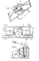
- the device 1 according to the invention that is shown in fig. 2 is assembled from a sub-frame 2 and a supporting table 3 which are disconnectably attached tog-ether by means of a pivot rod 4.
- the sub-frame 2 consists of a nonrotating shaft 5 which has at both ends a freely rotatable wheel 6 mounted with bearings and having a pneumatic tyre 7. Close to the one wheel 6 there is welded on the shaft 5 and directed at right angles to it a pivot bar 8 which,has two pivot ears 19, one on either side of the shaft 5. Close to the other wheel 6 a support 10 is present to which is fastened the end of a chain 11.
- the supporting table 3 is built up of two longitudinal girders 13 and 18 having three transversely directed corner profiles 14 to the top side of which are attached protruding wooden beams 15 on which a building panel 9 can rest while running little risk of being damaged.
- a rectangular small frame 16 having longitudinal girders 27 and 28 is rigidly connected to longitudinal girders 13 and corner profiles 14 with supports 17 directed inclining upwards.
- the frame 16 has pivot holes 20, with the result that the pivot rod 4 provided with a handle can be placed through these pivot holes 20 and ears 19, whereby the parts 2 and 3, which are in themselves light and can be carried separately from each other by hand, can be easily combined into a device 1 according to the invention.
- the free end of chain 11 is hooked onto a hook 24 which is attached to the longitudinal girder 28, which can be seen in the drawing.
- the longitudinal girder 27 has an upright, U-shaped gripper member 30 welded to it.
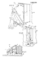
- building panels 9 as a series 33 of building panels 9 which are positioned against each other with their long side 34 on two wooden supports 35 located at a good distance from each other (fig. 6), are placed in a building frame 36. These building panels 9 have then to be arranged on end (see fig. 10).
- the method according to the invention can be carried out easily and quickly by one person using the device 1.
- the supporting table 3 is first tilted relative to sub-frame 2 from the position in fig. 2 into the slightly inclining, downward position of fig. 3.
- the chain 11 determines the maximum tilt position.
- Teeth 37 attached to the lower longitudinal girder 13 thereby protrude sideways outside the supporting surface 38.
- the teeth 37 are situated symmetrically on either side of shaft 5 at a substantial interval a from each other.
- the teeth 37 are located at a low level beneath the long side 34 of the foremost building panel 9 when the device 1, being manoeuvred at a slight slant, is moved against this building panel 9.
- the building panel 9 is then pulled a little towards the device 1 at this point with the hook 40 as according to arrow 41 with the result that it comes parallel to the lower edge of supporting table 3.
- a separate lever 42 for example steel pipe, is then inserted into the gripper member 30, the hook 40 is hooked around a support 17 close to the upper longitudinal girder 13 and the supporting table 3 is tipped over together with the building panel 9 as according to arrow 44 on pivot rod 4 by means of lever 42.
- pivot rod 4 By making a good choice of the arrangement of pivot rod 4, that is, at a height of for example 30 to 40 cm from the ground, little force is necessary when tipping over. The last part of the tipping movement is slightly decelerated with the same lever 42.
- the hook 40 can if necessary be first pulled slightly to help start the tipping movement and if required the movement is cushioned somewhat at the end with the hook.
- the lever 42 is removed (see fig. 7).
- a piece of the building panel 9 is then if necessary sawn off, whereby an end 46 is then laid on a table 47.
- the device 1 then also serves as sawing table.
- the building panel 9 is then moved with device 1 to the set-up location 48, whereby the lower side 49 of building panel 9 is set down near the set-up location 48, whereby the supporting table is tilted on the shaft 5.
- the building panel 9 is then lifted from the device 1, whereby building panel 9 is tilted on its lower edge 49 so as to be pointed upright as according to arrow 50.
- the person 51 hereby walks around the device, whereby the building panel 9 is also turned on the corner 52 in arrow direction 53, so that the corner 54 comes approximately up against the already arranged adjacent building panel 9.
- the building panel 9 to be handled is if necessary moved a little with swivel steps, which is not a heavy operation.
- the device 61 of fig. 11 corresponds with device 1, with the understanding that the sub-frame 62 of the former has a bush 63 which can slide on the shaft 5, to which bush the pivot bar 8 is welded.
- the downward tilted supporting table 3 can be placed against the foremost building panel 9 somewhat more easily, so that the first operation of placing the supporting table 3 parallel to the building panel 9 is superfluous.
- the sub-frame 2 instead of having one wheel axle with two wheels, can thus have for example three or four wheels, at least one of which is a swivelling wheel.
- the third and possibly the fourth wheel can be raised during tilting on the fulcra of the other two wheels.
- one of the both ends of supporting table 3 has a fixed support which functions as the legs of a wheelbarrow for setting down the supporting table during sawing without a table 47 being necessary.
Landscapes
- Engineering & Computer Science (AREA)
- Architecture (AREA)
- Mechanical Engineering (AREA)
- Civil Engineering (AREA)
- Structural Engineering (AREA)
- Chemical & Material Sciences (AREA)
- Combustion & Propulsion (AREA)
- Transportation (AREA)
- Workshop Equipment, Work Benches, Supports, Or Storage Means (AREA)
- Handcart (AREA)
Applications Claiming Priority (2)
| Application Number | Priority Date | Filing Date | Title |
|---|---|---|---|
| NL8503229 | 1985-11-22 | ||
| NL8503229A NL8503229A (nl) | 1985-11-22 | 1985-11-22 | Werktuig en werkwijze voor het opstellen van bouwplaten. |
Publications (3)
| Publication Number | Publication Date |
|---|---|
| EP0223314A2 true EP0223314A2 (fr) | 1987-05-27 |
| EP0223314A3 EP0223314A3 (en) | 1988-10-12 |
| EP0223314B1 EP0223314B1 (fr) | 1991-05-02 |
Family
ID=19846907
Family Applications (1)
| Application Number | Title | Priority Date | Filing Date |
|---|---|---|---|
| EP86202046A Expired - Lifetime EP0223314B1 (fr) | 1985-11-22 | 1986-11-19 | Dispositif et méthode de mise en place de panneaux de construction |
Country Status (3)
| Country | Link |
|---|---|
| EP (1) | EP0223314B1 (fr) |
| DE (1) | DE3679033D1 (fr) |
| NL (1) | NL8503229A (fr) |
Cited By (8)
| Publication number | Priority date | Publication date | Assignee | Title |
|---|---|---|---|---|
| EP0413381A1 (fr) * | 1989-08-18 | 1991-02-20 | Durox Nederland B.V. | Procédé et dispositif pour le montage de panneaux |
| EP0779198A1 (fr) * | 1995-12-14 | 1997-06-18 | Ytong Nederland B.V. | Méthode et dispositif pour le transport d'objets |
| EP0960992A3 (fr) * | 1998-05-29 | 2000-01-26 | Franz Carl Nüdling Basaltwerke GmbH & Co. KG | Appareils et méthode pour la manutention d'éléments en forme de plaque |
| CN105544995A (zh) * | 2016-01-30 | 2016-05-04 | 山东天意机械股份有限公司 | 墙板安装车 |
| AU2014204487B2 (en) * | 2013-07-18 | 2017-11-16 | Csr Building Products Limited | Mobile support device |
| CN110406571A (zh) * | 2019-07-01 | 2019-11-05 | 中国十七冶集团有限公司 | 一种自制简易预制板运输小推车 |
| CN112324026A (zh) * | 2020-11-13 | 2021-02-05 | 湖南省方为节能建材有限责任公司 | 一种建筑幕墙加工用辅助装置 |
| GB2592399A (en) * | 2020-02-27 | 2021-09-01 | Moulded Foams Ltd | Apparatus for beam moving |
Family Cites Families (4)
| Publication number | Priority date | Publication date | Assignee | Title |
|---|---|---|---|---|
| US3335883A (en) * | 1965-10-11 | 1967-08-15 | Perryville Mfg Company | Lift truck |
| US3540753A (en) * | 1969-01-27 | 1970-11-17 | Derrick S Hanson | Hand truck |
| SE406443B (sv) * | 1977-08-12 | 1979-02-12 | Kilenstam Bjorn | Transportvagn |
| DE3434367A1 (de) * | 1983-09-28 | 1985-05-09 | Karl Wien Glockenstein | Anlage zum transport und aufstellen von bauteilen |
-
1985
- 1985-11-22 NL NL8503229A patent/NL8503229A/nl not_active Application Discontinuation
-
1986
- 1986-11-19 DE DE8686202046T patent/DE3679033D1/de not_active Expired - Fee Related
- 1986-11-19 EP EP86202046A patent/EP0223314B1/fr not_active Expired - Lifetime
Cited By (10)
| Publication number | Priority date | Publication date | Assignee | Title |
|---|---|---|---|---|
| EP0413381A1 (fr) * | 1989-08-18 | 1991-02-20 | Durox Nederland B.V. | Procédé et dispositif pour le montage de panneaux |
| EP0779198A1 (fr) * | 1995-12-14 | 1997-06-18 | Ytong Nederland B.V. | Méthode et dispositif pour le transport d'objets |
| EP0960992A3 (fr) * | 1998-05-29 | 2000-01-26 | Franz Carl Nüdling Basaltwerke GmbH & Co. KG | Appareils et méthode pour la manutention d'éléments en forme de plaque |
| AU2014204487B2 (en) * | 2013-07-18 | 2017-11-16 | Csr Building Products Limited | Mobile support device |
| CN105544995A (zh) * | 2016-01-30 | 2016-05-04 | 山东天意机械股份有限公司 | 墙板安装车 |
| CN105544995B (zh) * | 2016-01-30 | 2017-06-30 | 山东天意机械股份有限公司 | 墙板安装车 |
| CN110406571A (zh) * | 2019-07-01 | 2019-11-05 | 中国十七冶集团有限公司 | 一种自制简易预制板运输小推车 |
| GB2592399A (en) * | 2020-02-27 | 2021-09-01 | Moulded Foams Ltd | Apparatus for beam moving |
| CN112324026A (zh) * | 2020-11-13 | 2021-02-05 | 湖南省方为节能建材有限责任公司 | 一种建筑幕墙加工用辅助装置 |
| CN112324026B (zh) * | 2020-11-13 | 2022-07-29 | 湖南省方为节能建材有限责任公司 | 一种建筑幕墙加工用辅助装置 |
Also Published As
| Publication number | Publication date |
|---|---|
| EP0223314B1 (fr) | 1991-05-02 |
| EP0223314A3 (en) | 1988-10-12 |
| DE3679033D1 (de) | 1991-06-06 |
| NL8503229A (nl) | 1987-06-16 |
Similar Documents
| Publication | Publication Date | Title |
|---|---|---|
| US4793624A (en) | Small, lightweight, strong, multiple use cart having a removable vertical support for moving heavy items in or out of dwellings via a person size doorway | |
| US4488733A (en) | Wheeled plate carrier | |
| JP2625323B2 (ja) | ビーム部材 | |
| US4978132A (en) | Pivotable hand truck apparatus | |
| US2815132A (en) | Machine for hoisting and positioning building board | |
| US4262773A (en) | Portable scaffold | |
| US6511275B2 (en) | Drywall panel carrier attachable to lift platform | |
| US5427356A (en) | Lift and portable lift | |
| US3930548A (en) | Motorized scaffold attachment | |
| US4230329A (en) | Mobile cart | |
| US6250655B1 (en) | Leveraging transport system for tables plasterboard sheets and the like | |
| US3931751A (en) | Collapsible mounting for power saw units | |
| KR101987369B1 (ko) | 사다리, 작업대 겸용 상하차 운반기구 | |
| EP0223314A2 (fr) | Dispositif et méthode de mise en place de panneaux de construction | |
| US4274507A (en) | Portable support for a scaffold | |
| US4815395A (en) | Tilt-top table | |
| US4641822A (en) | Wood holder | |
| US5022670A (en) | Separable creeper having a non-planar support surface | |
| US4845974A (en) | Vehicle chassis straightening bench | |
| US4117939A (en) | Moveable building board hoist | |
| US3851728A (en) | Scaffold | |
| AU2014204487B2 (en) | Mobile support device | |
| EP0413381B1 (fr) | Procédé et dispositif pour le montage de panneaux | |
| US3417877A (en) | Portable hoist | |
| JP3087217B2 (ja) | パネル材収納部付き高所作業車 |
Legal Events
| Date | Code | Title | Description |
|---|---|---|---|
| PUAI | Public reference made under article 153(3) epc to a published international application that has entered the european phase |
Free format text: ORIGINAL CODE: 0009012 |
|
| AK | Designated contracting states |
Kind code of ref document: A2 Designated state(s): BE DE FR GB LU NL |
|
| PUAL | Search report despatched |
Free format text: ORIGINAL CODE: 0009013 |
|
| AK | Designated contracting states |
Kind code of ref document: A3 Designated state(s): BE DE FR GB LU NL |
|
| 17P | Request for examination filed |
Effective date: 19880915 |
|
| 17Q | First examination report despatched |
Effective date: 19891005 |
|
| GRAA | (expected) grant |
Free format text: ORIGINAL CODE: 0009210 |
|
| AK | Designated contracting states |
Kind code of ref document: B1 Designated state(s): BE DE FR GB LU NL |
|
| REF | Corresponds to: |
Ref document number: 3679033 Country of ref document: DE Date of ref document: 19910606 |
|
| ET | Fr: translation filed | ||
| PLBE | No opposition filed within time limit |
Free format text: ORIGINAL CODE: 0009261 |
|
| STAA | Information on the status of an ep patent application or granted ep patent |
Free format text: STATUS: NO OPPOSITION FILED WITHIN TIME LIMIT |
|
| 26N | No opposition filed | ||
| PGFP | Annual fee paid to national office [announced via postgrant information from national office to epo] |
Ref country code: GB Payment date: 19921102 Year of fee payment: 7 |
|
| PGFP | Annual fee paid to national office [announced via postgrant information from national office to epo] |
Ref country code: BE Payment date: 19921104 Year of fee payment: 7 |
|
| PGFP | Annual fee paid to national office [announced via postgrant information from national office to epo] |
Ref country code: FR Payment date: 19921123 Year of fee payment: 7 |
|
| PGFP | Annual fee paid to national office [announced via postgrant information from national office to epo] |
Ref country code: NL Payment date: 19921130 Year of fee payment: 7 Ref country code: DE Payment date: 19921130 Year of fee payment: 7 |
|
| PGFP | Annual fee paid to national office [announced via postgrant information from national office to epo] |
Ref country code: LU Payment date: 19921216 Year of fee payment: 7 |
|
| EPTA | Lu: last paid annual fee | ||
| PG25 | Lapsed in a contracting state [announced via postgrant information from national office to epo] |
Ref country code: LU Free format text: LAPSE BECAUSE OF NON-PAYMENT OF DUE FEES Effective date: 19931119 Ref country code: GB Effective date: 19931119 |
|
| PG25 | Lapsed in a contracting state [announced via postgrant information from national office to epo] |
Ref country code: BE Effective date: 19931130 |
|
| BERE | Be: lapsed |
Owner name: DUROX GASBETON B.V. Effective date: 19931130 |
|
| PG25 | Lapsed in a contracting state [announced via postgrant information from national office to epo] |
Ref country code: NL Effective date: 19940601 |
|
| GBPC | Gb: european patent ceased through non-payment of renewal fee |
Effective date: 19931119 |
|
| NLV4 | Nl: lapsed or anulled due to non-payment of the annual fee | ||
| PG25 | Lapsed in a contracting state [announced via postgrant information from national office to epo] |
Ref country code: FR Effective date: 19940729 |
|
| PG25 | Lapsed in a contracting state [announced via postgrant information from national office to epo] |
Ref country code: DE Effective date: 19940802 |
|
| REG | Reference to a national code |
Ref country code: FR Ref legal event code: ST |