EP0223329B1 - Valve pour ostomie continente - Google Patents
Valve pour ostomie continente Download PDFInfo
- Publication number
- EP0223329B1 EP0223329B1 EP86305719A EP86305719A EP0223329B1 EP 0223329 B1 EP0223329 B1 EP 0223329B1 EP 86305719 A EP86305719 A EP 86305719A EP 86305719 A EP86305719 A EP 86305719A EP 0223329 B1 EP0223329 B1 EP 0223329B1
- Authority
- EP
- European Patent Office
- Prior art keywords
- valve body
- drainage tube
- clamping
- end portion
- outer end
- Prior art date
- Legal status (The legal status is an assumption and is not a legal conclusion. Google has not performed a legal analysis and makes no representation as to the accuracy of the status listed.)
- Expired - Lifetime
Links
Images


Classifications
-
- A—HUMAN NECESSITIES
- A61—MEDICAL OR VETERINARY SCIENCE; HYGIENE
- A61F—FILTERS IMPLANTABLE INTO BLOOD VESSELS; PROSTHESES; DEVICES PROVIDING PATENCY TO, OR PREVENTING COLLAPSING OF, TUBULAR STRUCTURES OF THE BODY, e.g. STENTS; ORTHOPAEDIC, NURSING OR CONTRACEPTIVE DEVICES; FOMENTATION; TREATMENT OR PROTECTION OF EYES OR EARS; BANDAGES, DRESSINGS OR ABSORBENT PADS; FIRST-AID KITS
- A61F2/00—Filters implantable into blood vessels; Prostheses, i.e. artificial substitutes or replacements for parts of the body; Appliances for connecting them with the body; Devices providing patency to, or preventing collapsing of, tubular structures of the body, e.g. stents
- A61F2/0004—Closure means for urethra or rectum, i.e. anti-incontinence devices or support slings against pelvic prolapse
- A61F2/0009—Closure means for urethra or rectum, i.e. anti-incontinence devices or support slings against pelvic prolapse placed in or outside the body opening close to the surface of the body
Definitions
- This invention relates to the field of medical prosthetic devices, and more particularly, to those devices for use by ileostomy and cholostomy patients to regulate the discharge of body wastes.
- Bowel diseases and abnormal conditions including particularly cancer of the lower bowel, have led to surgical operations commonly referred to as ile- ostomies or cholostomies in which a portion of the bowel is removed and the end of the remaining bowel is brought out through the patient's abdomen.
- the lower bowel may terminate at the surface of the abdominal skin, or, more commonly, may protrude slightly from the outer skin surface, with the bowel passing through the abdominal fascia, muscle, fat and skin layers.
- the end portion of the bowel extending to or through the skin is referred to as the stoma.
- Patients who have had such surgical operations commonly are provided with externally worn containers such as plastic bags, the bags having an opening that is adhesively sealed to the skin about the stoma.
- a short tube may be anchored at one end within the stoma with its outer end extending outwardly for attachment to a receptacle.
- the bowel is thus continually open to the flow of its contents through the stoma and into the bag.
- Such bags must be periodically removed and emptied, of course, and the adhesive seal of the mouth of the bag to the skin surrounding the stoma must be maintained airtight to prevent leakage and escape of odors. If disposable bags are used, means must be found for properly disposing of the bag with their contents. Further, the skin area surrounding the stoma must be maintained very clean, and irritations due to the adhesive seal between the skin and mouth of the bag must be avoided.
- the bowel contents issuing from the stoma is characterized by a soupy, watery consistency, and the bowel contents may include particles of undigested or partially digested food, all of which must be permitted to escape from the stoma.
- the stoma be kept free of obstructions which might interfere with the flow of such bowel contents during periods of discharge.
- Continent ostomy devices are devices which occlude the bowel at the stoma for some finite period of time, following which the bowel is emptied and again occluded to repeat the cycle.
- Patients having a surgically created ileal (Kock) pouch may tolerate occlusion for several hours before the bowel must be emptied.
- Many types of continent ostomy devices have been suggested for such patients and as an alternative to surgically created biological valves.
- U.S. Patent No. 4,381,765 describes an ileostomy valve which consists of a flexible drainage tube, one end of which is secured within the stoma by means of an inflatable balloon, and the other end of which is retained in a collapsibly folded position on a face-plate outside the stoma to form a leak-proof seal.
- the valve is opened and the bowel drained by simply releasing and unfolding the exterior end of the drainage tube.
- a wire bail and detachable clamp is utilized to maintain the tube in the folded, sealed configuration.
- One alternative embodiment utilizes a channel in the outer surface of the face-plate to receive the folded tube with finger like projections extending across the channel to hold the tube in place.
- Another alternative embodiment uses a hinged gate across the slot to restrain the tube.
- the present invention provides a continent ostomy valve having drainage tube closure means incorporated into a low profile valve body associated with a flexible outer end portion of the drainage tube.
- the complete valve includes a drainage tube having an inner end portion insertable within the stoma of the patient and a flexible outer end portion extending from the stoma.
- the inner end of the drainage tube includes means for securing the tube within the stoma of the patient.
- the outer end of the drainage tube extends through an orifice in low profile valve body which includes releasable tube clamping means acting within the area of the orifice.
- the drainage tube is effectively opened and closed by activation of the clamping means.
- the flexible end of the drainage tube extending from the orifice of the valve body is rolled or folded and enclosed by cover means which may be removably secured to the outer surface of the valve body.
- the ostomy valve of the present invention designated generally as 10 consists of a flexible drainage tube 11 which is provided with balloon 12 proximal one end thereof and balloon inflation tube 13 extending from the balloon toward the distal end of said drainage tube. Drainage tube 11 and balloon inflation tube 13 extend through central orifice 14 of the valve body indicated generally as 15.
- Valve body 15 includes back plate 16, front plate 17 and a pair of tube clamping arms 18 and 19 interposed between said front and back plates, said arms being pivotable between open and closed positions within the area of orifice 14. Specific details of the construction and operation of the valve body and the clamping arms are provided hereinafter.
- Valve body 15 includes strap 20 secured at one end near the perimeter of the valve body and terminating at the other end in latch means 21.
- Cooperating latch means 22 is provided on the valve body at a point across the orifice from the point of attachment of strap 20 whereby strap 20 traverses the orifice of the valve body when secured by said latch means 21 and 22.
- valve cover 24 Attached to valve body 15 by suitable hinge means 23 is valve cover 24 which includes sidewall 25 so that cover 24 completely encloses the valve body when in a closed position as illustrated in Fig. 2.
- Side wall 25 of cover 24 optionally have cut out sections 26 and 27 to accommodate the free ends of the tube clamping arms which, in the illustrated embodiment, extend slightly beyond the perimeter of the valve body as hereinafter described in greater detail.
- Cover 24 further includes arcuate walls 29 and 30 on the inside surface thereof which, when the cover is positioned over the valve body 15, engage arcuate faces 31 and 32 of the valve body to complete the seal of sidewall 25 around the perimeter of the front plate of the valve body.
- Valve body 15 and cover 24 are of low profile so that when cover 24 is in place, as illustrated in Fig. 2, the thickness of the entire assembly is only about 1.0-1.3 centimeters. Moreover, the covered valve body has a smooth outer configuration whereby the device is more readily concealed under the clothing of the patient.
- Fig. 2 illustrates the ostomy valve of Fig. 1 in place within the stoma of a patient.
- the inner balloon end of drainage tube 11 is inserted through stoma opening 5 and into bowel 7 a distance sufficient to place the balloon behind facia layer 6.
- Balloon 12 is thereupon inflated and the tube withdrawn until the balloon is snug against the facia layer.
- the outer end of tube 11 is thereupon passed through orifice 14 of valve body 15, as illustrated in Fig. 1, and the valve body snugged down against the surface of skin 8 of the patient, as illustrated in Fig. 2.
- Clamping arms 18 and 19 are thereupon closed to seal the lumen of the drainage tube and simultaneously hold the valve body in place on the drainage tube.
- the free end of the drainage tube is folded over and secured under strap 20.
- Valve cover 24 is then closed to complete the assembly as illustrated.
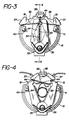
- FIG. 3 illustrates arms 18 and 19 in their closed position effectively clamping tube 11 between faces 33 and 34 respectively to seal the tube.
- Arms 18 and 19 are mounted on post 35 which forms an axis about which the arms pivot. The arms are biased toward the closed position by the action of coil spring 36.
- Clamping arms 18 and 19 are operated by urging the free end 37 of each arm toward the central axis of the valve, as illustrated in Fig. 4.
- the free end of each arm is provided with an irregular edge surface at 37 to provide a sure, slip-free grip by the thumb and forefinger of one hand of the patient.
- Each arm is further provided with detents 38 which engage boss 39 on the central axis of back plate 16 to hold arms 18 and 19 in a fully opened position against the bias of spring 36.
- Fig. 6 is a view in cross- section of the fully assembled valve body through central axis represented by line 6-6 in Fig. 3.
- Fig. 6 further illustrates the storage of the free end of the drainage tube 11 which lies in a folded configuration under cover 24.
- valve body Assembly of the valve body is facilitated by means of spacer blocks 40 and 41 which, together with boss 39 and pivot post 35, provide a four point support to space front plate 17 from back plate 16 a distance sufficient to accommodate clamping arms 18 and 19.
- Each of said four supports further includes an assembly alignment pin projecting therefrom which mates with alignment holes in front plate 17 during assembly of the unit.
- the alignment pins of back plate 16 are heat fused to front plate 17 for permanent assembly.
- cut outs 26 and 27 in sidewall 25 of cover 24 are sized and positioned to accommodate the free ends of arms 18 and 19, respectively, when the arms are in the closed position as illustrated in Fig. 3. Since the free ends of arms 18 and 19 extend slightly beyond sidewall 25 of cover 24 when the cover is positioned on the valve body, the arms are locked in the closed position until the cover is removed. The position of the free end of arm 19 in cut out 27 may be seen in Fig. 2.
- ostomy valve there may be included further clamping arm locking and alignment means such as that illustrated in the Fig. 1-6 hereof, wherein cover 24 is provided with locking pin 42 projecting from the inside surface thereof.
- Front plate 17 is provided with pin receiving aperture 43 as illustrated in Fig. 1, and clamping arms 18 and 19 are each provided with pin receiving apertures 44 which are in axial alignment when the clamping arms are in closed position as illustrated in Fig. 3.
- pin 42 extends through the apertures in the front plate and in each clamping arm to align and lock the clamping arms in the closed position.
- the security of the lock is further enhanced by providing a well 45 in back plate 16 to receive the tip of pin 42 as illustrated in Fig. 6.
- Each of clamping arms 18 and 19 is provided with offset clamping face 33 and 34, respectively, which extend laterally from one surface of the arm over the clamping area as most readily seen in Fig. 5 which illustrates arm 19 in greater detail.
- Arms 18 and 19 are identical and are assembled so that offset clamping faces 33 and 34 abut when the arms are closed thereby providing a clamping surface of substantial area across the width of the drainage tube.
- the clamping faces may be shaped to provide line contact or angled contact over the area of the clamping surface.
- the size of the ostomy valve of the present invention may be varied to accommodate different patients.
- the drainage tube 11 and balloon 12 are made of a physiologically acceptable material such as silicon rubber of the type commonly employed for medical applications.
- the tube may be on the order of 10 to 15 centimeters in length with an outer diameter of about 13 millimeters and an inner diameter of about 10 millimeters.
- the inner balloon end of the drainage tube may be rigid or semi-rigid as desired, while the outer end of the tube, which is subject to the action of the clamping arms, must be sufficiently flexible to obtain a gas-tight, water-tight seal when the clamping arms are in the closed position.
- valve body The components of the valve body, with the exception of spring means 36, are conveniently fabricated of high density polyethylene or other suitable polymeric material by injection molding.
- the valve body may have a diameter of from about 4 to 8 centimeters or larger depending on the requirements of the patient, although a diameter of 5 to 6 centimeters is suitable for most applications.
- the orifice in the valve body is sized to accommodate the drainage tube in both the open and clamped positions.
- the orifice is elongated on the vertical axis, as illustrated in Fig. 4, and has a maximum width at the horizontal axis whereby the drainage tube remains centrally oriented within the orifice of the valve body while in the open configuration.
Landscapes
- Health & Medical Sciences (AREA)
- Vascular Medicine (AREA)
- Animal Behavior & Ethology (AREA)
- Oral & Maxillofacial Surgery (AREA)
- Transplantation (AREA)
- Engineering & Computer Science (AREA)
- Biomedical Technology (AREA)
- Heart & Thoracic Surgery (AREA)
- Urology & Nephrology (AREA)
- Cardiology (AREA)
- General Health & Medical Sciences (AREA)
- Life Sciences & Earth Sciences (AREA)
- Public Health (AREA)
- Veterinary Medicine (AREA)
- Orthopedics, Nursing, And Contraception (AREA)
- Materials For Medical Uses (AREA)
- Infusion, Injection, And Reservoir Apparatuses (AREA)
- Prostheses (AREA)
Claims (10)
Priority Applications (1)
| Application Number | Priority Date | Filing Date | Title |
|---|---|---|---|
| AT86305719T ATE56610T1 (de) | 1985-07-26 | 1986-07-25 | Ventil kontinent fuer ostomie. |
Applications Claiming Priority (2)
| Application Number | Priority Date | Filing Date | Title |
|---|---|---|---|
| US06/759,545 US4634421A (en) | 1985-07-26 | 1985-07-26 | Valve for incontinent patients |
| US759545 | 1985-07-26 |
Publications (2)
| Publication Number | Publication Date |
|---|---|
| EP0223329A1 EP0223329A1 (fr) | 1987-05-27 |
| EP0223329B1 true EP0223329B1 (fr) | 1990-09-19 |
Family
ID=25056057
Family Applications (1)
| Application Number | Title | Priority Date | Filing Date |
|---|---|---|---|
| EP86305719A Expired - Lifetime EP0223329B1 (fr) | 1985-07-26 | 1986-07-25 | Valve pour ostomie continente |
Country Status (6)
| Country | Link |
|---|---|
| US (1) | US4634421A (fr) |
| EP (1) | EP0223329B1 (fr) |
| AT (1) | ATE56610T1 (fr) |
| AU (1) | AU6058286A (fr) |
| CA (1) | CA1258803A (fr) |
| DE (1) | DE3674344D1 (fr) |
Families Citing this family (75)
| Publication number | Priority date | Publication date | Assignee | Title |
|---|---|---|---|---|
| US4769004A (en) * | 1987-03-02 | 1988-09-06 | Medivators, Inc. | Flexible tubing clamp and method of use |
| US4804375A (en) * | 1987-05-06 | 1989-02-14 | Santa Barbara Medical Foundation Clinic | Ileostomy valve having a rotatable shut off |
| US5127626A (en) * | 1989-10-31 | 1992-07-07 | Applied Vascular Devices, Inc. | Apparatus for sealing around members extending therethrough |
| US5106054A (en) * | 1990-08-23 | 1992-04-21 | Thomas J. Fogarty | Self-sealing hemostasis valve apparatus and method of forming the same |
| US5083741A (en) * | 1991-05-10 | 1992-01-28 | Block Medical, Inc. | IV tube clamp with extended clamping surface |
| US6981966B2 (en) * | 1991-10-18 | 2006-01-03 | United States Surgical | Valve assembly for introducing instruments into body cavities |
| US6569120B1 (en) | 1991-10-18 | 2003-05-27 | United States Surgical Corporation | Seal assembly |
| US5201714A (en) * | 1992-03-05 | 1993-04-13 | Conmed Corporation | Laparoscopic cannula |
| US20050096605A1 (en) * | 1992-04-24 | 2005-05-05 | Green David T. | Valve assembly for introducing instruments into body cavities |
| CA2093748C (fr) * | 1992-04-24 | 1996-11-12 | Roy D. Gravener | Ensemble de valves permettant d'introduire des instruments dans les cavites du corps |
| US5387196A (en) * | 1992-05-19 | 1995-02-07 | United States Surgical Corporation | Cannula assembly having conductive cannula |
| US5413565A (en) * | 1993-01-15 | 1995-05-09 | Sandoz Nutrition Ltd. | Gastrostomy feeding port with elastic adjustable tip |
| US5389081A (en) * | 1993-05-18 | 1995-02-14 | United States Surgical Corporation | Stabilizer for a valve assembly for introducing instruments into body cavities |
| US5657963A (en) * | 1993-06-16 | 1997-08-19 | United States Surgical Corporation | Seal assembly for accommodating introduction of surgical instruments |
| US5492304A (en) * | 1993-06-16 | 1996-02-20 | United States Surgical Corporation | Seal assembly for accommodating introduction of surgical instruments |
| CA2126150C (fr) * | 1993-07-14 | 2005-02-22 | David T. Green | Montage obturateur facilitant l'introduction d'instruments chirurgicaux |
| US5569206A (en) * | 1993-09-14 | 1996-10-29 | United States Surgical Corporation | Trocar adapter seal |
| US5813974A (en) * | 1995-12-19 | 1998-09-29 | Dolade Guardia; Jose Manuel | Device for women suffering from incontinence |
| ES1032760Y (es) * | 1995-12-19 | 1996-11-01 | Guardia Jose Manuel Dolade | Dispositivo para incontinentes femeninos. |
| US7087041B2 (en) | 1998-02-25 | 2006-08-08 | Zassi Medical Evolutions, Inc. | Pad for use with continent ostomy port |
| US6033390A (en) * | 1998-02-25 | 2000-03-07 | Zassi Medical Evolutions, Inc. | Continent ostomy port |
| US6485476B1 (en) | 1998-02-25 | 2002-11-26 | Zassi Medical Evolutions, Inc. | Continent ostomy port |
| USD446580S1 (en) | 1999-11-02 | 2001-08-14 | Hector D. Allende | Anorectal apparatus |
| US6342052B1 (en) * | 1999-11-02 | 2002-01-29 | Hector D. Allende | Anorectal apparatus |
| GB9927900D0 (en) * | 1999-11-25 | 2000-01-26 | Ssl Int Plc | Medical device |
| US7001367B2 (en) * | 2002-04-16 | 2006-02-21 | Arkinstall William W | Valved ostomy drainage device |
| US6752754B1 (en) * | 2003-02-04 | 2004-06-22 | Imagine Enterprise, Inc. | Artificial rectum and related method |
| WO2004108016A1 (fr) * | 2003-06-11 | 2004-12-16 | Heike Theis | Dispositif pour obturer des poches pour stomie et dispositif pour obturer un element de fixation a appliquer sur une stomie |
| US7686825B2 (en) | 2004-03-25 | 2010-03-30 | Hauser David L | Vascular filter device |
| US9452081B2 (en) * | 2007-10-12 | 2016-09-27 | Peter Forsell | Ostomy accessory |
| US8109910B2 (en) | 2008-02-14 | 2012-02-07 | Tyco Healthcare Group Lp | Flip-top design cannula |
| US8192410B2 (en) * | 2008-08-18 | 2012-06-05 | Stephen Smith | Control device for surgical stoma |
| US8267370B2 (en) | 2008-10-28 | 2012-09-18 | Medical Components, Inc. | Clamp for flexible tubing |
| US8900116B2 (en) * | 2009-07-14 | 2014-12-02 | Stimatix Gi Ltd. | Inflatable stomal implant |
| US8864729B2 (en) | 2009-07-14 | 2014-10-21 | Stimatix Gi Ltd. | Ostomy closure |
| US8998862B2 (en) | 2009-07-14 | 2015-04-07 | B. Braun Medical Sas | Ostomy containment device |
| WO2011091481A1 (fr) | 2010-02-01 | 2011-08-04 | Saied Sabeti | Dispositif médical |
| IN2012MN02631A (fr) | 2010-05-02 | 2015-05-22 | Stimatix Gi Ltd | |
| EP2856985B1 (fr) | 2010-05-02 | 2017-11-22 | B.Braun Medical SAS | Bouchon de stomie jetable |
| US8807517B2 (en) * | 2010-12-01 | 2014-08-19 | Nelson Irrigation Corporation | Rotary pinch valve |
| WO2013168165A2 (fr) | 2012-05-10 | 2013-11-14 | Stimatix Gi Ltd. | Appareillage pour stomie |
| WO2014181338A2 (fr) | 2013-05-09 | 2014-11-13 | Stimatix Gi Ltd. | Appareillage stomique compact |
| CN103405297A (zh) * | 2013-08-27 | 2013-11-27 | 林建江 | 完全转流型肠造瘘管 |
| WO2015061365A1 (fr) | 2013-10-21 | 2015-04-30 | Inceptus Medical, Llc | Procédés et appareil de traitement d'embolie |
| USD783814S1 (en) | 2013-12-09 | 2017-04-11 | B. Braun Medical Sas | Adapter for flatus release |
| USD796029S1 (en) | 2013-12-09 | 2017-08-29 | B. Braun Medical Sas | Colostomy appliance |
| US10441455B2 (en) * | 2015-04-02 | 2019-10-15 | Mayo Foundation For Medical Education And Research | Continent ostomy valve and method of use |
| CN108472052B (zh) | 2015-10-23 | 2021-10-01 | 伊纳里医疗公司 | 脉管闭塞的脉管内治疗以及相关的装置、系统和方法 |
| CN108135591B (zh) | 2016-02-24 | 2021-05-28 | 禾木(中国)生物工程有限公司 | 柔性增强的神经血管导管 |
| DE102016208677A1 (de) * | 2016-05-19 | 2017-11-23 | B. Braun Melsungen Ag | Durchflussregeleinrichtung für eine Schlauchleitung eines medizinischen Infusionssystems |
| CN110312481B (zh) | 2016-10-24 | 2023-04-11 | 伊纳里医疗有限公司 | 用于治疗血管闭塞的装置和方法 |
| US10349929B2 (en) * | 2017-03-24 | 2019-07-16 | Medos International Sarl | Cannula with cap |
| ES3008609T3 (en) * | 2017-09-06 | 2025-03-24 | Inari Medical Inc | Hemostasis valves and methods of use |
| US12178738B2 (en) * | 2018-01-19 | 2024-12-31 | Ostovalve Llc | Regulating flow from a stoma on a patient |
| US11771585B2 (en) * | 2018-01-19 | 2023-10-03 | Ostovalve, Llc | Devices, systems and methods for regulating flow from a stoma on a patient |
| US11154314B2 (en) | 2018-01-26 | 2021-10-26 | Inari Medical, Inc. | Single insertion delivery system for treating embolism and associated systems and methods |
| GB201806045D0 (en) * | 2018-04-12 | 2018-05-30 | Ostomycure As | Lid |
| US10863839B1 (en) | 2018-07-21 | 2020-12-15 | Edward Conrad, Jr. | Protective cover for pop-up straw |
| ES3000010T3 (en) | 2018-08-13 | 2025-02-27 | Inari Medical Inc | System for treating embolism and associated devices and methods |
| US20200155338A1 (en) * | 2018-11-19 | 2020-05-21 | Karla K. Meteer | Prosthetic stoma device and method of application |
| US12220383B2 (en) | 2018-11-27 | 2025-02-11 | The Regents Of The University Of Colorado | Securement assembly for enteral and vesical access devices and related methods |
| USD1012280S1 (en) | 2018-11-30 | 2024-01-23 | B. Braun Medical Sas | Ostomy device assembly |
| US11766539B2 (en) | 2019-03-29 | 2023-09-26 | Incept, Llc | Enhanced flexibility neurovascular catheter |
| CA3157521A1 (fr) | 2019-10-16 | 2021-04-22 | Inari Medical, Inc. | Systemes, dispositifs et procedes de traitement d'occlusions vasculaires |
| US11457936B2 (en) | 2019-12-18 | 2022-10-04 | Imperative Care, Inc. | Catheter system for treating thromboembolic disease |
| EP4093344B1 (fr) * | 2020-03-16 | 2024-06-12 | Legna Medikal Teknoloji Sanayi Ve Ticaret Anonim Sirketi | Système urinaire rendant volontaire l'excrétion involontaire se produisant après colostomie, iléostomie et urostomie |
| AU2021283979A1 (en) | 2020-06-05 | 2023-01-19 | Stryker Corporation | Recapturable funnel catheters, and associated systems and methods |
| US12364496B2 (en) | 2022-01-11 | 2025-07-22 | Inari Medical, Inc. | Devices for removing clot material from intravascularly implanted devices, and associated systems and methods |
| JP2025503965A (ja) | 2022-02-08 | 2025-02-06 | イナリ メディカル, インコーポレイテッド | 拡張器係止機構を有する凝塊治療システム、並びに関連するデバイス及び方法 |
| EP4498997B1 (fr) * | 2022-04-22 | 2025-07-23 | OstomyCure AS | Couvercle pour un implant de stomie |
| AU2024207180A1 (en) | 2023-01-09 | 2025-07-17 | Stryker Corporation | Catheter for use with clot treatment systems |
| US12558486B2 (en) | 2023-11-16 | 2026-02-24 | Inari Medical, Inc. | Automatic locking and unlocking vacuum syringes, and associated systems and methods |
| US12171917B1 (en) | 2024-01-08 | 2024-12-24 | Imperative Care, Inc. | Devices for blood capture and reintroduction during aspiration procedure |
| WO2025178639A1 (fr) * | 2024-02-23 | 2025-08-28 | Imperative Care, Inc. | Valve hémostatique |
| US12465382B1 (en) | 2024-05-10 | 2025-11-11 | Inari Medical, Inc. | Mechanical thrombectomy assemblies with relief features, and associated devices, systems, and methods |
Family Cites Families (11)
| Publication number | Priority date | Publication date | Assignee | Title |
|---|---|---|---|---|
| US788553A (en) * | 1905-01-21 | 1905-05-02 | Frederic G Nicolaus | Receptacle-closer. |
| US3279656A (en) * | 1965-01-04 | 1966-10-18 | Container Corp | Dispensing control for a bag-in-box arrangement |
| US3952726A (en) * | 1973-12-20 | 1976-04-27 | Gerhard R. Hennig | Medical device |
| DE2618718C2 (de) * | 1976-04-28 | 1986-11-06 | Urocare Products, Inc., South El Monte, Calif. | Schließelement für ein Rückschlagventil und damit versehenes Rückschlagventil für eine Urinsammelvorrichtung |
| US4114640A (en) * | 1977-01-10 | 1978-09-19 | Will Ross Inc. | Drain valve |
| DE2717607C3 (de) * | 1977-04-20 | 1981-06-25 | Coloplast A/S, Espergaerde | Magnetverschlußstopfen für einen Darmausgang |
| DE2843930C3 (de) * | 1978-10-09 | 1981-07-02 | Otto 6509 Flonheim Knell | Verschlußdeckel mit Mittelstift zum Verbinden eines künstlichen Darmausgangs |
| US4351322A (en) * | 1980-10-10 | 1982-09-28 | Prager Elliot D | Stoma control device and method |
| US4381765A (en) * | 1981-04-02 | 1983-05-03 | Waters Instruments, Inc. | Ileostomy valve |
| US4474182A (en) * | 1981-10-05 | 1984-10-02 | Herman Rea | Surgical Stoma Tool and methods of making and using the same |
| FR2528693B1 (fr) * | 1982-06-22 | 1985-01-11 | Mabille Pierre | Appareil de prophylaxie dentaire |
-
1985
- 1985-07-26 US US06/759,545 patent/US4634421A/en not_active Expired - Lifetime
-
1986
- 1986-07-24 CA CA000514549A patent/CA1258803A/fr not_active Expired
- 1986-07-25 DE DE8686305719T patent/DE3674344D1/de not_active Expired - Lifetime
- 1986-07-25 AU AU60582/86A patent/AU6058286A/en not_active Abandoned
- 1986-07-25 EP EP86305719A patent/EP0223329B1/fr not_active Expired - Lifetime
- 1986-07-25 AT AT86305719T patent/ATE56610T1/de not_active IP Right Cessation
Also Published As
| Publication number | Publication date |
|---|---|
| US4634421A (en) | 1987-01-06 |
| CA1258803A (fr) | 1989-08-29 |
| EP0223329A1 (fr) | 1987-05-27 |
| ATE56610T1 (de) | 1990-10-15 |
| AU6058286A (en) | 1987-01-29 |
| DE3674344D1 (de) | 1990-10-25 |
Similar Documents
| Publication | Publication Date | Title |
|---|---|---|
| US4634421A (en) | Valve for incontinent patients | |
| US5125916A (en) | Stoma cap | |
| US4338937A (en) | Mechanical continent ileostomy or colostomy | |
| EP0168967A1 (fr) | Prothèse d'ostomie | |
| US6595971B1 (en) | Ostomy irrigation system | |
| US4200102A (en) | Baby hygienic receptor | |
| AU2011208954B2 (en) | Medical device | |
| US5261898A (en) | Temporary colostomy apparatus | |
| US4790833A (en) | Bag of plastic film for collecting discharges from human or animal bodies via drains | |
| EP0747026B1 (fr) | Dispositif auto-aligné pour stomie | |
| US6679867B2 (en) | Male incontinence device | |
| US4210131A (en) | Artificial sphincter with collection bag | |
| EP0062468A2 (fr) | Soupape iléostomique | |
| US20120136324A1 (en) | Ostomy containment device | |
| BR112014028052A2 (pt) | aparelho para ostomia, sistema de vedação do componente de ostomia, e método de vedação do estoma no corpo de um indivíduo. | |
| BRPI0501989B1 (pt) | orifício de injeção cirúrgico implantável | |
| MXPA04003529A (es) | Sistema de manejo intestinal. | |
| US20120123362A1 (en) | Urostomy bag cover systems | |
| EP1365807B1 (fr) | Receptacle | |
| AU2002215286A1 (en) | Receptacle | |
| WO2019202605A1 (fr) | Dispositif polyvalent d'occlusion et de distension vaginale doté d'un dispositif de commande de distension | |
| US4217899A (en) | Colonic endoprosthesis | |
| CN110251270A (zh) | 一种肛门护理器 | |
| CN223232935U (zh) | 一种造口收纳包 | |
| US20250143912A1 (en) | Ostomy pouch with viewing option window |
Legal Events
| Date | Code | Title | Description |
|---|---|---|---|
| PUAI | Public reference made under article 153(3) epc to a published international application that has entered the european phase |
Free format text: ORIGINAL CODE: 0009012 |
|
| AK | Designated contracting states |
Kind code of ref document: A1 Designated state(s): AT BE CH DE GB LI NL |
|
| 17P | Request for examination filed |
Effective date: 19871105 |
|
| 17Q | First examination report despatched |
Effective date: 19891005 |
|
| GRAA | (expected) grant |
Free format text: ORIGINAL CODE: 0009210 |
|
| AK | Designated contracting states |
Kind code of ref document: B1 Designated state(s): AT BE CH DE GB LI NL |
|
| REF | Corresponds to: |
Ref document number: 56610 Country of ref document: AT Date of ref document: 19901015 Kind code of ref document: T |
|
| REF | Corresponds to: |
Ref document number: 3674344 Country of ref document: DE Date of ref document: 19901025 |
|
| PLBE | No opposition filed within time limit |
Free format text: ORIGINAL CODE: 0009261 |
|
| STAA | Information on the status of an ep patent application or granted ep patent |
Free format text: STATUS: NO OPPOSITION FILED WITHIN TIME LIMIT |
|
| PG25 | Lapsed in a contracting state [announced via postgrant information from national office to epo] |
Ref country code: GB Effective date: 19910725 |
|
| PG25 | Lapsed in a contracting state [announced via postgrant information from national office to epo] |
Ref country code: BE Effective date: 19910731 |
|
| 26N | No opposition filed | ||
| BERE | Be: lapsed |
Owner name: JOHNSON & JOHNSON PRODUCTS INC. Effective date: 19910731 |
|
| PG25 | Lapsed in a contracting state [announced via postgrant information from national office to epo] |
Ref country code: NL Effective date: 19920201 |
|
| NLV4 | Nl: lapsed or anulled due to non-payment of the annual fee | ||
| GBPC | Gb: european patent ceased through non-payment of renewal fee | ||
| PGFP | Annual fee paid to national office [announced via postgrant information from national office to epo] |
Ref country code: AT Payment date: 19920714 Year of fee payment: 7 |
|
| PGFP | Annual fee paid to national office [announced via postgrant information from national office to epo] |
Ref country code: DE Payment date: 19920727 Year of fee payment: 7 Ref country code: CH Payment date: 19920727 Year of fee payment: 7 |
|
| PG25 | Lapsed in a contracting state [announced via postgrant information from national office to epo] |
Ref country code: AT Effective date: 19930725 |
|
| PG25 | Lapsed in a contracting state [announced via postgrant information from national office to epo] |
Ref country code: LI Effective date: 19930731 Ref country code: CH Effective date: 19930731 |
|
| REG | Reference to a national code |
Ref country code: CH Ref legal event code: PL |
|
| PG25 | Lapsed in a contracting state [announced via postgrant information from national office to epo] |
Ref country code: DE Effective date: 19940401 |