EP0223356A2 - Funduskamera mit zweidimensionaler Abtastung - Google Patents
Funduskamera mit zweidimensionaler Abtastung Download PDFInfo
- Publication number
- EP0223356A2 EP0223356A2 EP86307101A EP86307101A EP0223356A2 EP 0223356 A2 EP0223356 A2 EP 0223356A2 EP 86307101 A EP86307101 A EP 86307101A EP 86307101 A EP86307101 A EP 86307101A EP 0223356 A2 EP0223356 A2 EP 0223356A2
- Authority
- EP
- European Patent Office
- Prior art keywords
- scanning
- ophthalmoscope
- optical
- reflected
- laser beam
- Prior art date
- Legal status (The legal status is an assumption and is not a legal conclusion. Google has not performed a legal analysis and makes no representation as to the accuracy of the status listed.)
- Granted
Links
Images


Classifications
-
- A—HUMAN NECESSITIES
- A61—MEDICAL OR VETERINARY SCIENCE; HYGIENE
- A61B—DIAGNOSIS; SURGERY; IDENTIFICATION
- A61B3/00—Apparatus for testing the eyes; Instruments for examining the eyes
- A61B3/10—Objective types, i.e. instruments for examining the eyes independent of the patients' perceptions or reactions
- A61B3/1025—Objective types, i.e. instruments for examining the eyes independent of the patients' perceptions or reactions for confocal scanning
Definitions
- This invention relates in general to optical instruments and methods, and more particularly to an instrument for scanning a surface or other structure with an optical beam, detecting the light emitted from the structure, and generating a two-dimensional representation of an image of the structure.
- One such instrument is a scanning ophthalmoscope which produces an image of the fundus of the eye. It has been found that the use of a laser light source provides improved imaging in an ophthalmoscoope.
- a laser scanning ophthalmoscope is described in U.S. Patent No. 4,213,678.
- One problem associated with ophthalmoscopes of the type described in U.S. Patent 4,213,678 is that the light collected, at the time the laser is illuminating a particular area on the retina, includes not only light reflected directly from that area, but also light scattered from other surfaces and materials within the eye. This scattered light can cloud or fog the image, since it represents light contributions from other than the specific illuminated area.
- each small illuminated area of the target object being examined produces a corresponding image area in the output display, with a brightness or intensity related only to light reflected directly from that target area.
- the scattered light by itself to the degree that it can be separated from the light directly reflected from the illuminated target area, is useful for diagnostic purposes.
- the entrance pupil for the scanning laser beam has a small cross sectional area within the pupil of the eye, typically 0.5 mm in diameter, whereas the exit aperture for the reflected light is the overall pupil of the eye, which typically is nine mm in diameter.
- the detector is placed in a plane conjugate to this exit aperture.
- the scanning is effected by deflection galvanometers.
- the horizontal galvanometer is driven at 15.75 kHz in order to match the horizontal scan frequency of a conventional television sweep, which preferably is used to display the output image.
- the vertical galvanometer is driven at 60 Hz to produce 525 lines per frame of the output image, again corresponding to the generation of a conventional television raster.
- the resolution in the raster display of the retinal image directly corresponds to the cross sectional area of the laser spot as it scans the retina.
- the contrast of the ultimate image depends, at least in part, upon the proportion of light received by the detector which is directly reflected from the illuminated area.
- scattered light indirectly reaches the detector at the same time as it receives the light directly reflected from the illuminated area, the image is fogged and the contrast is reduced.
- reflected is used herein in a broad sense to refer to all optical energy returned by the target structure, it hence includes returned optical energy that results from both specular and diffuse reflection.
- the optical system is arranged to provide that the light reflected from the illuminated target area is selected with a scanning-like action related to the scanning of the incident illumination in such a manner that, at a given instant, the reflected light received by the detector is only that which is reflected from the illuminated target area.
- the fundus conjugate plane thereby allowing discrimination, at the conjugate retinal plane, between the light directly reflected from the retinal locus and that scattered either anteriorly or posteriorly, i.e. within the retina.
- Another deflection element which has been used for scanning optical instruments is a multifaceted rotating polygon, which would have to rotate at sufficiently high speeds to produce a horizontal scan matching the television frequencies.
- the size of the facet required to encompass the image received from the eye's exit aperture is prohibitively large in terms of fabricating a polygonal reflector to rotate at the required speeds.
- the acousto-optical deflector is also not available in a form considered suitable for the reflected beam in such an instrument, due to aperture limitations.
- the image is created in response essentially to directly reflected light; and in another embodiment in response to indirectly reflected light.
- a double scanning optical instrument can be constructed utilizing a laser source and a multifaceted polygonal reflector for horizontal scan, with a reflection galvanometer or other scanning element for vertical scan, where the facet size in the direction of scan for the polygonal reflector is necessarily small and the reflected beam from the exit aperture of the system is substantially larger than that facet dimension.
- the small facets of the polygonal reflector intercept less than 20% of the reflected light from the exit aperture.
- an optical instrument of the type which responds to light energy responsive to a scanned incident beam, can be provided with double scanning with at least one scan element having such a small size that the exit beam overfills it. That is, this scan element is of such small size that it intercepts only a portion of the exit beam.
- the double-scanning instrument attains images having significant improvements over those of prior instruments.
- An instrument according to the invention attains this improved performance even when configured to have a large optical exit aperture, as is often desired.
- the present invention is a scanning ophthalmoscope for providing a two-dimensional output representation of reflection characteristics of the eye fundus, said apparatus comprising, a laser source for generating a laser beam of defined cross sectional area which is small compared to an area of the fundus which is to be scanned and to the pupil of the eye, an optical system for directing said laser beam through the pupil of the eye onto said fundus area, said optical system including, a first scanning element comprising a rotatable element having spaced facets for changing the direction of an incident laser beam and driving means for rotating said reflector to scan said laser beam along a first coordinate across an area of said fundus, reflective means for directing said laser beam from said first scanning element through approximately the centre of the eye pupil onto the fundus area, an exit aperture for reflected light from said scanned fundus area, said exit aperture being large compared to the beam cross section dimension, said reflective means being positioned to produce at the facet of said first scanning element a conjugate image of said eye pupil, a detector, beam separating means positioned to direct
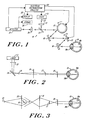
- FIGURE 1 shows an embodiment of the invention in the form of an ophthalmoscope 10.
- a laser illumination source 11 produces a narrow incident light beam 12 which passes through a shaping lens system 13 which produces a slightly converging b eam that impinges on a small turning mirror 14.
- the mirror 14 directs the incident laser beam onto facets of a multi-faceted rotating polygonal reflector scanner 15, which provides a horizontal scanning motion of the incident beam.
- the incident beam is reflected from this first stage scanning element onto a focusing mirror 16, which directs the beam onto the reflecting surface of a galvanometer reflector scanner 17 to produce a vertical scanning motion.
- the laser input beam is directed onto a second focusing mirror 18, for focusing it onto the fundus 19 a of the eye 19 of a subject.
- the incident beam enters the eye at the crystalline lens 19 b .
- the reflected light from the fundus 19 is directed back over a common portion of the foregoing optical input path, which includes focusing mirror 18, the second stage scanner 17, focusing mirror 16 and the first stage scanner 15. All of these common elements are mirrors and hence do not contribute reflections of the input beam back to the detector as noise background.
- the reflected output beam from the first stage scanner 15 in large part passes by the turning mirror 14 and hence separates from further traverse along the incident optical path.
- the output beam instead is directed through a focusing lens 20 and onto an optical detector 21.
- the detector 21 is electrically connected to an electrical instrumentation unit 22 which provides electrical control signals to the laser source 11 and electrical drive signals to the scanning deflection elements 15 and 17.
- the instrumentation unit provides synchronization of the signals received at the scanning elements 15 and 17 so that the temporal order of the signals produced by the detector 21 can be correlated with the location of the scanned incident laser beam on the surface of the fundus.
- the control and synchronization which the instrumentation unit provides enables a two-dimensional display device 23, such as a television raster device, to form a two-dimensional display of an image of the eye fundus 19 a , in response to the electrical signal which the detector produces in response to the reflected optical energy it receives.
- the detector signal may be applied to a long term storage element 24, such as a video tape recorder, for subsequent readout and display.
- a long term storage element 24 such as a video tape recorder
- the laser 11 can be any suitable laser light source which provides emission at frequencies yielding appropriate contrast for the fundus, or other target.
- the laser 11 is an Argon-Krypton laser or Helium-Neon laser operated at a power level to produce an illumination irradiance of 100 microwatts per square centimeter at the fundus.
- the laser 11 may also be selected to emit in the infrared wavelength region to provide a scanning beam which does not require that the eye pupil be medically dilated to obtain an image of the fundus.
- two lasers of different wavelengths may be employed and converted into a single beam with a dichroic beam splitter.
- FIGURE 7 illustrates a modification to the embodiment of FIGURE 1 in which additional elements are inserted between the laser 11 and the horizontal scanner 15.
- This embodiment includes an acousto-optic modulator (AOM) 30 for performing the graphic imaging function.
- AOM acousto-optic modulator
- the AOM receives a control input from a program control unit 34, which is typically a computer programmed to provide a signal timed to direct the laser beam emerging from the AOM away from the scanning path, thus blanking the scanning beam appropriately, to produce the image, a suitable comput er being an IBM PC-XT made by International Business Machines, Yorktown Heights, New York with a Revolution 512 x 8 graphics peripheral card with gen lock, made by Number Nine Computer, Cambridge, Massachusetts.
- a program available for the graphic control is Media Cybernetics' Halo, by Media Cybernetics of Takoma Park, Md.
- a visible graphic image may also be provided when an infrared laser is employed, by utilizing n incandescent light beam incident on the AOM.
- the incandescent source will have sufficient intensity to stimulate the patient's retina but will not affect the scanned output image.
- Prisms 32 are placed in the beam between the laser and the AOM and after the AOM to allow lasers of different wavelengths to be used, while preserving the same Bragg angle relationship for the different wavelengths within the AOM to maintain the output beams from the AOM on the same optical axis.
- FIGURE 8 is a block diagram of the acousto-optic modulator.
- the acousto-optic modulator includes a driver unit 40 coupled to a transducer unit 41.
- the driver unit 40 includes an RF oscillator 42 typically operating at 40 MHz, followed by a buffer 46 which couples the oscillator to a balanced modulator 47.
- the output from the balance modulator 47 is coupled through an RF power amplifier 48 as the modulated RF output to the transducer element 41.
- the transducer element 41 is typically a glass crystal having Piezoelectric elements bonded to it to produce acoustic waves in the glass crystal. Optical waves incident on this crystal are then diffracted when the balanced modulator provides an output and remain undiffracted when there is no output from the balanced modulator, that is when the output from the driver 40 is blanked.
- the driver and transducer unit is commercially available from IntraAction Inc of Bellewood, Illinois, under the trade designation AEM40 & MOP402B.
- AEM40 & MOP402B a video input is provided to the balanced modulator 47 thus controlling the output signal to effect the optical modulation; control signals are applied to this input from the graphics program control.
- a blanking input to the balanced modulator must be presented at times, not directly associated with the presentation of the graphics, in order completely to turn off the laser beam during the retrace of the display raster. This is done so that the laser beam does not impinge upon the patient's eye during this period, thus avoiding unnecessary irradiation of the patient's eye on distractingly visible retrace lines.
- a retrace blanking signal is provided directly to buffer 46 to decouple the RF oscillator output 42 from the balanced modulator 47, thus disabling the driver unit 40 during this period.
- the AOM diverts some of the beam energy into a first order (Bragg diffraction) beam at an angle typically about 15 mradians from the zero order beam. Either the original beam or the diffracted beam can be used to form the flying spot on the retina and its intensity is controllable over about three orders of magnitude by the AOM drive.
- the Bragg diffraction on which the modulation depends is from acoustic waves in a glass, of frequency 40 to 100 MHz. Two complicatons occur: because this is diffraction, it is inherently chromatic; and modulation of a high frequency carrier introduces other frequency components.
- the chromaticity is compensated with prisms 32 placed around the AOM. This brings both red and green beams to the glass at their preferred Bragg angles.
- the second prism is after the AOM to cause the beams to exit together, but the t risms can be combined into one without serious problems. Minor adjustment at the combining dichroic beam splitter brings the two rasters into perfect alignment.
- the purpose of the input optical system is to scan the fundus with a narrow optical beam to sequentially illuminate small segmental areas across the fundus surface in a known pattern so that the reflected light detected in time sequence can be electrically converted to a two-dimensional representation of the reflection characteristics of the fundus.
- the input optical system forms the incident laser beam with a cross sectional area of substantially 0.5 mm diameter at the entrance pupil of the eye and focussed on the fundus to produce a spot approximately twelve microns in diameter.
- the horizontal scanning motion in the illustrated preferred embodiment is provided by a rotational scanner which is shown in the preferred embodiment as a multi-faceted polygonal reflector scanner 15 which is rotated by an electric motor at speeds sufficient to produce a scanning frequency of 15.75 kHz to be compatible with a TV sweep frequency.
- a polygon of (m) facets turns the incident laser beam through a scan angle of 720/m degrees.
- it must rotate at 40,000 rpm in order to generate the 15.75 kHz scanning frequency.
- the moment of inertia of the polygon must be kept small.
- each facet is six mm wide.
- the polygonal rotating reflector of the scanner 15 can be obtained commercially from Lincoln Laser, Pheonix, Arizona, No. PO-24 (A Grade, G Grade).
- a holographic disk scanner such as made by Holotech, Inc., which has spaced holographic facets may be substituted for this polygon reflector.
- the scan angle can be changed optically by any of the subsequent optical elements.
- One approach to modifying the field of view is to set the vertical manner to the same 28.8 degrees and then to modify the whole field of view at once. Resolution depends on the ratio of scan aperture to scan angle, so proper optical modification after the scan preserves the original resolution. With an input beam diameter of about 1 mm at the polygon, the available resolution is 794 spots, of which only 667 are used because of the 84% TV duty cycle.
- the field of view can be increased or decreased by simple optical magnification. Increase of the field results in concurrent decrease of the beam diameter at the pupil, and this increases the spot size at the retina, so the resolution is unchanged.
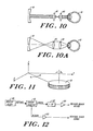
- FIGURE 10 is an illustration of the beam diagram of this system while FIGURE 10A illustrates the return reflection envelope.
- lenses 40 and 41 are placed between the eye pupil and the mirror 18.
- Lens 40 is typically a 28-diopter ophthalmoscope lens and lens 41 may be a 14-diopter ophthalmoscope lens.
- the field of view can be made sm aller. If the distance between lenses 40 and 41 is adjusted to be unequal to the sum of the lenses' focal length, then refractive errors in the patient's eye can be compensated.
- An advantage of this arrangement is that the telescope spacing adjusts beam focus, providing an independent compensation for patients' refractive error.
- This telescope system does, however, produce reflections.
- Four refractive surfaces intercept the incoming laser beam and reflect it back to the detector. Some of these reflections can be blocked by appropriately placed stops and some can be diminished or displaced by suitable choice of surface bend and tilt.
- the residuum can at least be localized to one small area of the picture. Since it is a moving picture, the clinician can easily look around such a single reflection.
- the reflections substantially vanish, so that it is only in the afocal mode that they are a problem.
- Another method of changing the field size avoids these problems: element 18 can be placed in a position to increase or decrease the field at the retina. This is inconvenient to implement, but is a preferred embodiment if reflections are a problem.
- the vertical scanning motion in the illustrated preferred embodiment is introduced by a deflection galvanometer 17 that provides a scan action which corresponds with the television vertical scan of 60 Hz.
- Galvanometer controls such as those manufactured by General Scanning of Watertown, Massachusetts, are suitable for driving and controlling the position of the galvanometer mirror.
- the mirror 17 can, for example, be a type G120D General Scanning mirror.
- the illustrated laser beam of 0.5 mm in diameter which it produces underfills each mirror facet of the polygon scanner 15, which, in the same illustrative embodiment, is six mm wide.
- the beam scanning pivots about a point in the plane of the eye's pupil.
- the laser beam must be in focus at the retina, and the scan waist must be located (approximately) at the eyes of the pupil. Under these circumstances the spot size is appropriate for the available resolution, and the image will appear in focus at the TV screen even if it is not in focus at the confocal aperture. It is the focus of the incident beam which determines the picture's resolution and the focus of the return beam (at the confocal stop) which controls contrast. The fact that these controls are largely orthogonal is what allows flexibility as to mode of view.
- the turning mirror 14 preferably is a stationary mirror reflector. It is small in size in order to produce a minimal shadow in the output beam, and hence preferably is only large enough to intercept the input beam which the focusing element 13 directs, via the turning mirror, to the first stage scanner 15. In the configuration shown the turning mirror acts as the beam separater between the input and reflected return beam.
- the laser beam is originally directed toward the polygon scanner 15.
- a mirror 38 with a central hole allows the laser beam to pass through it.
- the return reflected beam from the scanner 15 is then reflected by the annular portion of mirror 38 to the detector 21.
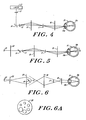
- FIGURES 2 and 4 illustrate features of the input optical system.
- FIGURE 2 represents the input beam with the scanners assumed to be stationary in a neutral, non-deflecting, position.
- the narrow collimated incident beam 12 from the laser is, in this partial representation, shaped by the optical elements 13, 14, 16 and 18, aside from the eye 19 of the subject.
- the incident beam is in focus at the retina 19 a .
- the limiting aperture formed in this instance by the entrance pupil of the eye 19 is conjugate at the scanners 15 and 17.
- FIGURE 4 which represents scan features of the input system, illustrates the input beam instantaneously as a single ray which each scanning element moves, as a function of time.
- the drawing shows, in effect, a time exposure.
- the beams intersect at the scanners and their conjugates, which, for the scanned input beam includes the entrance pupil.
- the scan angle is the full angle of this envelope in the plane of the scan.
- the mirror 18 is large and spherical. Large, so that even at f/2 (for the scan) the eye's pupil is far back from the optics. With human subjects there are some inflexible dimensions.
- the mirror is spherical because no aspheric is correct for both beam and scan systems at all points. That constraint can be understood by noting that the beam on one side of this mirror may be always collimated, no matter where it hits the mirror. So the mirror must have everywhere the same local curvature - which implies a sphere. Since the mirror is used off-axis, the scan system is then astigmatic.
- the scan system astigmatism can be corrected by adjusting the separation between the horizontal and vertical scanners along the system's optic axis.
- the small spherical mirror 16 is used as a relay between the two scanners, for more flexibility. This mirror only focuses a line scan, so it can be tilted in the orthogonal plane, contributing no astigmatism. Both mirrors contribute coma, of course, so tilt angles are kept small.
- the output optical system has a common optical path with the input system.
- This common path includes both of the scanning elements 15 and 17. In the illustrated instrument, it also includes the two focussing elements 16 and 18.
- the light reflected from facets 15 a of the rotating polygon scanner 15 passes around the turning mirror 14 and is incident on the detector optical system, which includes lens 20 and detector 21.
- FIGURE 3 represents the output beam without regard to the scanning elements 15 and 17, i.e. in the same manner as the representation in FIGURE 2.
- the reflected beam from the fundus has an exit aperture large compared to the cross section of the scanning beam, preferably substantially the entire pupil of the eye, with a diameter of as much as nine mm.
- the image of this aperture at its conjugate plane also is nine mm. Absent magnification, the reflected output beam from the illuminated area on the fundus likewise is approximately nine mm in diameter at any conjugate of the exit pupil, which is where the scan elements 15 and 17 are located.
- the central region of the eye's pupil is used as an entrance pupil and the remaining annulus an exit pupil, thus conforming to Gulstrand's principle.
- the scanners, optically conjugate to the pupil need to be big enough to intercept that larger return beam.
- a 10 - 15 mm mirror is suitable for the vertical scanner which moves as a 60 Hz sawtooth.
- the available aperture (the facet) both rotates with respect to the beam and moves across it.
- the incident 1 mm beam and a 6 mm facet on the polygon combine to give just about the 84% duty cycle required for a TV raster.
- the return beam may be as much as 15 mm in diameter, overfilling the facet even at the centre of its sweep. This does lose light, but the facet is filled with signal light over most of its duty cycle, and therefore a very uniform fraction of the light from the annular exit pupil is recovered.
- the ophthalmoscope 10 can have a small entrance pupil, as described above, due to the large radiance of the incident beam.
- the output beam has relatively low radiance, and hence the provision of this large output pupil is desired to collect a maximal amount of output light energy.
- the large exit aperture hence enhances the high efficiency of the instrument. It also facilitates viewing a large portion of the eye fundus.
- FIGURE 3 also illustrates, with exaggerated scale, that the output beam passes around the turning mirror 14, which hence casts a small shadow generally of low significance.
- FIGURE 5 represents scan aspects of the output beam, in the same manner as the scanned input beam representation in FIGURE 4.
- the scanned output rays intersect, and the envelope of the scanned rays has minimal cross-section, at the pupillary plane of the eye 19 and at the scanning elements 15 and 17; this is the same as for the scanned input beam, FIGURE 4.
- the former is at the plane of the exit pupil and the latter are at planes conjugate to it.
- the relatively large cross-section of the output beam overfills each facet on the polygonal reflector scanner 15.
- this overfill corresponds to a loss of throughput of approximately 80%.
- the reflected output light beam which the scanners 15 and 17 direct to the detector 21 is directly reflected substantially exclusively from the illuminated segmental area of the fundus.
- the detector 21 hence receives a minimal level of scatter or other unwanted light energy.
- the placement in the instrument 10 of the detector 21 at the retinal conjugate plane, as apparent in FIGURE 3, is advantageous because it allows the detector to have a small aperture.
- Optical detectors of this type have numerous advantages over large-aperture detectors.
- an avalanche diode detector 21 is highly suitable for use as the detector in this system.
- FIGURES 6 and 6A illustrate an alternative embodiment in which a diaphragm stop 26 is placed in the return beam path at the retinal conjugate plane and the detector 21 is moved to the pupillary conjugate plane.
- the envelope of the return beam is diagrammed.
- the diaphragm stop 26 can be formed as a disk with varying size openings (as illustrated in FIGURE 6A) so that the size of the diaphragm stop 26 may be varied.
- Detectors are best placed at pupillary conjugates, since pupils tend to be about detector size (a few millimeters) while the retinal spot size is likely to be ten times smaller.
- the detector of choice is a semiconductor, typically a 1 mm avalanche diode with an integral amplifier such as RCA C30950E (RCA, Ste Anne de Bellvue, Quebec, Canada).
- RCA C30950E RCA, Ste Anne de Bellvue, Quebec, Canada.
- the retinal conjugate plane can be used for the placement of the aperture which limits the amount of retinal surface the detector receives light from. Since the retinal conjugate is a magnification (about ten times) of the retina a 1 mm aperture at the retinal plane restricts the retinal area seen to approximately 0.1 mm. On the other hand, if the aperture is made 10 mm, the retinal area seen is so much larger than the illuminating spot that the system is really afocal.
- a third option of invest is to use a 10 mm aperture with a central 1 mm stop, giving a "dark field" view of the retina, in which only light indirectly reflected is detected.
- a rotatable aperture disk 26 as shown in FIGURE 6A the view can be varied from tightly confocal to afocal or dark field.
- the same disk can be arranged to carry filters for various wavelengths.
- a simple 10X microscope objective (not shown) can be used to bring the pupil back down to 1 mm for a match to the avalanche diode.
- the polygonal reflector 15 is f ormed with twenty-five facets, distortions due to facet-to-facet and other variations remain stationary in the displayed raster image, since it is evenly divisible into 525 television lines. For this reason, it is deemed preferable that the polygonal scanner have a number of reflective facets equal to an integral multiple of twenty-five. For different raster scan frequencies, a different number of facets would be appropriate. The controlling factor is that the number of reflecting facets should be integrally divisible into the number of raster lines. Further, as described above, there is a common optical path from the horizontal scanner 15 to the target object (in this example, the fundus of the eye) for the scanning beam and for the reflected light. Under these circumstances any reflection of the input laser beam from elements in the common optical path will appear as a noise signal to the detector. Accordingly, the focussing elements 16 and 18, as well as scanning elements 15 and 17, are front-surface mirrors.
- While the instrument 10 has been described in terms of the advantages of de-scanning to produce signals corresponding only to light reflected directly from the illuminated target area, there are situations in which it is advantageous to look only at indirectly reflected light. This can be accomplished by moving the detector off the optical axis of the system so that it is in effect looking at target areas displaced from the direct illumination of the input beam. It has been found that information provided from these reflections also is useful in determining characteristics of an eye fundus.
- An alternative arrangement for attaining this reponse to only indirect illumination is to image on the detector a target area concentric with, and larger than, the illuminated area, and to mask light reflected from the illuminated area, e.g. with a dark-field or central stop.
- the plane of the image can be moved to positions anterior to the retinal surface and thus various types of floaters, such as vitreous spots and strands may become visible in the image.
- movement of the image plane to posterior, sub-surface positions enables the instrument to image interior structure of the eye fundus.
- the 15.75 kHz horizontal scan frequency and the 60 Hz vertical scan frequency described above for the illustrated embodiment are for use with television standards adopted for the USA. These values can be selected to suit other standards in practice in other countries. For example, the standard which operates at 625 lines per frame, requires the same 15.75 kHz horizontal scan frequency and a 50.4 Hz vertical scan frequency.
- FIGURE 12 there is illustrated an oscillator clock supply which provides a polygon driver output signal and a vertical clock output signal.
- the oscillator includes a crystal controlled master clock 60, typically operated at 4.032 mHz.
- the output of the clock 60 is provided to a binary counter 61 and a 126 kHz signal from the binary counter is provided to a divide by 25 circuit 62, the output of which provides the polygon dri ver output signal.
- a second signal is taken from binary counter 61 at 31.5 kHz and this is the vertical clock output signal.
- FIGURE 13 is a block diagram illustrating the manner in which the start of scan pulses generated from the pin diode 50 are processed to produce the blanking input for the AOM, the composite synch output for the monitor and other peripherals, and the vertical scanner drive.
- the output from the pin diode 50 is supplied through amplifier 51, delay circuit 54 and blank width control element 55 as one input to NOR gate 70.
- the delay unit 54 is arranged to equal the time required for the facet to rotate from the sensing position into the position where it intercepts the laser beam for scanning.
- Width circuit 55 provides for a pulse which is adjusted to be wide enough to cause blanking from the time one raster scan ends until the time the next raster scan is to begin.
- a second input to the NOR gate 70 is provided from the vertical synch signal.
- This signal is derived from counter 56 which is driven by the vertical clock signal.
- the vertical synch signal is processed through a delay unit 75 and a pulse generator 77.
- the output from NOR gate 70 is coupled through OR gate 71 to the blanking input on the AOM.
- a second input to the OR gate 71 is provided from a safety circuit 72.
- the signal from delay 54 is provided to pulse generator 53, which has its output coupled to missing pulse detector 52.
- the latter circuit generates an output signal when there is no starter scan pulse. This output signal is provided as a disabling signal to counter 56.
- Another output is taken from counter 56 to a digital to analog converter 76 which provides a 60 Hz ramp output signal to amplifier 79 to serve as a drive signal for the vertical scanning element.
- a digital to analog converter 76 which provides a 60 Hz ramp output signal to amplifier 79 to serve as a drive signal for the vertical scanning element.
- the output from pulse generator 53, together with the output from pulse generator 77 is provided to EXCLUSIVE OR gate 78 to produce an output designated "comp synch output".
- the comp synch output is provided as a synchronizing signal to the television monitor and similar peripheral devices. It is also provided as an output to the computer controlling the presentation of the graphics to time that unit in relation to the start scan signals.
- the same principles can apply to the imaging of reflection characteristics of planes and structures other than the fundus of an eye with enhancement of the contrast characteristics of the representation.
- the optical system of an instrument according to the invention does not focus the image of the object being scanned to produce an output image, but rather converts a selected portion of the reflected light to a time varying electrical signal, which can then be used to drive a synchronized imaging device and reproduce a representative visible image of the area being scanned.
Landscapes
- Life Sciences & Earth Sciences (AREA)
- Health & Medical Sciences (AREA)
- Medical Informatics (AREA)
- Molecular Biology (AREA)
- Ophthalmology & Optometry (AREA)
- Engineering & Computer Science (AREA)
- Biomedical Technology (AREA)
- Heart & Thoracic Surgery (AREA)
- Physics & Mathematics (AREA)
- Biophysics (AREA)
- Surgery (AREA)
- Animal Behavior & Ethology (AREA)
- General Health & Medical Sciences (AREA)
- Public Health (AREA)
- Veterinary Medicine (AREA)
- Eye Examination Apparatus (AREA)
- Mechanical Optical Scanning Systems (AREA)
Priority Applications (1)
| Application Number | Priority Date | Filing Date | Title |
|---|---|---|---|
| AT86307101T ATE54047T1 (de) | 1985-09-17 | 1986-09-16 | Funduskamera mit zweidimensionaler abtastung. |
Applications Claiming Priority (6)
| Application Number | Priority Date | Filing Date | Title |
|---|---|---|---|
| US06/777,406 US4765730A (en) | 1985-09-17 | 1985-09-17 | Double scanning optical apparatus and method |
| US06/876,230 US4768873A (en) | 1985-09-17 | 1986-06-19 | Double scanning optical apparatus and method |
| US06/876,231 US4764005A (en) | 1985-09-17 | 1986-06-19 | Double scanning optical apparatus |
| US876231 | 1986-06-19 | ||
| US777406 | 1996-12-30 | ||
| US876230 | 2004-06-24 |
Publications (3)
| Publication Number | Publication Date |
|---|---|
| EP0223356A2 true EP0223356A2 (de) | 1987-05-27 |
| EP0223356A3 EP0223356A3 (en) | 1988-05-04 |
| EP0223356B1 EP0223356B1 (de) | 1990-06-27 |
Family
ID=27419732
Family Applications (1)
| Application Number | Title | Priority Date | Filing Date |
|---|---|---|---|
| EP19860307101 Expired EP0223356B1 (de) | 1985-09-17 | 1986-09-16 | Funduskamera mit zweidimensionaler Abtastung |
Country Status (3)
| Country | Link |
|---|---|
| EP (1) | EP0223356B1 (de) |
| JP (1) | JPH07121254B2 (de) |
| DE (1) | DE3672192D1 (de) |
Cited By (18)
| Publication number | Priority date | Publication date | Assignee | Title |
|---|---|---|---|---|
| FR2618064A1 (fr) * | 1987-07-15 | 1989-01-20 | Tokyo Optical | Systeme optique dans un appareil pour photographier un fond d'oeil du type a balayage par faisceau laser |
| EP0314471A1 (de) * | 1987-10-28 | 1989-05-03 | Kowa Company, Ltd. | Gerät zur drei-dimensionalen Messung einer Form |
| DE3836667A1 (de) * | 1987-10-26 | 1989-05-03 | Tokyo Optical | Vorrichtung zur beobachtung des augenhintergrundes mit laserstrahlabtastung |
| FR2622426A1 (fr) * | 1987-10-28 | 1989-05-05 | Tokyo Optical | Instrument ophtalmologique de type a balayage par faisceau laser |
| EP0307185A3 (de) * | 1987-09-10 | 1989-10-11 | Eye Research Institute Of Retina Foundation | Optisches Abtastgerät |
| FR2630226A1 (fr) * | 1988-04-12 | 1989-10-20 | Topcon Corp | Camera de fond d'oeil |
| EP0296769A3 (en) * | 1987-06-25 | 1989-10-25 | Kowa Company, Ltd. | Ophthalmic disease detection method and apparatus |
| EP0299709A3 (de) * | 1987-07-14 | 1989-11-02 | Kowa Co. Ltd. | Gerät zur Diagnostik von Augenleiden |
| US4886351A (en) * | 1983-11-21 | 1989-12-12 | Centre National De La Recherch Scientifique | Scanning catadioptric ophthalmoscope |
| DE3926652A1 (de) * | 1989-08-11 | 1991-04-18 | Rodenstock Instr | Vorrichtung zur angiographischen untersuchung des auges |
| DE4116067A1 (de) * | 1990-05-19 | 1991-11-21 | Rodenstock Instr | Vorrichtung zur beobachtung des augenhintergrundes |
| EP0495469A1 (de) * | 1991-01-18 | 1992-07-22 | Firma Carl Zeiss | Ophthalmoskop |
| DE4102404A1 (de) * | 1991-01-28 | 1992-07-30 | Alexander Dr Zarubin | Optische abtasteinrichtung zur erzeugung einer zweidimensionalen abbildung der dreidimensionalen oberflaeche eines objektes |
| EP0615721A1 (de) * | 1993-03-16 | 1994-09-21 | Kowa Company Ltd. | Laser-Abtast-Ophthal-Moskop |
| WO1995013012A3 (en) * | 1993-11-09 | 1995-08-31 | Besca Ltd | Scanning ophthalmoscope |
| GB2467340A (en) * | 2009-01-30 | 2010-08-04 | Lein Applied Diagnostics Ltd | Eye measurement sample triggered directly from position increment of moving optical element |
| EP2561801A1 (de) * | 2006-09-28 | 2013-02-27 | University of Rochester | Kompakte Augengrundkamera |
| WO2020064777A1 (en) * | 2018-09-25 | 2020-04-02 | Carl Zeiss Meditec Ag | Slit-scanning fundus imager enhancements field of invention |
Families Citing this family (18)
| Publication number | Priority date | Publication date | Assignee | Title |
|---|---|---|---|---|
| JPS62179430A (ja) * | 1986-02-01 | 1987-08-06 | キヤノン株式会社 | 眼底走査光学装置 |
| JPH0651021B2 (ja) * | 1986-02-14 | 1994-07-06 | キヤノン株式会社 | 眼映像装置 |
| JP2557394B2 (ja) * | 1987-06-25 | 1996-11-27 | 興和株式会社 | 眼科測定装置 |
| JP2557393B2 (ja) * | 1987-06-25 | 1996-11-27 | 興和株式会社 | 眼科測定装置 |
| JPH0651022B2 (ja) * | 1987-07-03 | 1994-07-06 | キヤノン株式会社 | 眼科装置 |
| JPS6420827A (en) * | 1987-07-15 | 1989-01-24 | Topcon Corp | Retinal camera of laser scanning system |
| DE8912757U1 (de) * | 1989-10-27 | 1989-12-07 | Fa. Carl Zeiss, 7920 Heidenheim | Konfokales Rasterophthalmoskop |
| JP2912287B2 (ja) * | 1997-03-14 | 1999-06-28 | 興和株式会社 | 眼底立体形状測定装置 |
| US7331669B2 (en) * | 2001-10-16 | 2008-02-19 | Indiana University Research And Technology Corporation | Device for digital retinal imaging |
| JP4385735B2 (ja) * | 2002-11-29 | 2009-12-16 | ブラザー工業株式会社 | 画像表示装置 |
| ES2310744T3 (es) * | 2003-06-06 | 2009-01-16 | The General Hospital Corporation | Fuente de luz sintonizable en longitudes de onda. |
| GB2440163A (en) * | 2006-07-15 | 2008-01-23 | Optos Plc | Scanning ophthalmoscope with reduced shear distortion |
| JP4987409B2 (ja) | 2006-09-29 | 2012-07-25 | 株式会社ニデック | 眼底撮影装置 |
| EP2209414B1 (de) * | 2007-11-05 | 2015-04-15 | Optos PLC | Verfahren für seh- und gehörtests |
| DE102008011836A1 (de) * | 2008-02-28 | 2009-09-03 | Carl Zeiss Meditec Ag | Ophthalmologisches Gerät und Verfahren zur Beobachtung, Untersuchung, Diagnose und/oder Therapie eines Auges |
| JP5606813B2 (ja) * | 2010-07-05 | 2014-10-15 | 株式会社ニデック | 眼科装置 |
| US9795294B1 (en) * | 2016-07-01 | 2017-10-24 | Canon Kabushiki Kaisha | System and method for eye tracking during retinal imaging |
| JP7794589B2 (ja) * | 2021-09-16 | 2026-01-06 | 株式会社トプコン | 眼科装置 |
Citations (1)
| Publication number | Priority date | Publication date | Assignee | Title |
|---|---|---|---|---|
| US4213678A (en) | 1977-09-29 | 1980-07-22 | Retina Foundation | Scanning ophthalmoscope for examining the fundus of the eye |
Family Cites Families (2)
| Publication number | Priority date | Publication date | Assignee | Title |
|---|---|---|---|---|
| US4170398A (en) * | 1978-05-03 | 1979-10-09 | Koester Charles J | Scanning microscopic apparatus with three synchronously rotating reflecting surfaces |
| DE3245939C2 (de) * | 1982-12-11 | 1985-12-19 | Fa. Carl Zeiss, 7920 Heidenheim | Vorrichtung zur Erzeugung eines Bildes des Augenhintergrundes |
-
1986
- 1986-09-16 JP JP61216085A patent/JPH07121254B2/ja not_active Expired - Fee Related
- 1986-09-16 EP EP19860307101 patent/EP0223356B1/de not_active Expired
- 1986-09-16 DE DE8686307101T patent/DE3672192D1/de not_active Expired - Lifetime
Patent Citations (1)
| Publication number | Priority date | Publication date | Assignee | Title |
|---|---|---|---|---|
| US4213678A (en) | 1977-09-29 | 1980-07-22 | Retina Foundation | Scanning ophthalmoscope for examining the fundus of the eye |
Cited By (24)
| Publication number | Priority date | Publication date | Assignee | Title |
|---|---|---|---|---|
| US4886351A (en) * | 1983-11-21 | 1989-12-12 | Centre National De La Recherch Scientifique | Scanning catadioptric ophthalmoscope |
| EP0296769A3 (en) * | 1987-06-25 | 1989-10-25 | Kowa Company, Ltd. | Ophthalmic disease detection method and apparatus |
| EP0299709A3 (de) * | 1987-07-14 | 1989-11-02 | Kowa Co. Ltd. | Gerät zur Diagnostik von Augenleiden |
| FR2618064A1 (fr) * | 1987-07-15 | 1989-01-20 | Tokyo Optical | Systeme optique dans un appareil pour photographier un fond d'oeil du type a balayage par faisceau laser |
| EP0307185A3 (de) * | 1987-09-10 | 1989-10-11 | Eye Research Institute Of Retina Foundation | Optisches Abtastgerät |
| DE3836667A1 (de) * | 1987-10-26 | 1989-05-03 | Tokyo Optical | Vorrichtung zur beobachtung des augenhintergrundes mit laserstrahlabtastung |
| EP0314471A1 (de) * | 1987-10-28 | 1989-05-03 | Kowa Company, Ltd. | Gerät zur drei-dimensionalen Messung einer Form |
| FR2622426A1 (fr) * | 1987-10-28 | 1989-05-05 | Tokyo Optical | Instrument ophtalmologique de type a balayage par faisceau laser |
| FR2630226A1 (fr) * | 1988-04-12 | 1989-10-20 | Topcon Corp | Camera de fond d'oeil |
| DE3912421A1 (de) * | 1988-04-12 | 1989-10-26 | Topcon Corp | Augenhintergrundkamera |
| DE3926652A1 (de) * | 1989-08-11 | 1991-04-18 | Rodenstock Instr | Vorrichtung zur angiographischen untersuchung des auges |
| DE4116067C2 (de) * | 1990-05-19 | 2000-06-08 | Rodenstock Instr | Vorrichtung zur Beobachtung des Augenhintergrundes |
| DE4116067A1 (de) * | 1990-05-19 | 1991-11-21 | Rodenstock Instr | Vorrichtung zur beobachtung des augenhintergrundes |
| EP0495469A1 (de) * | 1991-01-18 | 1992-07-22 | Firma Carl Zeiss | Ophthalmoskop |
| US5268711A (en) * | 1991-01-18 | 1993-12-07 | Carl-Zeiss-Stiftung | Ophthalmoscope |
| DE4102404A1 (de) * | 1991-01-28 | 1992-07-30 | Alexander Dr Zarubin | Optische abtasteinrichtung zur erzeugung einer zweidimensionalen abbildung der dreidimensionalen oberflaeche eines objektes |
| EP0615721A1 (de) * | 1993-03-16 | 1994-09-21 | Kowa Company Ltd. | Laser-Abtast-Ophthal-Moskop |
| WO1995013012A3 (en) * | 1993-11-09 | 1995-08-31 | Besca Ltd | Scanning ophthalmoscope |
| US5815242A (en) * | 1993-11-09 | 1998-09-29 | Optos Public Limited Company | Wide field scanning laser opthalmoscope |
| EP2561801A1 (de) * | 2006-09-28 | 2013-02-27 | University of Rochester | Kompakte Augengrundkamera |
| GB2467340A (en) * | 2009-01-30 | 2010-08-04 | Lein Applied Diagnostics Ltd | Eye measurement sample triggered directly from position increment of moving optical element |
| GB2467340B (en) * | 2009-01-30 | 2013-11-13 | Lein Applied Diagnostics Ltd | Signal sample trigger apparatus, data acquisition system and method of sampling an analogue signal |
| WO2020064777A1 (en) * | 2018-09-25 | 2020-04-02 | Carl Zeiss Meditec Ag | Slit-scanning fundus imager enhancements field of invention |
| US12207877B2 (en) | 2018-09-25 | 2025-01-28 | Carl Zeiss Meditec, Inc. | Slit-scanning fundus imager enhancements |
Also Published As
| Publication number | Publication date |
|---|---|
| EP0223356B1 (de) | 1990-06-27 |
| EP0223356A3 (en) | 1988-05-04 |
| DE3672192D1 (de) | 1990-08-02 |
| JPH07121254B2 (ja) | 1995-12-25 |
| JPS62117524A (ja) | 1987-05-29 |
Similar Documents
| Publication | Publication Date | Title |
|---|---|---|
| EP0223356B1 (de) | Funduskamera mit zweidimensionaler Abtastung | |
| US4764005A (en) | Double scanning optical apparatus | |
| US4768873A (en) | Double scanning optical apparatus and method | |
| US5815242A (en) | Wide field scanning laser opthalmoscope | |
| US4781453A (en) | Ophthalmic examination apparatus | |
| US4854692A (en) | Ophthalmic examination apparatus | |
| US4768874A (en) | Scanning optical apparatus and method | |
| US4765730A (en) | Double scanning optical apparatus and method | |
| US5949520A (en) | Wide field of view scanning laser ophthalmoscope | |
| US5430509A (en) | Scanning laser ophthalmoscope | |
| US5703637A (en) | Retina direct display device and television receiver using the same | |
| Webb et al. | Confocal scanning laser ophthalmoscope | |
| US4213678A (en) | Scanning ophthalmoscope for examining the fundus of the eye | |
| US7959290B2 (en) | Scanning ophthalmoscopes | |
| EP0279589A1 (de) | Augenhintergrund-Nachführung/Stabilisator | |
| US6454411B1 (en) | Method and apparatus for direct projection of an image onto a human retina | |
| JPS59115024A (ja) | 眼底像を形成する方法および装置 | |
| US6698887B2 (en) | Stereo scanning laser ophthalmoscope | |
| JP3425818B2 (ja) | 網膜直接表示装置及びそれを用いたテレビジョン受信機 | |
| US4893920A (en) | Optical scanning system and method including correction for cross scan error | |
| CA1275825C (en) | Double scanning optical apparatus | |
| JP3105662B2 (ja) | 網膜ディスプレー装置 | |
| JPH0651021B2 (ja) | 眼映像装置 | |
| JP3248697B2 (ja) | 網膜ディスプレー装置 | |
| AU2930802A (en) | Stereo scanning laser ophthalmoscope |
Legal Events
| Date | Code | Title | Description |
|---|---|---|---|
| PUAI | Public reference made under article 153(3) epc to a published international application that has entered the european phase |
Free format text: ORIGINAL CODE: 0009012 |
|
| AK | Designated contracting states |
Kind code of ref document: A2 Designated state(s): AT BE CH DE FR GB IT LI LU NL SE |
|
| RAP1 | Party data changed (applicant data changed or rights of an application transferred) |
Owner name: EYE RESEARCH INSTITUTE OF RETINA FOUNDATION |
|
| PUAL | Search report despatched |
Free format text: ORIGINAL CODE: 0009013 |
|
| AK | Designated contracting states |
Kind code of ref document: A3 Designated state(s): AT BE CH DE FR GB IT LI LU NL SE |
|
| 17P | Request for examination filed |
Effective date: 19880927 |
|
| 17Q | First examination report despatched |
Effective date: 19881229 |
|
| GRAA | (expected) grant |
Free format text: ORIGINAL CODE: 0009210 |
|
| AK | Designated contracting states |
Kind code of ref document: B1 Designated state(s): AT BE CH DE FR GB IT LI LU NL SE |
|
| REF | Corresponds to: |
Ref document number: 54047 Country of ref document: AT Date of ref document: 19900715 Kind code of ref document: T |
|
| ITF | It: translation for a ep patent filed | ||
| ET | Fr: translation filed | ||
| REF | Corresponds to: |
Ref document number: 3672192 Country of ref document: DE Date of ref document: 19900802 |
|
| PLBE | No opposition filed within time limit |
Free format text: ORIGINAL CODE: 0009261 |
|
| STAA | Information on the status of an ep patent application or granted ep patent |
Free format text: STATUS: NO OPPOSITION FILED WITHIN TIME LIMIT |
|
| 26N | No opposition filed | ||
| PGFP | Annual fee paid to national office [announced via postgrant information from national office to epo] |
Ref country code: LU Payment date: 19910926 Year of fee payment: 6 |
|
| ITTA | It: last paid annual fee | ||
| EPTA | Lu: last paid annual fee | ||
| PG25 | Lapsed in a contracting state [announced via postgrant information from national office to epo] |
Ref country code: LU Free format text: LAPSE BECAUSE OF NON-PAYMENT OF DUE FEES Effective date: 19920916 |
|
| EAL | Se: european patent in force in sweden |
Ref document number: 86307101.5 |
|
| REG | Reference to a national code |
Ref country code: GB Ref legal event code: IF02 |
|
| PGFP | Annual fee paid to national office [announced via postgrant information from national office to epo] |
Ref country code: GB Payment date: 20020911 Year of fee payment: 17 |
|
| PGFP | Annual fee paid to national office [announced via postgrant information from national office to epo] |
Ref country code: FR Payment date: 20020918 Year of fee payment: 17 |
|
| PGFP | Annual fee paid to national office [announced via postgrant information from national office to epo] |
Ref country code: SE Payment date: 20020919 Year of fee payment: 17 Ref country code: NL Payment date: 20020919 Year of fee payment: 17 Ref country code: AT Payment date: 20020919 Year of fee payment: 17 |
|
| PGFP | Annual fee paid to national office [announced via postgrant information from national office to epo] |
Ref country code: DE Payment date: 20020930 Year of fee payment: 17 |
|
| PGFP | Annual fee paid to national office [announced via postgrant information from national office to epo] |
Ref country code: CH Payment date: 20021023 Year of fee payment: 17 Ref country code: BE Payment date: 20021023 Year of fee payment: 17 |
|
| PG25 | Lapsed in a contracting state [announced via postgrant information from national office to epo] |
Ref country code: GB Free format text: LAPSE BECAUSE OF NON-PAYMENT OF DUE FEES Effective date: 20030916 Ref country code: AT Free format text: LAPSE BECAUSE OF NON-PAYMENT OF DUE FEES Effective date: 20030916 |
|
| PG25 | Lapsed in a contracting state [announced via postgrant information from national office to epo] |
Ref country code: SE Free format text: LAPSE BECAUSE OF NON-PAYMENT OF DUE FEES Effective date: 20030917 |
|
| PG25 | Lapsed in a contracting state [announced via postgrant information from national office to epo] |
Ref country code: LI Free format text: LAPSE BECAUSE OF NON-PAYMENT OF DUE FEES Effective date: 20030930 Ref country code: CH Free format text: LAPSE BECAUSE OF NON-PAYMENT OF DUE FEES Effective date: 20030930 Ref country code: BE Free format text: LAPSE BECAUSE OF NON-PAYMENT OF DUE FEES Effective date: 20030930 |
|
| BERE | Be: lapsed |
Owner name: *EYE RESEARCH INSTITUTE OF RETINA FOUNDATION Effective date: 20030930 |
|
| PG25 | Lapsed in a contracting state [announced via postgrant information from national office to epo] |
Ref country code: NL Free format text: LAPSE BECAUSE OF NON-PAYMENT OF DUE FEES Effective date: 20040401 Ref country code: DE Free format text: LAPSE BECAUSE OF NON-PAYMENT OF DUE FEES Effective date: 20040401 |
|
| EUG | Se: european patent has lapsed | ||
| GBPC | Gb: european patent ceased through non-payment of renewal fee |
Effective date: 20030916 |
|
| REG | Reference to a national code |
Ref country code: CH Ref legal event code: PL |
|
| PG25 | Lapsed in a contracting state [announced via postgrant information from national office to epo] |
Ref country code: FR Free format text: LAPSE BECAUSE OF NON-PAYMENT OF DUE FEES Effective date: 20040528 |
|
| NLV4 | Nl: lapsed or anulled due to non-payment of the annual fee |
Effective date: 20040401 |
|
| REG | Reference to a national code |
Ref country code: FR Ref legal event code: ST |
|
| PG25 | Lapsed in a contracting state [announced via postgrant information from national office to epo] |
Ref country code: IT Free format text: LAPSE BECAUSE OF NON-PAYMENT OF DUE FEES Effective date: 20050916 |