EP0223435A1 - Zweitakt - Brennkraftmaschine - Google Patents
Zweitakt - Brennkraftmaschine Download PDFInfo
- Publication number
- EP0223435A1 EP0223435A1 EP86308255A EP86308255A EP0223435A1 EP 0223435 A1 EP0223435 A1 EP 0223435A1 EP 86308255 A EP86308255 A EP 86308255A EP 86308255 A EP86308255 A EP 86308255A EP 0223435 A1 EP0223435 A1 EP 0223435A1
- Authority
- EP
- European Patent Office
- Prior art keywords
- piston
- cylinder
- gas
- gas chamber
- power
- Prior art date
- Legal status (The legal status is an assumption and is not a legal conclusion. Google has not performed a legal analysis and makes no representation as to the accuracy of the status listed.)
- Granted
Links
Images










Classifications
-
- F—MECHANICAL ENGINEERING; LIGHTING; HEATING; WEAPONS; BLASTING
- F02—COMBUSTION ENGINES; HOT-GAS OR COMBUSTION-PRODUCT ENGINE PLANTS
- F02B—INTERNAL-COMBUSTION PISTON ENGINES; COMBUSTION ENGINES IN GENERAL
- F02B33/00—Engines characterised by provision of pumps for charging or scavenging
- F02B33/02—Engines with reciprocating-piston pumps; Engines with crankcase pumps
- F02B33/06—Engines with reciprocating-piston pumps; Engines with crankcase pumps with reciprocating-piston pumps other than simple crankcase pumps
- F02B33/08—Engines with reciprocating-piston pumps; Engines with crankcase pumps with reciprocating-piston pumps other than simple crankcase pumps with the working-cylinder head arranged between working and pumping cylinders
-
- F—MECHANICAL ENGINEERING; LIGHTING; HEATING; WEAPONS; BLASTING
- F02—COMBUSTION ENGINES; HOT-GAS OR COMBUSTION-PRODUCT ENGINE PLANTS
- F02B—INTERNAL-COMBUSTION PISTON ENGINES; COMBUSTION ENGINES IN GENERAL
- F02B33/00—Engines characterised by provision of pumps for charging or scavenging
- F02B33/02—Engines with reciprocating-piston pumps; Engines with crankcase pumps
- F02B33/04—Engines with reciprocating-piston pumps; Engines with crankcase pumps with simple crankcase pumps, i.e. with the rear face of a non-stepped working piston acting as sole pumping member in co-operation with the crankcase
-
- F—MECHANICAL ENGINEERING; LIGHTING; HEATING; WEAPONS; BLASTING
- F02—COMBUSTION ENGINES; HOT-GAS OR COMBUSTION-PRODUCT ENGINE PLANTS
- F02B—INTERNAL-COMBUSTION PISTON ENGINES; COMBUSTION ENGINES IN GENERAL
- F02B33/00—Engines characterised by provision of pumps for charging or scavenging
- F02B33/02—Engines with reciprocating-piston pumps; Engines with crankcase pumps
- F02B33/06—Engines with reciprocating-piston pumps; Engines with crankcase pumps with reciprocating-piston pumps other than simple crankcase pumps
- F02B33/10—Engines with reciprocating-piston pumps; Engines with crankcase pumps with reciprocating-piston pumps other than simple crankcase pumps with the pumping cylinder situated between working cylinder and crankcase, or with the pumping cylinder surrounding working cylinder
- F02B33/14—Engines with reciprocating-piston pumps; Engines with crankcase pumps with reciprocating-piston pumps other than simple crankcase pumps with the pumping cylinder situated between working cylinder and crankcase, or with the pumping cylinder surrounding working cylinder working and pumping pistons forming stepped piston
-
- F—MECHANICAL ENGINEERING; LIGHTING; HEATING; WEAPONS; BLASTING
- F02—COMBUSTION ENGINES; HOT-GAS OR COMBUSTION-PRODUCT ENGINE PLANTS
- F02B—INTERNAL-COMBUSTION PISTON ENGINES; COMBUSTION ENGINES IN GENERAL
- F02B63/00—Adaptations of engines for driving pumps, hand-held tools or electric generators; Portable combinations of engines with engine-driven devices
- F02B63/04—Adaptations of engines for driving pumps, hand-held tools or electric generators; Portable combinations of engines with engine-driven devices for electric generators
-
- F—MECHANICAL ENGINEERING; LIGHTING; HEATING; WEAPONS; BLASTING
- F02—COMBUSTION ENGINES; HOT-GAS OR COMBUSTION-PRODUCT ENGINE PLANTS
- F02B—INTERNAL-COMBUSTION PISTON ENGINES; COMBUSTION ENGINES IN GENERAL
- F02B63/00—Adaptations of engines for driving pumps, hand-held tools or electric generators; Portable combinations of engines with engine-driven devices
- F02B63/06—Adaptations of engines for driving pumps, hand-held tools or electric generators; Portable combinations of engines with engine-driven devices for pumps
-
- F—MECHANICAL ENGINEERING; LIGHTING; HEATING; WEAPONS; BLASTING
- F02—COMBUSTION ENGINES; HOT-GAS OR COMBUSTION-PRODUCT ENGINE PLANTS
- F02B—INTERNAL-COMBUSTION PISTON ENGINES; COMBUSTION ENGINES IN GENERAL
- F02B75/00—Other engines
- F02B75/02—Engines characterised by their cycles, e.g. six-stroke
- F02B2075/022—Engines characterised by their cycles, e.g. six-stroke having less than six strokes per cycle
- F02B2075/025—Engines characterised by their cycles, e.g. six-stroke having less than six strokes per cycle two
-
- F—MECHANICAL ENGINEERING; LIGHTING; HEATING; WEAPONS; BLASTING
- F02—COMBUSTION ENGINES; HOT-GAS OR COMBUSTION-PRODUCT ENGINE PLANTS
- F02B—INTERNAL-COMBUSTION PISTON ENGINES; COMBUSTION ENGINES IN GENERAL
- F02B75/00—Other engines
- F02B75/02—Engines characterised by their cycles, e.g. six-stroke
- F02B2075/022—Engines characterised by their cycles, e.g. six-stroke having less than six strokes per cycle
- F02B2075/027—Engines characterised by their cycles, e.g. six-stroke having less than six strokes per cycle four
Definitions
- This invention relates to a reciprocating internal combustion engine including a separate gas chamber.
- the applicant has improved the various compatible application example defined in the claim No: 8420682 to some machine structure types and its application structures based on the design principle of the separate gas chamber defined in the original case.
- the various types have their individual suitable situation. It comprises mainly the equipment of the pressure input gas chamber on the upper section and its relative auxiliary intake and exhaust structure for the supplement of the uncompletional parts defined in the original case and furthermore to show the fluid pump function for the air, water or oil using the space formed by the piston back side of the pressure input gas chamber as well as the electrical generating function by means of the direct drive.
- a reciprocating internal combustion engine comprising a cylinder body including at least one power piston/cylinder combination and at least one auxiliary piston/ cylinder combination with the said combinations disposed in coaxial relationship, a separating wall disposed between adjacent piston/cylinder combinations, a connection rod coaxially interconnecting the pistons for synchronous movement thereof between top- and bottom-dead-centre positions of the pistons and sealingly passing through said separating wall or walls, a connecting rod and crankshaft for converting reciprocal motion of the said combination into a rotational output, an exhaust port for discharging exhaust gases from the power cylinder when the power piston is in the region of bottom-dead-centre, an inlet port including a one-way in valve in communication with at least that auxiliary cylinder adjacent the power cylinder, means for controlling operation of the said one-way valve in accordance with the engine firing cycle, a gas transport passage interconnecting a power cylinder and an adjacent auxiliary cylinder, and a valve for controlling transportation of gas through the passage, a
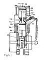
- a cylinder block 101 has each cylinder gas chamber 102, 103 on the upper and lower sides.
- the lower cylinder block is equipped with a lower piston 104 which can endure the explosion pressure and with a bias link pin 105 which can move the bias crank shaft 107 and cause rotative output.
- the upper piston 108 locates between the upper cylindric gas chamber 102 anf the lower piston. Using a piston link 117, the both parts connect each other. The phase relationship of both parts is synchronized, including the reach to the stop point and to the lower stop point at the same time. In Fig. 1, the exhaust opening 109 locates at the lower stop point in the lower gas chamber.
- the ignition plug 110 is equipped in the near of the top of the lower gas chamber. When we use jet oil inlet 110', only fresh airs can come into the pressure input gas chamber.
- the intake opening 111 is equipped in the near of the lower stop point in the upper gas chamber 102. It is equipped with a single way valve 112.
- the end of the gas transport opening of the combustion gas transport way 113 is equipped in the near of the lower stop point in the upper gas chamber. Its another end is equipped at the top point of the lower gas chamber and is located diagonally with the exhaust opening.
- the intake piece 114 is used for the control of the opening and closing of the gas transport way. This intake piece is controlled by the synchron mechanism, such as bias wheel on the flange shaft, synchron toothed belt and synchron bias gear.
- the synchron mechanism such as bias wheel on the flange shaft, synchron toothed belt and synchron bias gear.
- a gas pump chamber 102' is formed among the upper side of the upper piston 108 and the upper section of the upper gas chamber and the back side of the upper piston. Excepting the equipment of a gas opening 119 for the advance of the block, it can be also equipped with the additional inlet valve and outlet valve to form a pump for the pump using in the water, oil or gas, or for the movement of a pressurizing turbine.
- the ignition coil can ignite the combustion gas, when the lower piston 104 has reached the upper stop point.
- the combustion gas comes into the upper gas chamber 102 through the intake opening 111 and the single way intake valve 112 due to upward pump of the upper piston 108.
- the intake piece 114 is opened, the combustion gas comes into the lower gas chamber 103 through the combustion gas transport way 113 and pushes the exhaust gas through the exhaust opening to the open air.
- the ignition coil let the ignition plug 110 ignite and let the fresh combustion gas exploide.
- the upper piston 108 has the finished gas input and is prepared for the compression.
- Cooling opening 116 is used for the pump cooling fluids which can cool the oil seal 118 coupled with the upper and the lower piston link 117, the outer oil tank, the cooling fan or the liquid pump, the cooling liquid tank and the start motor...etc.
- the pump cooling fluids which can cool the oil seal 118 coupled with the upper and the lower piston link 117, the outer oil tank, the cooling fan or the liquid pump, the cooling liquid tank and the start motor...etc.
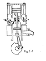
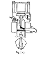
- Fig. 2-1, 2-2, 2-3 1 2-4 For its movement process, please refer to Fig. 2-1, 2-2, 2-3 1 2-4.
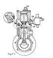
- the gas intake type connected from the upper gas chamber into the lower gas chamber with the above-said engine structure can be reached by the following method: As defined in Fig. 2-5, the upper piston link and the lower piston hollow link 201 have the hollow pipe, in which an intake opening 202 at the upper end and an exhaust opening 203 at the lower end. The time of the intake starting is decided by the position selection of the lower exhaust opening 203.
- the body structure is same as the diagram, but two sides of the upper piston 208 form two intake gas chambers separately with the upper gas chamber 204 and the upper section of the upper gas chamber 204', in which the upper gas chamber 204 is equipped with a single way intake opening valve and a single way exhaust opening valve 206 and a gas pump chamber 204' formed by the upper section of the upper gas chamber and the back side of the upper piston is equipped with a single way intake opening valve 205' and a single way exhaust opening valve 206'.
- Two intake opening valves 205 and 205' are connected separately with a carburetor.
- Two exhaust opening valves are connected separately with a pressure reservoir 207.
- This pressure reservoir is used for the acceptance of the compressed combustion gas pumped upward and downward by the upper piston for the increament of the gas intake density.
- the space between the output opening cf the pressure reservoir and the combustion chamber is used for the acceptance of the combustion gas controlled synchronously by the steam valve piece.
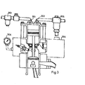
- 301 is the intake valve
- 302 is exhaust valve equipped at the upper side of the upper gas chamber or on the upper cover
- 303 is air filter connected to the front of the intake valve
- 304 is pressure reservoir connected with the exhaust valve
- 305 is the pressure reducing valve connected with the pressure reservoir
- 306 is pressure manometer.
- the above-said parts form an air compressor system for driving the air drive apparatus.
- 401 is an air drive turbine equipment, its air pump outlet 402 is coupled with the intake opening 403.
- the gas pump inlet 404 is connected with the carburetor.
- the upper section of the upper gas chamber and each side of the upper piston 406 form a gas pump chamber 405, the pump inlet 407 is equipped with the single way valve 408, the pump putlet is connected with the drive inlet 409 of the turbine equipemnt and its outlput goes through the outlet 410, so that the intake pressure increases during the running of the engine.
- Its function is same as the various used turbine pressurizing equipment. If we various used turbine pressurizing equipment. If we use the fluid to drive the turbine pressurizing equipment. the same function will be shown.
- the intake pressurizing of the above-said engine can be described in Fig. 4-1 and 4-2.
- the gas pump function is formed by the above formed double gas chambers 423 and 424. Adding the original piston 425 and the upper section of the upper gas chamber 426 to them, a gas pump is formed. The later can input the pressurizing combustion gas into the pressure reservoir 427.
- Each intake opening of the above-said pump chamber is equipped separately with the single way valves 428, 429 and 430 for the input of the combustion gas come from the carebutor.
- Each outlet is equipped also separately with the single way valve 431, 432 and 433 for the connection to the pressure reservoir 427.
- valve 434 between the pressure reservoir and the main pressurizing gas chamber 435 compressed twice.
- a intake door which can be adjusted is located between tne main pressurizing gas chamber 435 and the combustion ehamber. It can control the intake time.
- the air should be pre-compressed in order to increasement of the intake quantity and output power. Excepting the intake pre-corpression, the further process is same as which described in Fig. 1.
- Fig. 5 shows it is used as the liquid pump.
- the filter 501 is used for the filtration of the input fluids.
- the inlet valve 502 is connected with the filter and the inlet opening on the upper side of the pump chamber.
- the outlet valve 503 is connected with the parts between the pump chamber and the fluid load.
- the pressurizing valve 504 is connected with the parts between the input side and the output side and forms a liquid pump function with the direct drive.
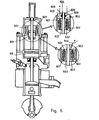
- a permanent magnetic pole 601 is equipped on the upper piston 108 in Fig. 1; o- a magnetic pole 630 is magnetized by the current runs through the coil 602 and is connected with the .power supply using the soft conducting wire 604; or the magnetization produced by the conduction of the current using a set of cabon brush 605 and conducting rod 606.
- the inductive voltage is generated dur to the change of magnetizing quantity between the magnetizing pole and the electric coil 607 and thus it can supply the electrical energy. Therefore, it bacomes a linear drive electric generating equipment.
- the position of the above-said permanent magnetic pole and the electric generating winding can be reserved as shown in Fig. 6-1.
- the magnetic field is formed by the permanent magnet 601' or the ring coil 602', in which the movable parts are formed by the electric generating winding 607' and its electric energy is transmitted by the carbon brush 605' and the conducting rod 606' or the soft conducting wire 604'.
- the abovementioned electric generating equipment can be equipped on the upper side of the upper piston and is moved by a rod extended from the upper piston as shown in Figure 7, in order to avoidance of the electric fenerating volume limited by the space of the pressurizing cylinder an in order to getting better power match of the engine power and the electric generating power; or in order to keeping the pump drive function of the piston on the pressurizing gas chamber.
- the upper link 701 is connected with the upper side of the upper piston 108.
- the gas seal cover 702 is used for the sealing of the upper gas chamber cover and the upper link 701.
- No. 701 is magnetizing pole; 704 is electric generating winding; 705 is magnetic circuit iron core.
- the selection of the structure design for the electric generation can be done as the abovementioned one, thus the magnetizing pole and the electric generating winding are equipped inversely and the electric energy is transmitted to the middle moving parts using the conducting rod and the carbon brush or the soft conducting wire.
- the diameter and the relative dimensions can be selected for the power match in the electric generating equipment.
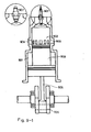
- the abovementioned lineal drive electric generating equipment can be used for the traditional engine (See Fig. 8). Its structure character is same as the abovementioned example.
- the transmission rod 801 is equipped on the piston and the pierce through the cylinder cover 802.
- the gas seal cover 803 is used for the sealing of the lineal drive electric generating equipment coupled parts between the transmission rod 801 and the cylinder cover 802 and can move back and forth dependent on the moving of the piston, so that the electric energy can be generated.
- the outer ring electric equipment has fixed structure and the middle electric equipment is linked with the piston, it can be done by the inverse direction, i.e. the outer ring electric equipment is dynamic acceptance piston and moves forth and back, the middle electric equipment is atastic one and acts as the input or the output type of the electric energy for the outer cycle structure.
- the work is performed by the abovementioned method, i.e. by the soft conducting wires or the conducting rods or the carbon brushes.
- This engine uses practically the diameters of the upper gas chamber and its upper piston and the lower gas chamber and its lower piston and can select the diameter according to the requirement in order to arrangement of the size of the pressure input gas chamber and explosion gas chamber for the used selection. For example, we can select the larger pressure input gas chamber for the lower density air in the high open air.
- the structure types of the separate gas chamber engine with the different cylinder diameters have the separate gas chambers with a larger and a small diameters respectively in the engine body. Its inner body has also a piston with the different diameter.
- This piston is connected separately with two gas chambers coupled respectively with two different diameters, in which a set one is explosion gas chamber 902 (the upper gas chamber in the diagram) and the another set is the pressure input gas chamber 901 (ring type lower gas chamber in the diagram).
- the piston 903 has a transverse lever link 904 for the connection of the shaking rod 955 and for the driving crank shaft 906.
- a ignition plug 907 or a fuel nozzole 907' and a single way intake door 908 connected with the pressure reservoir are equipped in the near of the upper stop point of the combustion gas chamber.
- a exhaust opening 909 is equipped in the near of the lower stop of the explosion gas chamber 902.
- a single way intake door 910 and a single way exhaust opening 911 connected with the pressure reservoir 912 are eouipped in the near of the upper stop point gas chamber. After the engine has started, the combustion gases with the high pressure are stored in the pressure reservoir 912 for each work cycle due to the pressure input volume is larger than the explosion gas chamber. During the intake travel, the intake door is opened and the fresh airs come into the combustion chamber.
- the lubricating oil can be distributed by the pump leaf blade equipped on the crank shaft to inside of the piston and then penestrated to the friction surfaces.
- the engine housing 1001 has gas chambers with a large and a small diameters respectively, in which the upper gas chamber is two travel standard pressure input explosion gas chamber 1002 and the lower ring gas chamber with the larger diameter is pump chamber 1003 used for the fluid pump.
- the upper gas chamber is two travel standard pressure input explosion gas chamber 1002
- the lower ring gas chamber with the larger diameter is pump chamber 1003 used for the fluid pump.
- a inlet of a single way valve 1004 and a outlet of the another single way valve 1005 are equipped. They can generate the gas pump function in the engine drive. Because this engine has a larger volume of the lower piston, the pressure generated by equipment.
- the above-said linear drive electric generating equipment and the above-said direct drive fluid pump can be used for the traditional engine (See Fig. 8). Its structure feature is same as the above-said exanple.
- the transmission rod 801 is equipped on the piston and the pierce through the cylinder cover 802.
- the gas seal cover 803 is used for the sealing of the linear drive electric generating equipment coupled parts between the transmission rod 801 and the cylinder cover 802 and can move back and forth dependent on the moving of the piston, so that the electric energy can be generated; or as shown in Fig.
- the upper piston 804 drived back and forth by the transmission rod 801;
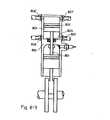
- the cylinder set 805 coupled with the piston is installed in the upper side of the engine and the single way input valve 806 and single way output valve 807 whcih generate the pump motive effect are installed in the upper side or lower side of the cylinder set 805; or furthermore as shown in Fig.
- FIG. 8-2 the upper side of the cylinder set 805 is shown the seal situation and the piston 804 is shown two ways pump motion and the two ends of the gas chamber of the upper gas cylinder set install single way input valves 806 and 806' which connected each other in parallel, and the single way output valves 807 and 807' to generate the two ways pump motion drived forth and back by the piston 804;
- the further feature of this two ways pump motion structure is shown in Fig. 8-3, the upper and lower input and output valves are connected respectively to the pump motive fluids to form two independent pump system which don't transmit each other.
- the outer ring electric equipment has fixed structure and the middle elctric equipment is lined with the piston, it can be done by the inverse direction, i.e. the outer ring electric equipment is dynamic acceptance piston and moves forth and back, the middle electric equipment is stastic one and acts as the input or the output type of the electric energy for the outer cycle structure.
- the work is performed by the above-said method, i.e. by the soft conducting wires or the conducting rods or the carbon brushes.
- This engine uses practically the diameters of the upper gas chamber and its upper piston and the lower gas chamber and its lower piston and can select the diameter according to the requirement in order to arrangement of the size of the pressure input gas chamber and explosion gas chamber for the used selection. For example, we can select the larger pressure input gas chamber for the lower density air in the high open air.
- the structure types of the separate gas chamber engine with the different cylinder diameters have the separate gas chambers with a larger and a small diameters respectively in the engine body. Its inner body has also a piston with the different diameter.
- This piston is connected separately with two gas chambers coupled respectively with two different diameters, in which one set is explosion gas chamber 902 (the upper gas chamber and having smaller volume of gas chamber in the diagram) and the another set is the pressure input gas chamber 901 (the ring type lower gas chamber and having larger volume of gas chamber in the diagram).
- the piston 903 has a transverse lever link 904 for the connection of the shaking rod 955 and for the driving crank shaft 906.
- a ignition plug 907 or a fuel nozzle 907' and a single way intake door 908 connected with the pressure reservoir are equipped in the near of the upper stop point of the combustion gas chamber.
- a exhaust opening 909 is equipped in the near of the lower stop point of the explosion gas chamber 902.
- a single way intake door 910 and a single way exhaust opening 911 connected with the pressure reservoir 912 are equipped in the near of the upper stop point gas chamber. After the engine has started, the combustion gases with the high pressure are stored in the pressure reservoir 912 for each work cycle due to the pressure input volume is larger than the explosion gas chamber. During the intake travel, the intake door is opened and the fresh airs come into the combustion chamber.
- the lubricating oil can be distributed by the pump leaf blade equipped on the crank shaft to inside of the piston and then pentrated to the friction surfaces.
- the engine housing 1001 has gas chamber with a larger and a small diameters respectively, in which the upper gas chamber is two travel standard pressure input explosion gas chamber 1002 and the lower ring gas chamber with the larger diameter is pump chamber 1003 used for the fluid pump.
- the upper gas chamber is two travel standard pressure input explosion gas chamber 1002
- the lower ring gas chamber with the larger diameter is pump chamber 1003 used for the fluid pump.
- an inlet of a single way valve 1004 and an oulet of the another single way valve 1005 are equipeed. They can generate the gas pump function in the engine drive. Because the engine has a larger volume of the lower piston, the pressure generated by the crank shaft case used for the intake pump of the two travel engine during the running travel is larger than the traditional one and is more adventage for the intake.
- Fig. 11 and 11-1 show the application example of the equipment in the four travel engine. Its structure feature is same as which shown in the two travel one.
- this case is a improved application structure, please give us an approval.
Landscapes
- Engineering & Computer Science (AREA)
- Chemical & Material Sciences (AREA)
- Combustion & Propulsion (AREA)
- Mechanical Engineering (AREA)
- General Engineering & Computer Science (AREA)
- Combustion Methods Of Internal-Combustion Engines (AREA)
- Valve Device For Special Equipments (AREA)
- Output Control And Ontrol Of Special Type Engine (AREA)
- Compressors, Vaccum Pumps And Other Relevant Systems (AREA)
Priority Applications (1)
| Application Number | Priority Date | Filing Date | Title |
|---|---|---|---|
| AT86308255T ATE86004T1 (de) | 1985-10-23 | 1986-10-23 | Zweitakt - brennkraftmaschine. |
Applications Claiming Priority (4)
| Application Number | Priority Date | Filing Date | Title |
|---|---|---|---|
| GB8526129 | 1985-10-23 | ||
| GB858526129A GB8526129D0 (en) | 1985-10-23 | 1985-10-23 | Back & forth motion type of internal engine |
| GB8527317 | 1985-11-06 | ||
| GB858527317A GB8527317D0 (en) | 1985-10-23 | 1985-11-06 | Back & forth motion of internal engine |
Related Child Applications (1)
| Application Number | Title | Priority Date | Filing Date |
|---|---|---|---|
| EP92113454.0 Division-Into | 1992-08-07 |
Publications (2)
| Publication Number | Publication Date |
|---|---|
| EP0223435A1 true EP0223435A1 (de) | 1987-05-27 |
| EP0223435B1 EP0223435B1 (de) | 1993-02-24 |
Family
ID=26289920
Family Applications (2)
| Application Number | Title | Priority Date | Filing Date |
|---|---|---|---|
| EP86308255A Expired - Lifetime EP0223435B1 (de) | 1985-10-23 | 1986-10-23 | Zweitakt - Brennkraftmaschine |
| EP19920113454 Withdrawn EP0513868A3 (en) | 1985-10-23 | 1986-10-23 | A reciprocating internal combination engine including a separate gas chamber |
Family Applications After (1)
| Application Number | Title | Priority Date | Filing Date |
|---|---|---|---|
| EP19920113454 Withdrawn EP0513868A3 (en) | 1985-10-23 | 1986-10-23 | A reciprocating internal combination engine including a separate gas chamber |
Country Status (7)
| Country | Link |
|---|---|
| EP (2) | EP0223435B1 (de) |
| AT (1) | ATE86004T1 (de) |
| AU (1) | AU606316B2 (de) |
| CA (1) | CA1333869C (de) |
| DE (1) | DE3687821T2 (de) |
| ES (1) | ES2037662T3 (de) |
| IN (1) | IN172321B (de) |
Cited By (3)
| Publication number | Priority date | Publication date | Assignee | Title |
|---|---|---|---|---|
| EP0514982A1 (de) * | 1991-05-20 | 1992-11-25 | PIAGGIO VEICOLI EUROPEI S.p.A. | Brennkraftmaschine mit einem getrennten Gasraum für die Brennstoffeinspritzung |
| US5713521A (en) * | 1995-06-26 | 1998-02-03 | Scheffel; Bernd W. | Apparatus for intermittently atomizing a fluid |
| CN114382589A (zh) * | 2021-12-23 | 2022-04-22 | 李国忠 | 一种超高压进气富氧燃烧二冲程内燃机 |
Citations (9)
| Publication number | Priority date | Publication date | Assignee | Title |
|---|---|---|---|---|
| DE223985C (de) * | ||||
| GB193651A (en) * | 1922-02-08 | 1923-03-01 | Guy Ernest Sidney | Improvements in internal combustion engines |
| DE504514C (de) * | 1927-07-23 | 1930-08-08 | Bernhard Plage | Zweitaktbrennkraftmaschine |
| GB396369A (en) * | 1930-10-30 | 1933-08-03 | Sven Lindequist | Improvements in and relating to internal combustion engines |
| GB820311A (en) * | 1954-08-31 | 1959-09-16 | Ake Elvir Anderberg | Improvements in and relating to internal combustion engines and apparatus incorporating the same for the production of electrical energy |
| DE1214474B (de) * | 1961-06-15 | 1966-04-14 | Maschf Augsburg Nuernberg Ag | Zweitakt-Brennkraftmaschine mit Abgasturbo-aufladung |
| GB1137087A (en) * | 1965-05-04 | 1968-12-18 | Maschf Augsburg Nuernberg Ag | Improvements in or relating to driving radial-flow compressors |
| DE1526366A1 (de) * | 1966-07-07 | 1970-10-29 | Dietmar Wagner | Kolbenmaschine zur Verdraengung und/oder zur Verdichtung eines Arbeitsmediums |
| DE2901815A1 (de) * | 1979-01-18 | 1980-07-31 | Fichtel & Sachs Ag | Viertakt-brennkraftmaschine mit stufenkolben |
Family Cites Families (7)
| Publication number | Priority date | Publication date | Assignee | Title |
|---|---|---|---|---|
| FR569117A (fr) * | 1922-07-29 | 1924-04-07 | Pompe automatique à simple ou à double effet | |
| FR644843A (fr) * | 1927-11-10 | 1928-10-15 | Perfectionnements aux moteurs à combustion interne | |
| FR2386684A1 (fr) * | 1977-04-04 | 1978-11-03 | Chrysler France | Moteur deux temps a balayage equicourant |
| DE2743780A1 (de) * | 1977-09-29 | 1979-04-12 | Fichtel & Sachs Ag | Einzylinder-hubkolben-brennkraftmaschine |
| DE2847731A1 (de) * | 1978-11-03 | 1980-05-14 | Fichtel & Sachs Ag | Einzylinder-hubkolben-brennkraftmaschine |
| DE3201875A1 (de) * | 1982-01-22 | 1983-08-04 | Wolfgang Prof. Dipl.-Ing. 8201 Hochstätt Zimmermann | Druch einen verbrennungsmotor angetriebene kolbenpumpe fuer arbeitsfluide |
| JPS58143121A (ja) * | 1982-02-19 | 1983-08-25 | Kawasaki Heavy Ind Ltd | 2サイクルエンジン |
-
1986
- 1986-10-21 CA CA000521022A patent/CA1333869C/en not_active Expired - Fee Related
- 1986-10-22 IN IN934DE1986 patent/IN172321B/en unknown
- 1986-10-23 AT AT86308255T patent/ATE86004T1/de not_active IP Right Cessation
- 1986-10-23 DE DE8686308255T patent/DE3687821T2/de not_active Expired - Fee Related
- 1986-10-23 ES ES198686308255T patent/ES2037662T3/es not_active Expired - Lifetime
- 1986-10-23 EP EP86308255A patent/EP0223435B1/de not_active Expired - Lifetime
- 1986-10-23 EP EP19920113454 patent/EP0513868A3/en not_active Withdrawn
- 1986-10-23 AU AU64317/86A patent/AU606316B2/en not_active Ceased
Patent Citations (9)
| Publication number | Priority date | Publication date | Assignee | Title |
|---|---|---|---|---|
| DE223985C (de) * | ||||
| GB193651A (en) * | 1922-02-08 | 1923-03-01 | Guy Ernest Sidney | Improvements in internal combustion engines |
| DE504514C (de) * | 1927-07-23 | 1930-08-08 | Bernhard Plage | Zweitaktbrennkraftmaschine |
| GB396369A (en) * | 1930-10-30 | 1933-08-03 | Sven Lindequist | Improvements in and relating to internal combustion engines |
| GB820311A (en) * | 1954-08-31 | 1959-09-16 | Ake Elvir Anderberg | Improvements in and relating to internal combustion engines and apparatus incorporating the same for the production of electrical energy |
| DE1214474B (de) * | 1961-06-15 | 1966-04-14 | Maschf Augsburg Nuernberg Ag | Zweitakt-Brennkraftmaschine mit Abgasturbo-aufladung |
| GB1137087A (en) * | 1965-05-04 | 1968-12-18 | Maschf Augsburg Nuernberg Ag | Improvements in or relating to driving radial-flow compressors |
| DE1526366A1 (de) * | 1966-07-07 | 1970-10-29 | Dietmar Wagner | Kolbenmaschine zur Verdraengung und/oder zur Verdichtung eines Arbeitsmediums |
| DE2901815A1 (de) * | 1979-01-18 | 1980-07-31 | Fichtel & Sachs Ag | Viertakt-brennkraftmaschine mit stufenkolben |
Cited By (5)
| Publication number | Priority date | Publication date | Assignee | Title |
|---|---|---|---|---|
| EP0514982A1 (de) * | 1991-05-20 | 1992-11-25 | PIAGGIO VEICOLI EUROPEI S.p.A. | Brennkraftmaschine mit einem getrennten Gasraum für die Brennstoffeinspritzung |
| US5271372A (en) * | 1991-05-20 | 1993-12-21 | Piaggio Veicoli Europei S.P.A. | Cylinder head for internal combustion engines, with a device for pneumatically assisted direct fuel injection |
| US5713521A (en) * | 1995-06-26 | 1998-02-03 | Scheffel; Bernd W. | Apparatus for intermittently atomizing a fluid |
| CN114382589A (zh) * | 2021-12-23 | 2022-04-22 | 李国忠 | 一种超高压进气富氧燃烧二冲程内燃机 |
| CN114382589B (zh) * | 2021-12-23 | 2023-03-07 | 李国忠 | 一种超高压进气富氧燃烧二冲程内燃机 |
Also Published As
| Publication number | Publication date |
|---|---|
| ES2037662T3 (es) | 1993-07-01 |
| EP0513868A3 (en) | 1993-06-16 |
| IN172321B (de) | 1993-06-12 |
| AU606316B2 (en) | 1991-02-07 |
| DE3687821T2 (de) | 1993-06-17 |
| ATE86004T1 (de) | 1993-03-15 |
| EP0513868A2 (de) | 1992-11-19 |
| CA1333869C (en) | 1995-01-10 |
| EP0223435B1 (de) | 1993-02-24 |
| DE3687821D1 (de) | 1993-04-01 |
| AU6431786A (en) | 1987-04-30 |
Similar Documents
| Publication | Publication Date | Title |
|---|---|---|
| CA2190393C (en) | Linear electrical energy generator | |
| US7383796B2 (en) | Internal combustion engine | |
| CN102770637B (zh) | 燃烧管理系统 | |
| US4924956A (en) | Free-piston engine without compressor | |
| JP2001522427A (ja) | 内燃機関 | |
| US6626650B1 (en) | Cyclically operated fluid displacement machine | |
| CN111535924A (zh) | 一种点燃式二冲程航空重油活塞发动机 | |
| KR960008774B1 (ko) | 동력집합체(Power aggregate) | |
| US4841921A (en) | Two-cycle, dual piston internal combustion engine with air turbine driven fuel/air mixture supply | |
| CN109339944B (zh) | 一种微型自由活塞发电机 | |
| US4785770A (en) | Coaxial pump and motor cylinder engine | |
| CA1333869C (en) | Reciprocating internal combustion engine including a separate gas chamber | |
| US4858571A (en) | Liquid pump driven by a two-cycle, dual piston internal combustion engine | |
| US4838216A (en) | Four cycle, dual piston internal combustion engine and pump | |
| US4745886A (en) | Back and forth motion type of the internal engine with the separate gas chamber and its application equipment | |
| US4836150A (en) | Combined fluid pump and two-cycle, internal combustion engine | |
| US11846230B2 (en) | Adaptive linear linked piston electric power generator | |
| US2382598A (en) | Compressor | |
| RU2176025C1 (ru) | Тепловая электрогенерирующая машина | |
| WO2003069142A1 (en) | Free piston internal combustion engine | |
| JPS6312828A (ja) | 分離空気室を持つた往復式内燃エンジン及び応用装置 | |
| RU2152523C1 (ru) | Двигатель внутреннего сгорания | |
| US6244826B1 (en) | Gaseous piston method for suction and compression in closed chamber gas equipments | |
| WO1990012952A1 (en) | Two stroke internal combustion engine | |
| GB2085963A (en) | Crankcase compression four stroke engine with piston controlled parts |
Legal Events
| Date | Code | Title | Description |
|---|---|---|---|
| PUAI | Public reference made under article 153(3) epc to a published international application that has entered the european phase |
Free format text: ORIGINAL CODE: 0009012 |
|
| AK | Designated contracting states |
Kind code of ref document: A1 Designated state(s): AT BE CH DE ES FR GB GR IT LI LU NL SE |
|
| 17P | Request for examination filed |
Effective date: 19871119 |
|
| 17Q | First examination report despatched |
Effective date: 19880222 |
|
| GRAA | (expected) grant |
Free format text: ORIGINAL CODE: 0009210 |
|
| AK | Designated contracting states |
Kind code of ref document: B1 Designated state(s): AT BE CH DE ES FR GB GR IT LI LU NL SE |
|
| PG25 | Lapsed in a contracting state [announced via postgrant information from national office to epo] |
Ref country code: GR Free format text: LAPSE BECAUSE OF FAILURE TO SUBMIT A TRANSLATION OF THE DESCRIPTION OR TO PAY THE FEE WITHIN THE PRESCRIBED TIME-LIMIT Effective date: 19930224 Ref country code: BE Effective date: 19930224 Ref country code: AT Effective date: 19930224 |
|
| REF | Corresponds to: |
Ref document number: 86004 Country of ref document: AT Date of ref document: 19930315 Kind code of ref document: T |
|
| XX | Miscellaneous (additional remarks) |
Free format text: TEILANMELDUNG 92113454.0 EINGEREICHT AM 23/10/86. |
|
| ET | Fr: translation filed | ||
| REF | Corresponds to: |
Ref document number: 3687821 Country of ref document: DE Date of ref document: 19930401 |
|
| ITF | It: translation for a ep patent filed | ||
| REG | Reference to a national code |
Ref country code: ES Ref legal event code: FG2A Ref document number: 2037662 Country of ref document: ES Kind code of ref document: T3 |
|
| PGFP | Annual fee paid to national office [announced via postgrant information from national office to epo] |
Ref country code: ES Payment date: 19931029 Year of fee payment: 8 |
|
| ITTA | It: last paid annual fee | ||
| PG25 | Lapsed in a contracting state [announced via postgrant information from national office to epo] |
Ref country code: LU Free format text: LAPSE BECAUSE OF NON-PAYMENT OF DUE FEES Effective date: 19931031 |
|
| PGFP | Annual fee paid to national office [announced via postgrant information from national office to epo] |
Ref country code: NL Payment date: 19931031 Year of fee payment: 8 |
|
| PLBE | No opposition filed within time limit |
Free format text: ORIGINAL CODE: 0009261 |
|
| STAA | Information on the status of an ep patent application or granted ep patent |
Free format text: STATUS: NO OPPOSITION FILED WITHIN TIME LIMIT |
|
| 26N | No opposition filed | ||
| PG25 | Lapsed in a contracting state [announced via postgrant information from national office to epo] |
Ref country code: ES Free format text: LAPSE BECAUSE OF EXPIRATION OF PROTECTION Effective date: 19941024 |
|
| EAL | Se: european patent in force in sweden |
Ref document number: 86308255.8 |
|
| PG25 | Lapsed in a contracting state [announced via postgrant information from national office to epo] |
Ref country code: NL Effective date: 19950501 |
|
| NLV4 | Nl: lapsed or anulled due to non-payment of the annual fee | ||
| PGFP | Annual fee paid to national office [announced via postgrant information from national office to epo] |
Ref country code: GB Payment date: 19961023 Year of fee payment: 11 |
|
| PGFP | Annual fee paid to national office [announced via postgrant information from national office to epo] |
Ref country code: SE Payment date: 19961030 Year of fee payment: 11 |
|
| PGFP | Annual fee paid to national office [announced via postgrant information from national office to epo] |
Ref country code: CH Payment date: 19961111 Year of fee payment: 11 |
|
| PG25 | Lapsed in a contracting state [announced via postgrant information from national office to epo] |
Ref country code: GB Free format text: LAPSE BECAUSE OF NON-PAYMENT OF DUE FEES Effective date: 19971023 |
|
| PG25 | Lapsed in a contracting state [announced via postgrant information from national office to epo] |
Ref country code: SE Free format text: LAPSE BECAUSE OF NON-PAYMENT OF DUE FEES Effective date: 19971024 |
|
| PG25 | Lapsed in a contracting state [announced via postgrant information from national office to epo] |
Ref country code: LI Free format text: LAPSE BECAUSE OF NON-PAYMENT OF DUE FEES Effective date: 19971031 Ref country code: CH Free format text: LAPSE BECAUSE OF NON-PAYMENT OF DUE FEES Effective date: 19971031 |
|
| PGFP | Annual fee paid to national office [announced via postgrant information from national office to epo] |
Ref country code: DE Payment date: 19980427 Year of fee payment: 12 |
|
| PGFP | Annual fee paid to national office [announced via postgrant information from national office to epo] |
Ref country code: FR Payment date: 19980430 Year of fee payment: 12 |
|
| GBPC | Gb: european patent ceased through non-payment of renewal fee |
Effective date: 19971023 |
|
| REG | Reference to a national code |
Ref country code: CH Ref legal event code: PL |
|
| EUG | Se: european patent has lapsed |
Ref document number: 86308255.8 |
|
| PG25 | Lapsed in a contracting state [announced via postgrant information from national office to epo] |
Ref country code: FR Free format text: LAPSE BECAUSE OF NON-PAYMENT OF DUE FEES Effective date: 19990630 |
|
| REG | Reference to a national code |
Ref country code: ES Ref legal event code: FD2A Effective date: 19990601 |
|
| REG | Reference to a national code |
Ref country code: FR Ref legal event code: ST |
|
| PG25 | Lapsed in a contracting state [announced via postgrant information from national office to epo] |
Ref country code: DE Free format text: LAPSE BECAUSE OF NON-PAYMENT OF DUE FEES Effective date: 19990803 |
|
| PG25 | Lapsed in a contracting state [announced via postgrant information from national office to epo] |
Ref country code: IT Free format text: LAPSE BECAUSE OF NON-PAYMENT OF DUE FEES;WARNING: LAPSES OF ITALIAN PATENTS WITH EFFECTIVE DATE BEFORE 2007 MAY HAVE OCCURRED AT ANY TIME BEFORE 2007. THE CORRECT EFFECTIVE DATE MAY BE DIFFERENT FROM THE ONE RECORDED. Effective date: 20051023 |