EP0223461A1 - Logique de décision testable pour interface de puissance - Google Patents
Logique de décision testable pour interface de puissance Download PDFInfo
- Publication number
- EP0223461A1 EP0223461A1 EP86308456A EP86308456A EP0223461A1 EP 0223461 A1 EP0223461 A1 EP 0223461A1 EP 86308456 A EP86308456 A EP 86308456A EP 86308456 A EP86308456 A EP 86308456A EP 0223461 A1 EP0223461 A1 EP 0223461A1
- Authority
- EP
- European Patent Office
- Prior art keywords
- switches
- test
- load
- switch
- current
- Prior art date
- Legal status (The legal status is an assumption and is not a legal conclusion. Google has not performed a legal analysis and makes no representation as to the accuracy of the status listed.)
- Withdrawn
Links
Images
Classifications
-
- G—PHYSICS
- G05—CONTROLLING; REGULATING
- G05B—CONTROL OR REGULATING SYSTEMS IN GENERAL; FUNCTIONAL ELEMENTS OF SUCH SYSTEMS; MONITORING OR TESTING ARRANGEMENTS FOR SUCH SYSTEMS OR ELEMENTS
- G05B9/00—Safety arrangements
- G05B9/02—Safety arrangements electric
- G05B9/03—Safety arrangements electric with multiple-channel loop, i.e. redundant control systems
-
- G—PHYSICS
- G21—NUCLEAR PHYSICS; NUCLEAR ENGINEERING
- G21D—NUCLEAR POWER PLANT
- G21D3/00—Control of nuclear power plant
- G21D3/04—Safety arrangements
-
- Y—GENERAL TAGGING OF NEW TECHNOLOGICAL DEVELOPMENTS; GENERAL TAGGING OF CROSS-SECTIONAL TECHNOLOGIES SPANNING OVER SEVERAL SECTIONS OF THE IPC; TECHNICAL SUBJECTS COVERED BY FORMER USPC CROSS-REFERENCE ART COLLECTIONS [XRACs] AND DIGESTS
- Y02—TECHNOLOGIES OR APPLICATIONS FOR MITIGATION OR ADAPTATION AGAINST CLIMATE CHANGE
- Y02E—REDUCTION OF GREENHOUSE GAS [GHG] EMISSIONS, RELATED TO ENERGY GENERATION, TRANSMISSION OR DISTRIBUTION
- Y02E30/00—Energy generation of nuclear origin
- Y02E30/30—Nuclear fission reactors
Definitions
- This invention relates generally to protection systems for complex processes, such as nuclear power plants, in which voted logic power circuits are used to actuate protective equipment. More particularly, it is directed apparatus and method for on-line testing of such circuits.
- Protection systems for complex processes monitor selected process parameters, such as temperatures, pressures and flows, and the status of various components such as whether a valve is open or closed or whether a pump is on or off, and provide automatic responses to measured values of the parameters and to detected status states of the components which require positive intervention to prevent, or to alleviate the effects of, abnormal process conditions.
- High reliability is an essential requirement for such a system.
- a nuclear power plant is one example of a complex process in which such a protection system is employed.
- the protection system in a nuclear power plant performs a plurality of functions. It can shutdown, or trip, the reactor if conditions warrant, or it can perform a number of engineered safeguard functions, such as opening or closing valves and turning on or off pumps or other components.
- the trip function involves deenergizing electromechanical jacks which normally hold control rods in a position withdrawn from the reactor core so that the rods reenter the core and cause it to go subcritical.
- the engineered safeguard functions may involve either deenergizing a load device which is normally energized or energizing a device which is normally deenergized.
- each sensor is compared with a setpoint value to generate a digital signal which is referred to as a partial actuation signal, since an indication from more than one sensor is required to actuate the safety component.
- the four partial actuation signals for each parameter or status condition are all fed to each of two identical, electrically isolated logic trains. Typically, this is accomplished by applying each partial actuation signal to the coil of a relay having one set of contacts in each logic train. Each logic train independently votes the partial actuation signals, such as two out of four, and generates an actuation signal.
- the two independently generated actuation signals are then applied to a power interface circuit which requires the presence of both actuation signals to actuate the load device, either a normally energized or normally deenergized component, to initiate the engineered safeguard function.
- a power interface circuit which requires the presence of both actuation signals to actuate the load device, either a normally energized or normally deenergized component, to initiate the engineered safeguard function.
- a known arrangement proposes the use of a "two out of three" voting power interface instead of the common two out of two arrangement.
- the interface described there utilizes serially connected groups of parallel connected switches with large resistors shunting the switches to provide a leakage path for measuring current through the interface to determine switch condition.
- This invention provides a novel apparatus and a method for automatically testing voted logic power interface circuits, at the same time enabling making such tests while maintaining the protection function of the protection system.
- the invention in its broad form resides in a testable power interface circuit for selectively connecting a power source to a load which is used with a protection system of a complex, process control system, said control system comprising: a load; an electric power source; three pairs of switches arranged in three groups with said groups of switches connected in parallel with each other and in series with the load and the electric power source, each said group of switches including a different combination of two switches connected in series, each from a different one of said pairs of switches; separate means for applying an actuating signal to each pair of switches, such that said load is actuated when at least any two out of said three pairs of switches are actuated; a test unit for selectively generating a test signal for each switch; characterized by means for applying said test signal to each switch without removing said actuation signal such that said load is responsive to the actuation signals even while test signals are applied to said switches; and current measuring means for measuring the current flowing through each said group of switches and for applying said measurements to the test unit, said test unit including means for generating selected
- a preferred embodiment described herein uses n out of m voted power interface.
- a protection system such as for example would be used with a nuclear reactor
- practical values for n and m are two and three respectively, so that confirmation by two out of three independent sources is required to initiate action.
- Such a "two out of three" interface includes three pairs of switches arranged in three parallel connected groups of switches. Each group includes a different combination of two switches connected in series, each from a different one of the three pairs of switches.
- the three parallel connected groups of switches are connected in series with a load and an electric power source. Each pair of switches is actuated by a separate actuation signal such that two out of three of the pairs of switches must be actuated to actuate the load.
- the switches are normally closed and are actuated to the open position in the case of a normally energized load while normally open switches are used with normally deenergized load.
- the power interface circuit is tested by a test generator which generates a test signal for each switch in the power interface.
- a gate associated with each switch actuates the switch in response to either the actuation signal associated with that switch or the test signal.
- Current detectors detect the current flowing through the switches in each group of serially connected switches.
- the test generator generates patterns of test signals which actuate selected switches and compares the currents detected by the current detectors with expected values for each pattern. Deviations from the expected pattern indicate malfunctions in the system. For normally energized loads, the protection function remains operational while the power interface is being tested.
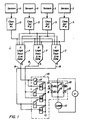
- the exemplary system 1 employs four redundant sets of sensors 3 to monitor selected plant parameters such as pressure, temperature, flow, radiation level, et cetera, and/or the status of various components, such as whether a valve is open or closed or whether a pump is running or not. Where such a system is used for a particular safeguard function, the sensors 3 may monitor only one or a plurality of plant parameters or conditions.
- the signals generated by each set of sensors 3 are applied to separate channel sets 5, numbered 1 through 4 in Figure 1, where the detected values of the sensor signals are analyzed for an indication of an abnormal condition by comparing them with selected setpoint values.
- the values of measured parameters are used to calculate other parameters which are then compared with limiting values for an indication of an abnormal condition as is well-known in the field of control system engineering.
- Each channel set generates a digital output signal which indicates whether or not the sensors in that channel set are sensing conditions which warrant actuation of the associated safeguard function. Since.confirmation by more than one channel set is required to initiate the safeguard function, the digital signals are referred to as "partial actuation signals".
- the partial actuation signals from each of the channel sets 5 are each applied to three independent logic trains 7 labeled A, B and C in Figure 1.
- they are electrically isolated from one another such as by applying each of them to the coil of a separate relay in each logic train as is now common practice.
- the coil to contact separation of these relays provides the electrical isolation between the actuation signals and between the logic trains. Isolation could also be provided for instance, by optical isolators where solid state switches are used in place of relays.
- the logic trains 7 independently vote the partial trip signals received from the four channel sets 5 and generate an actuation signal a, b or c on their associated output lines 9 when the prescribed number of partial trip signals is detected.
- two out of four voting logic is employed by these logic trains. That is, two out of the four channel sets must be generating a partial actuation signal in order for the logic train to generate an actuation signal.
- Such a scheme allows for failures which preclude the generation of a partial actuation signal by two of the channel sets, while reducing the likelihood of a spurious trip which could occur if only one partial trip signal was required to generate an actuation signal.
- all four channel sets would generate partial actuation signals upon the occurrence of the abnormal condition, and all three logic trains 7 would generate an actuation signal.
- voting strategies other than two out of four could be employed by the logic trains 7.
- the actuation signals on the leads 9 are utilized to control the energization of a load device 11 by a voltage source V through a power interface identified generally in Figure 1 by the reference character 13.
- the load device 11 may be any type of electrically operated device which effects an automatic response to the detection of the associated abnormal condition.
- a device could be for example, a pump, an electrically controlled valve, a heater, a circuit breaker or any motor driven device.
- the load device would be a normally energized device, but as will be seen, the invention can also be used with normally deenergized load devices also.
- the power interface 13 includes a network of switches connected in series with the load device 11 across the voltage source V.
- the switches are the normally closed contacts 15 of relays A, (A), B, (B), C and (C).
- the coils 17 of two relays are connected to the output line 9 from each logic train 7.
- the contacts of these coils are connected in three groups 19 of two contacts each with the two contacts in each group connected in series and the groups connected in parallel.
- the two contacts in each group are associated with relays energized by different logic trains.
- the first group includes the break contacts of relays A and B; the second, contacts of relays (A) and (C); and the third contacts of relays (B) and C.
- the invention encompasses a unique arrangement for testing power interfaces such as that shown in Figure 1.
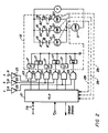
- Figure 2 illustrates an arrangement for testing the power interface circuit 13 for a normally energized load 11 that forms part of the protection system 1 shown in Figure 1.
- the arrangement includes a test unit or generator 21 in the form, for example, of a microprocessor.
- the microprocessor 21 generates a separate test signal for each of the relays of power interface circuit 13. Each test signal is applied to the coil 17 of the associated relay through a NAND circuit 23.
- a logic level actuation signal a, b or c generated on a line 9 by one of the three logic trains 7 (see Figure 1) is applied as a second input to each NAND circuit 23 through an inverter 25.
- the microprocessor 21 When not in the test mode, the microprocessor 21 generates a high level signal which gates any actuation signal generated by a logic train to the appropriate relay coil.
- the microprocessor During testing, which may be initiated automatically through application of a test initiate signal TI to the microprocessor 21, or manually through actuation of the test button TB, the microprocessor sequentially generates patterns of low level signals which result in energization of the associated relay coils 17 through the intervening NAND circuit 23.
- the test apparatus also includes current detectors 27 connected in series with each group 19 of contacts 15 in the power interface circuit. Energization of the coil of the relay associated with either set of contacts in each group of contacts 19 results in interruption of the current through that group which is detected by the associated current detector 27. The currents detected by the current detectors 27 are reported to the microprocessor 21 over lines 29.
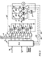
- Figure 3 illustrates the invention as applied to a power interface circuit 13' for a normally deenergized load 11'.
- the logic level actuation signals a, b and c are applied to the appropriate relay coils 17', without inversion, through OR circuits 31.
- the microprocessor 21 when not in the test mode, applies low level logic signals to the OR circuits 31 so that the actuation signals, when generated, are gated to the associated relay coil.
- the microprocessor sequentially generates patterns of high level logic signals which energize the coil 17' of the associated relay to close the appropriate normally open contacts 15' in power interface circuit 13'.
- current detectors 27' monitor the current flowing through the three groups 19' of relay contacts and feed the readings back to the microprocessor 21 through leads 29'.
- the relays associated with both sets of normally open contacts 15 must be energized so that a current flows through the associated current detector 27. This also results in energizing the load 11'. This momentary energization of the normally deenergized load during testing is tolerable for some engineered safeguard functions. For those situations where even momentary energization cannot be tolerated, the arrangement reduces the energizing voltage below that required to actuate the load 11' while providing sufficient current to be detected by the current detectors 27.
- gate circuits such as the NAND circuits in Figure 2 and the OR circuits of Figure 3 is dependent upon whether the load is normally energized or deenergized and upon the desired failure state. For instance, by using NAND gates in Figure 2 with a normally energized load, failure of the microprocessor so that high level gating signals are not applied to the gates, results in actuation, in this case deenergization, of the load. On the other hand, by using OR gates in Figure 3 with a normally deenergized load, failure of the tester which applies low level signals to the OR gates during normal operation anyway, does not result in actuation of the load. In either case, generation of two out of three actuation signals a, b and c always results in actuation of the load.
- Table I illustrates a sequence of step signals generated by the microprocessor 21 for testing the circuit of Figure 2 and the expected results from each test sequence.
- Step 1 is the normal operating mode wherein the microprocessor applies high level signals to all of the NAND circuits 23 in Figure 2 so that any actuation signals a, b, or c generated by the logic trains 7 are gated to the appropriate relay coils 17. Steps 8 through 13 of Table I are omitted if the load may not be deenergized during testing.
- Table II illustrates a test sequence and the expected results for the circuit of Figure 3.
- step 1 represents the normal state between tests when low level signals are applied to all of the OR circuits 31 of Figure 2 so that any actuation signals a, b or c from the logic trains 7 may be gated to the appropriate relay coil. While steps 2 through 7 in which only one coil at a time is energized normally do not result in any current through the detectors 27, they are useful in detecting certain malfunctions. For instance, if the other set of contacts in the group is stuck closed or the coil associated with that other set of contacts is energized due to some malfunction, a circuit is completed and would be detected by the associated current detector 27.
- the microprocessor 21 compares the current detected by the current detectors 27 with expected values for each combination of test signals generated. The results of these comparisons are used by the microprocessor to generate an output status signal indicating whether or not any malfunctions were detected during the test. Since the microprocessor performs the tests rapidly and does not disable the protection function, tests can be run frequently to closely monitor circuit conditions.
- relays as the switches
- other types of switching devices could also be used, such as for example, triacs, SCRs, or power MOSFETs.
- the relays inherently provide electrical isolation by means of the coil-contact separation.
- the solid state switches may be electrically isolated to maintain separation of the channels by, for instance, opto-isolators or other suitable protection grade isolation devices.
Landscapes
- Physics & Mathematics (AREA)
- Engineering & Computer Science (AREA)
- High Energy & Nuclear Physics (AREA)
- Emergency Management (AREA)
- Plasma & Fusion (AREA)
- General Engineering & Computer Science (AREA)
- Business, Economics & Management (AREA)
- General Physics & Mathematics (AREA)
- Automation & Control Theory (AREA)
- Testing Electric Properties And Detecting Electric Faults (AREA)
- Monitoring And Testing Of Nuclear Reactors (AREA)
- Tests Of Electronic Circuits (AREA)
- Testing And Monitoring For Control Systems (AREA)
- Safety Devices In Control Systems (AREA)
Applications Claiming Priority (2)
| Application Number | Priority Date | Filing Date | Title |
|---|---|---|---|
| US06/793,382 US4664870A (en) | 1985-10-31 | 1985-10-31 | Testable voted logic power interface |
| US793382 | 1985-10-31 |
Publications (1)
| Publication Number | Publication Date |
|---|---|
| EP0223461A1 true EP0223461A1 (fr) | 1987-05-27 |
Family
ID=25159790
Family Applications (1)
| Application Number | Title | Priority Date | Filing Date |
|---|---|---|---|
| EP86308456A Withdrawn EP0223461A1 (fr) | 1985-10-31 | 1986-10-30 | Logique de décision testable pour interface de puissance |
Country Status (3)
| Country | Link |
|---|---|
| US (1) | US4664870A (fr) |
| EP (1) | EP0223461A1 (fr) |
| JP (1) | JPH0652286B2 (fr) |
Cited By (4)
| Publication number | Priority date | Publication date | Assignee | Title |
|---|---|---|---|---|
| EP0665479A1 (fr) * | 1994-01-31 | 1995-08-02 | Sextant Avionique S.A. | Interrupteur composite de sécurité |
| US5859034A (en) * | 1996-12-04 | 1999-01-12 | Celltech Therapeutics, Limited | Tri-substituted phenyl compounds which have useful pharmaceutical activity |
| WO2001041153A1 (fr) * | 1999-12-06 | 2001-06-07 | Westinghouse Electric Company Llc | Systeme de mise sous tension permettant d'actionner un systeme de securite et procede d'essais de ce systeme |
| EP1772786A3 (fr) * | 2005-10-03 | 2007-06-06 | Westinghouse Electric Company LLC | Carte de circuit imprimé pour un système de protection d'un réacteur nucléaire |
Families Citing this family (11)
| Publication number | Priority date | Publication date | Assignee | Title |
|---|---|---|---|---|
| US4832900A (en) * | 1986-02-18 | 1989-05-23 | Westinghouse Electric Corp. | Test tool for a reactor vessel fluid level instrumentation |
| US4762663A (en) * | 1986-04-08 | 1988-08-09 | Westinghouse Electric Corp. | Self-testing monitoring circuit |
| US4843537A (en) * | 1986-07-04 | 1989-06-27 | Hitachi, Ltd. | Control system |
| US4783307A (en) * | 1987-03-05 | 1988-11-08 | Commonwealth Edison Company | Reactor control system verification |
| GB2251991A (en) * | 1991-01-18 | 1992-07-22 | Nnc Ltd | Electrical safety system for de-energising a load in response to a plurality of simultaneous fault conditions |
| US6292523B1 (en) * | 1997-06-06 | 2001-09-18 | Westinghouse Electric Company Llc | Digital engineered safety features actuation system |
| KR100399759B1 (ko) * | 2000-11-01 | 2003-09-29 | 한국과학기술원 | 원자력 발전소의 디지털 온라인 능동 시험 발전소 보호시스템 및 그 방법 |
| US6701258B2 (en) * | 2002-05-13 | 2004-03-02 | Entek Ird International Corporation | Modular monitoring and protection system with distributed voting logic |
| US6714880B2 (en) * | 2002-05-13 | 2004-03-30 | Entek Ird International Corporation | Multi-alarm monitoring and protection system |
| JP2014186795A (ja) * | 2013-03-21 | 2014-10-02 | Honda Motor Co Ltd | 車両用故障判定装置 |
| CN107045896B (zh) * | 2016-02-05 | 2018-12-28 | 中国船舶重工集团公司第七一三研究所 | 一种顺序可控储能装置和储能方法 |
Citations (3)
| Publication number | Priority date | Publication date | Assignee | Title |
|---|---|---|---|---|
| US3967257A (en) * | 1973-01-09 | 1976-06-29 | Westinghouse Electric Corporation | Current monitor circuits |
| FR2494034A1 (fr) * | 1980-11-10 | 1982-05-14 | Otis Elevator Co | Dispositif d'excitation de relais a l'abri des defaillances |
| US4415884A (en) * | 1981-10-07 | 1983-11-15 | Combustion Engineering, Inc. | Diagnostic circuit for programmable logic safety control systems |
Family Cites Families (8)
| Publication number | Priority date | Publication date | Assignee | Title |
|---|---|---|---|---|
| DE1176288B (de) * | 1962-06-01 | 1964-08-20 | Siemens Ag | Reaktorsicherheitsschaltung nach dem 2-von-3-System |
| US3424652A (en) * | 1966-04-26 | 1969-01-28 | Kernforschung Gmbh Ges Fuer | Method and device for the supervision of installations,in particular safety switching system of nuclear reactors |
| US3437556A (en) * | 1967-10-23 | 1969-04-08 | Combustion Eng | Test circuit for reactor safety control system |
| US3748540A (en) * | 1971-09-02 | 1973-07-24 | Gen Electric | Testing and monitoring system for redundant trip devices |
| DE3126587A1 (de) * | 1980-07-07 | 1982-05-27 | Imperial Chemical Industries Ltd., London | "abschaltsystem" |
| FR2494877A1 (fr) * | 1980-11-26 | 1982-05-28 | Commissariat Energie Atomique | Systeme logique de securite pour declencher l'action de protection d'un actionneur de surete |
| US4434132A (en) * | 1981-04-09 | 1984-02-28 | Westinghouse Electric Corp. | Power supply with nuclear reactor |
| SE8305262L (sv) * | 1982-12-14 | 1984-06-15 | Gen Electric | Universellt logikkort |
-
1985
- 1985-10-31 US US06/793,382 patent/US4664870A/en not_active Expired - Lifetime
-
1986
- 1986-10-30 EP EP86308456A patent/EP0223461A1/fr not_active Withdrawn
- 1986-10-31 JP JP61260512A patent/JPH0652286B2/ja not_active Expired - Fee Related
Patent Citations (3)
| Publication number | Priority date | Publication date | Assignee | Title |
|---|---|---|---|---|
| US3967257A (en) * | 1973-01-09 | 1976-06-29 | Westinghouse Electric Corporation | Current monitor circuits |
| FR2494034A1 (fr) * | 1980-11-10 | 1982-05-14 | Otis Elevator Co | Dispositif d'excitation de relais a l'abri des defaillances |
| US4415884A (en) * | 1981-10-07 | 1983-11-15 | Combustion Engineering, Inc. | Diagnostic circuit for programmable logic safety control systems |
Non-Patent Citations (2)
| Title |
|---|
| ELEKTRONIK, vol. 26, no. 12, 1977, pages 61-65, DE; K. MEYER: "Sicherheitssysteme für elektronisch gesteuerte Anlagen" * |
| IEEE MICRO, vol. 4, no. 6, December 1984, pages 22-33, IEEE, New York, US; W.F. McGILL et al.: "Fault tolerance in continuous process control" * |
Cited By (5)
| Publication number | Priority date | Publication date | Assignee | Title |
|---|---|---|---|---|
| EP0665479A1 (fr) * | 1994-01-31 | 1995-08-02 | Sextant Avionique S.A. | Interrupteur composite de sécurité |
| FR2715738A1 (fr) * | 1994-01-31 | 1995-08-04 | Sextant Avionique | Interrupteur composite de sécurité. |
| US5859034A (en) * | 1996-12-04 | 1999-01-12 | Celltech Therapeutics, Limited | Tri-substituted phenyl compounds which have useful pharmaceutical activity |
| WO2001041153A1 (fr) * | 1999-12-06 | 2001-06-07 | Westinghouse Electric Company Llc | Systeme de mise sous tension permettant d'actionner un systeme de securite et procede d'essais de ce systeme |
| EP1772786A3 (fr) * | 2005-10-03 | 2007-06-06 | Westinghouse Electric Company LLC | Carte de circuit imprimé pour un système de protection d'un réacteur nucléaire |
Also Published As
| Publication number | Publication date |
|---|---|
| JPS62106378A (ja) | 1987-05-16 |
| US4664870A (en) | 1987-05-12 |
| JPH0652286B2 (ja) | 1994-07-06 |
Similar Documents
| Publication | Publication Date | Title |
|---|---|---|
| US4664870A (en) | Testable voted logic power interface | |
| EP0202052B1 (fr) | Système et méthode de protection de réacteur auxiliaire | |
| US4804515A (en) | Distributed microprocessor based sensor signal processing system for a complex process | |
| US3892954A (en) | Programmable, tester for protection and safeguards logic functions | |
| KR890002380B1 (ko) | 원자로 트립장치 | |
| EP0192027B1 (fr) | Circuit d'interface de puissance testable tolérant les défauts pour la commande d'équipement d'installations de processus | |
| US4020488A (en) | Alarm and/or control apparatus | |
| EP0145188A2 (fr) | Système de protection à plusieurs canaux avec des éléments logiques à noyau magnétique saturable | |
| EP0241270B1 (fr) | Circuit de surveillance autotesté | |
| US6292523B1 (en) | Digital engineered safety features actuation system | |
| US4752886A (en) | Method for on-line testing of load control circuitry and the associated load | |
| US4687623A (en) | Self-compensating voted logic power interface with tester | |
| US4696785A (en) | Testable voted logic power circuit and method of testing the same | |
| EP0221775B1 (fr) | Logique de décision pour circuit de puissance et sa méthode de test | |
| US4683105A (en) | Testable, fault-tolerant power interface circuit for normally de-energized loads | |
| US4200864A (en) | Process control plant comprising processing of signals | |
| KR102003748B1 (ko) | 공통유형고장에 강인하고 기기 상태/성능감시를 특징으로 하는 안전계통 현장기기 현장 작동모듈 및 그의 개발 방법 | |
| KR20020058084A (ko) | 통전-작동형 공학적 안전 설비 작동 시스템 및 이를 위한테스팅 방법 | |
| US2988694A (en) | Automatic fault locator | |
| SU883805A1 (ru) | Устройство дл автоматической проверки параметров электрических цепей | |
| JPS63140305A (ja) | 制御保護装置 | |
| WO2025017495A1 (fr) | Dispositif de surveillance d'état amélioré pour surveiller l'état d'un actionneur | |
| RU2066867C1 (ru) | Устройство тестового контроля комплекта защит фильтров высших гармоник | |
| KR980011521A (ko) | Asic을 이용한 원자로 이상상태 검출장치 및 방법 | |
| RU2067776C1 (ru) | Способ автоматической защиты машины по вибрации и устройство для его осуществления |
Legal Events
| Date | Code | Title | Description |
|---|---|---|---|
| PUAI | Public reference made under article 153(3) epc to a published international application that has entered the european phase |
Free format text: ORIGINAL CODE: 0009012 |
|
| AK | Designated contracting states |
Kind code of ref document: A1 Designated state(s): BE CH FR GB IT LI SE |
|
| 17P | Request for examination filed |
Effective date: 19871127 |
|
| 17Q | First examination report despatched |
Effective date: 19890228 |
|
| STAA | Information on the status of an ep patent application or granted ep patent |
Free format text: STATUS: THE APPLICATION IS DEEMED TO BE WITHDRAWN |
|
| 18D | Application deemed to be withdrawn |
Effective date: 19900501 |
|
| RIN1 | Information on inventor provided before grant (corrected) |
Inventor name: HAGER, ROBERT EDWARD |