EP0223471A2 - Conduits de distribution de fluide - Google Patents
Conduits de distribution de fluide Download PDFInfo
- Publication number
- EP0223471A2 EP0223471A2 EP86308532A EP86308532A EP0223471A2 EP 0223471 A2 EP0223471 A2 EP 0223471A2 EP 86308532 A EP86308532 A EP 86308532A EP 86308532 A EP86308532 A EP 86308532A EP 0223471 A2 EP0223471 A2 EP 0223471A2
- Authority
- EP
- European Patent Office
- Prior art keywords
- air
- duct
- fluid flow
- air inlet
- aircraft
- Prior art date
- Legal status (The legal status is an assumption and is not a legal conclusion. Google has not performed a legal analysis and makes no representation as to the accuracy of the status listed.)
- Granted
Links
Images

Classifications
-
- B—PERFORMING OPERATIONS; TRANSPORTING
- B64—AIRCRAFT; AVIATION; COSMONAUTICS
- B64D—EQUIPMENT FOR FITTING IN OR TO AIRCRAFT; FLIGHT SUITS; PARACHUTES; ARRANGEMENT OR MOUNTING OF POWER PLANTS OR PROPULSION TRANSMISSIONS IN AIRCRAFT
- B64D13/00—Arrangements or adaptations of air-treatment apparatus for aircraft crew or passengers, or freight space
-
- B—PERFORMING OPERATIONS; TRANSPORTING
- B64—AIRCRAFT; AVIATION; COSMONAUTICS
- B64D—EQUIPMENT FOR FITTING IN OR TO AIRCRAFT; FLIGHT SUITS; PARACHUTES; ARRANGEMENT OR MOUNTING OF POWER PLANTS OR PROPULSION TRANSMISSIONS IN AIRCRAFT
- B64D13/00—Arrangements or adaptations of air-treatment apparatus for aircraft crew or passengers, or freight space
- B64D13/06—Arrangements or adaptations of air-treatment apparatus for aircraft crew or passengers, or freight space the air being conditioned
- B64D2013/0603—Environmental Control Systems
- B64D2013/064—Environmental Control Systems comprising more than one system, e.g. dual systems
-
- Y—GENERAL TAGGING OF NEW TECHNOLOGICAL DEVELOPMENTS; GENERAL TAGGING OF CROSS-SECTIONAL TECHNOLOGIES SPANNING OVER SEVERAL SECTIONS OF THE IPC; TECHNICAL SUBJECTS COVERED BY FORMER USPC CROSS-REFERENCE ART COLLECTIONS [XRACs] AND DIGESTS
- Y10—TECHNICAL SUBJECTS COVERED BY FORMER USPC
- Y10S—TECHNICAL SUBJECTS COVERED BY FORMER USPC CROSS-REFERENCE ART COLLECTIONS [XRACs] AND DIGESTS
- Y10S138/00—Pipes and tubular conduits
- Y10S138/04—Air conditioning
-
- Y—GENERAL TAGGING OF NEW TECHNOLOGICAL DEVELOPMENTS; GENERAL TAGGING OF CROSS-SECTIONAL TECHNOLOGIES SPANNING OVER SEVERAL SECTIONS OF THE IPC; TECHNICAL SUBJECTS COVERED BY FORMER USPC CROSS-REFERENCE ART COLLECTIONS [XRACs] AND DIGESTS
- Y10—TECHNICAL SUBJECTS COVERED BY FORMER USPC
- Y10T—TECHNICAL SUBJECTS COVERED BY FORMER US CLASSIFICATION
- Y10T137/00—Fluid handling
- Y10T137/8593—Systems
- Y10T137/85938—Non-valved flow dividers
Definitions
- This invention relates to fluid flow distribution ducts. Primarily, though not exclusively, it relates to fluid flow distribution ducts for use in aircraft air conditioning systems.
- ECS Environmental Control System
- a fluid flow distribution duct for an aircraft air-conditioning system comprising first air inlet duct means for receiving air from a first air supply source, second air inlet duct means for receiving air from a second air supply source, said first and second air inlet duct means including air inlet flow dividing means forming first and second fluid flow passageway means of substantially equal cross-sectional area for communicating with first and second air outlet duct means, the arrangement being such that the flow in the respective first and second air inlet duct means is divided into substantially equal fluid flow portions for balanced distribution to port and starboard sides of the aircraft.
- said first or second air inlet duct means includes third air outlet duct means for receiving at least a portion of said air from said first or second air supply source for transmittal to the aircraft cockpit or flight deck the residual mass air flow divided into substantially equal fluid flow portions for balanced distribution to port and starboard sides of the aircraft cabin.
- an aircraft air-conditioning system said system including first and second air supply source means for the supply of temperature regulated air, the or each supply source being in communication with fluid flow distribution duct mews for balanced distribution of the respective flows to port and starboard sides of the aircraft characterised in that said fluid flow distribution duct means comprises first air inlet duct means for receiving air from said first air supply source, second air inlet duct means for receiving air from said second air inlet supply source, said first and second air inlet duct means including air inlet flow dividing means of substantially equal cross-sectional area and communicating with first and second air outlet duct means providing fluid flow outlet means, the arrangement being such that flow from said first and second air supply sources is each divided into substantially equal fluid flow portions for balanced distribution to port and starboard sides of the aircraft and mixing of the resultant flows occurs as the said flow issues from the outlet duct.
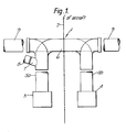
- Figure 1 illustrates, in diagrammatic plan form a portion of an aircraft air conditioning system 1 according to the present invention in which the system is equally disposed about the centre line 2 of an aircraft.
- the system comprises an environmental control system (ECS) unit 3 located on the aircraft port side and a further ECS unit 4 correspondingly located to starboard.
- ECS environmental control system
- Fluid flow ducts 5a and 5b interconnect the ECS units to a distribution duct assembly 6 having a stub duct 7 which provides conditioning air flow to the aircraft cockpit or flight deck via a duct 8 and to the passenger cabin via two riser stub ducts 9 located on port and starboard sides of the cabin.
- Each ECS unit supplies independent mass flow to the air conditioning system and the temperature range of that flow varies between 3 0 c and 70 0 c dependent upon requirements.
- Flow temperatures between port and starboard ducts 5a and 5b may vary as a function of demand since temperature in the port duct 5a is solely determined by cockpit or flight deck requirements whereas that in the starboard duct 5b arises from cabin conditioning requirements.
- the distribution ducting of the present invention overcomes these shortcomings by means of a novel arrangement whereby the respective flows entering the distribution duct are each divided into separate duct portions of equal cross-sectional area, each duct portion transmitting its respective divided flow portion to either port or starboard outlet duct openings where mixing of the separately issuing flows will occur such that there will be a balanced fluid flow supply in temperature and pressure terms to each side of the cabin, thus minimising the pressure losses associated with mixing within the distribution duct whilst achieving compact duct proportions.
- This compact and efficient arrangement is more clearly demonstrated by reference to Figures 2 to 5 inclusive which for reasons of clarity illustrates the distribution duct assembly 6 in isolation from the other component parts of the system.
- the assembly comprises spaced apart duct inlet portions 10 and 11 and duct outlet portions 12 and 13, the duct outlet portions lying substantially at right angles to the duct inlet portions and disposed about a common axis 14.
- the duct inlet portions are each of constant circular cross-section over a length 15 and the duct outlet portions each over a length 16.
- the duct inlet portion 10 includes an outwardly directed outlet duct portion 7.
- the duct inlet portions further include horizontal diaphragm webs 18a and 18b, each constituting a septum, ie, they divide the inlet duct portion 10 into upper and lower sealed semi-circular ducts 18c and 18d and inlet duct portion 11 into similar semi-circular ducts 18e and 18f.
- the web 18a commences immediately beyond the duct portion 7, the web 18b only a distance 19 from the inlet opening of duct 11.
- the semi-circular duct portions divide out and are configured such that the upper duct 18c provides an upper flow passage to the outlet duct portion 12 and the lower duct 18d a lower flow passage to the outlet duct portion 13. Similarly, the upper duct portion 18e provides an upper flow passage to the outlet duct portion 13 and the lower duct A a lower flow passage to the outlet duct portion 12.
- each includes its own diaphragm web 18a, 18b, over the region of separation.
Landscapes
- Health & Medical Sciences (AREA)
- General Health & Medical Sciences (AREA)
- Pulmonology (AREA)
- Engineering & Computer Science (AREA)
- Aviation & Aerospace Engineering (AREA)
- Duct Arrangements (AREA)
- Central Air Conditioning (AREA)
Applications Claiming Priority (2)
| Application Number | Priority Date | Filing Date | Title |
|---|---|---|---|
| GB8527201 | 1985-11-05 | ||
| GB858527201A GB8527201D0 (en) | 1985-11-05 | 1985-11-05 | Fluid flow distribution ducts |
Publications (3)
| Publication Number | Publication Date |
|---|---|
| EP0223471A2 true EP0223471A2 (fr) | 1987-05-27 |
| EP0223471A3 EP0223471A3 (en) | 1989-02-22 |
| EP0223471B1 EP0223471B1 (fr) | 1992-03-25 |
Family
ID=10587725
Family Applications (1)
| Application Number | Title | Priority Date | Filing Date |
|---|---|---|---|
| EP19860308532 Expired - Lifetime EP0223471B1 (fr) | 1985-11-05 | 1986-10-31 | Conduits de distribution de fluide |
Country Status (7)
| Country | Link |
|---|---|
| US (1) | US4741255A (fr) |
| EP (1) | EP0223471B1 (fr) |
| BR (1) | BR8605472A (fr) |
| CA (1) | CA1270143A (fr) |
| DE (1) | DE3684559D1 (fr) |
| ES (1) | ES2029993T3 (fr) |
| GB (1) | GB8527201D0 (fr) |
Cited By (1)
| Publication number | Priority date | Publication date | Assignee | Title |
|---|---|---|---|---|
| EP0888965A3 (fr) * | 1997-07-04 | 2000-04-12 | DaimlerChrysler Aerospace Airbus Gesellschaft mit beschränkter Haftung | Buse d'aération pour la surveillance de la température et des fumées |
Families Citing this family (6)
| Publication number | Priority date | Publication date | Assignee | Title |
|---|---|---|---|---|
| JP2816577B2 (ja) * | 1989-10-31 | 1998-10-27 | 芳則 織部 | ダクト各吐出口の風速均一方法及びその装置 |
| US5253484A (en) * | 1991-08-22 | 1993-10-19 | The Boeing Company | High reliability avionic cooling system |
| US5630447A (en) * | 1995-10-06 | 1997-05-20 | Endot Industries, Inc. | Pipe for geothermal heating and cooling systems |
| BRPI0418158A (pt) * | 2003-12-30 | 2007-04-17 | Airbus Gmbh | método e sistema de linha para condicionamento de ar de um compartimento de carga ou uma cabine de uma aeronave |
| DE102006014572B4 (de) * | 2006-03-29 | 2008-08-28 | Airbus Deutschland Gmbh | Vorrichtung und Verfahren zur Luftverteilung in einem Frachtflugzeug |
| US20090084896A1 (en) * | 2007-09-27 | 2009-04-02 | Hamilton Sundstrand Corporation | Cabin air system for aviation electronics |
Family Cites Families (8)
| Publication number | Priority date | Publication date | Assignee | Title |
|---|---|---|---|---|
| GB527025A (en) * | 1938-05-04 | 1940-10-01 | Sulzer Ag | Improvements in or relating to heating apparatus for the cabins of aircraft |
| US2912189A (en) * | 1955-12-29 | 1959-11-10 | Pouit Robert | Jet propelled aircraft with jet flaps |
| US3262659A (en) * | 1964-04-29 | 1966-07-26 | John E Copeland | Thrust control apparatus |
| US3432123A (en) * | 1967-04-03 | 1969-03-11 | Dehavilland Aircraft | Cross ducting system for augmentor wing aircraft |
| US3802825A (en) * | 1969-11-11 | 1974-04-09 | Windmoeller & Hoelscher | Extruder for plastic material having a flow divider and means for maintaining the same distribution of temperature gradients in the divided flow |
| US3711044A (en) * | 1971-03-17 | 1973-01-16 | Garrett Corp | Automatic interface control system |
| US4546939A (en) * | 1982-05-27 | 1985-10-15 | Lockheed Corporation | Energy efficient ECS powered by a variable voltage/variable frequency power system |
| US4517813A (en) * | 1983-07-05 | 1985-05-21 | The Boeing Company | Air conditioning system and air mixing/water separation apparatus therein |
-
1985
- 1985-11-05 GB GB858527201A patent/GB8527201D0/en active Pending
-
1986
- 1986-10-31 EP EP19860308532 patent/EP0223471B1/fr not_active Expired - Lifetime
- 1986-10-31 DE DE8686308532T patent/DE3684559D1/de not_active Expired - Fee Related
- 1986-10-31 ES ES198686308532T patent/ES2029993T3/es not_active Expired - Lifetime
- 1986-11-04 CA CA000522136A patent/CA1270143A/fr not_active Expired
- 1986-11-05 US US06/927,022 patent/US4741255A/en not_active Expired - Fee Related
- 1986-11-05 BR BR8605472A patent/BR8605472A/pt not_active IP Right Cessation
Cited By (1)
| Publication number | Priority date | Publication date | Assignee | Title |
|---|---|---|---|---|
| EP0888965A3 (fr) * | 1997-07-04 | 2000-04-12 | DaimlerChrysler Aerospace Airbus Gesellschaft mit beschränkter Haftung | Buse d'aération pour la surveillance de la température et des fumées |
Also Published As
| Publication number | Publication date |
|---|---|
| BR8605472A (pt) | 1987-08-11 |
| EP0223471A3 (en) | 1989-02-22 |
| EP0223471B1 (fr) | 1992-03-25 |
| CA1270143A (fr) | 1990-06-12 |
| ES2029993T3 (es) | 1992-10-16 |
| DE3684559D1 (de) | 1992-04-30 |
| US4741255A (en) | 1988-05-03 |
| GB8527201D0 (en) | 1985-12-11 |
Similar Documents
| Publication | Publication Date | Title |
|---|---|---|
| EP0292033B1 (fr) | Tuyère double pour dispositif de ventilation de cabine | |
| EP2671801B1 (fr) | Système de conditionnement d'air et procédé pour l'opérer | |
| EP3728036B1 (fr) | Ensemble de distribution de circulation de plafond pour cabine d'aéronef | |
| EP0507725B1 (fr) | Régulateur de débit de l'air d'échappement avec équilibrage des débits | |
| US4741255A (en) | Fluid flow distribution ducts | |
| CN104066640A (zh) | 车辆空调管道和铁道车辆 | |
| US5884873A (en) | Suction generator system in an aircraft for maintaining a laminar boundary flow | |
| US10315775B2 (en) | Duct structure which discharges air through air pressure regulating valve and aircraft | |
| GB2242262A (en) | Heating and ventilating apparatus for an automotive vehicle cabin, with separate means for regulating the temperature of air to different parts of the cabin | |
| CA2632624C (fr) | Systeme de conditionnement d'air pour aeronef dote de dispositifs de refoulement cycloniques | |
| EP4036014B1 (fr) | Ensemble fuselage pour aéronef | |
| US20100087131A1 (en) | Integrated air supply device | |
| US9499276B2 (en) | Helicopter with engine air intakes | |
| RU2616490C2 (ru) | Система кондиционирования воздуха транспортного средства и оснащенное этой системой железнодорожное транспортное средство | |
| US9011216B1 (en) | Diversion directional nozzle | |
| US8876580B2 (en) | Uniform flow supply duct and associated method of sizing restrictor plates | |
| EP3800156B1 (fr) | Système de refroidissement pour affichages visuels électroniques de cabine d'ascenseur et son procédé | |
| US20200269986A1 (en) | Air conditioning piping structure for aircraft and air conditioning system | |
| CA3000736A1 (fr) | Appareil et systeme de detection de temperature d'air de cabine d'aeronef utilisant un flux d'air passif | |
| US2991706A (en) | System for distributing conditioned air in aircraft | |
| RU2092742C1 (ru) | Раздаточный короб системы кондиционирования воздуха летательного аппарата | |
| US11046441B2 (en) | Adaptive plate-fin heat exchanger | |
| US12330795B2 (en) | Humidification system for aircraft | |
| US20250100694A1 (en) | Aircraft cabin air distribution system | |
| EP4163207B1 (fr) | Système d'humidification pour aéronef |
Legal Events
| Date | Code | Title | Description |
|---|---|---|---|
| PUAI | Public reference made under article 153(3) epc to a published international application that has entered the european phase |
Free format text: ORIGINAL CODE: 0009012 |
|
| 17P | Request for examination filed |
Effective date: 19861110 |
|
| AK | Designated contracting states |
Kind code of ref document: A2 Designated state(s): DE ES FR GB IT |
|
| PUAL | Search report despatched |
Free format text: ORIGINAL CODE: 0009013 |
|
| AK | Designated contracting states |
Kind code of ref document: A3 Designated state(s): DE ES FR GB IT |
|
| 17Q | First examination report despatched |
Effective date: 19900808 |
|
| ITF | It: translation for a ep patent filed | ||
| GRAA | (expected) grant |
Free format text: ORIGINAL CODE: 0009210 |
|
| AK | Designated contracting states |
Kind code of ref document: B1 Designated state(s): DE ES FR GB IT |
|
| ET | Fr: translation filed | ||
| REF | Corresponds to: |
Ref document number: 3684559 Country of ref document: DE Date of ref document: 19920430 |
|
| RAP4 | Party data changed (patent owner data changed or rights of a patent transferred) |
Owner name: BRITISH AEROSPACE PUBLIC LIMITED COMPANY |
|
| REG | Reference to a national code |
Ref country code: ES Ref legal event code: FG2A Ref document number: 2029993 Country of ref document: ES Kind code of ref document: T3 |
|
| PLBE | No opposition filed within time limit |
Free format text: ORIGINAL CODE: 0009261 |
|
| STAA | Information on the status of an ep patent application or granted ep patent |
Free format text: STATUS: NO OPPOSITION FILED WITHIN TIME LIMIT |
|
| 26N | No opposition filed | ||
| PGFP | Annual fee paid to national office [announced via postgrant information from national office to epo] |
Ref country code: FR Payment date: 19930914 Year of fee payment: 8 |
|
| PGFP | Annual fee paid to national office [announced via postgrant information from national office to epo] |
Ref country code: GB Payment date: 19930916 Year of fee payment: 8 |
|
| PGFP | Annual fee paid to national office [announced via postgrant information from national office to epo] |
Ref country code: DE Payment date: 19930920 Year of fee payment: 8 |
|
| PGFP | Annual fee paid to national office [announced via postgrant information from national office to epo] |
Ref country code: ES Payment date: 19930929 Year of fee payment: 8 |
|
| ITTA | It: last paid annual fee | ||
| PG25 | Lapsed in a contracting state [announced via postgrant information from national office to epo] |
Ref country code: GB Effective date: 19941031 |
|
| PG25 | Lapsed in a contracting state [announced via postgrant information from national office to epo] |
Ref country code: ES Free format text: LAPSE BECAUSE OF EXPIRATION OF PROTECTION Effective date: 19941102 |
|
| GBPC | Gb: european patent ceased through non-payment of renewal fee |
Effective date: 19941031 |
|
| PG25 | Lapsed in a contracting state [announced via postgrant information from national office to epo] |
Ref country code: FR Effective date: 19950630 |
|
| PG25 | Lapsed in a contracting state [announced via postgrant information from national office to epo] |
Ref country code: DE Effective date: 19950701 |
|
| REG | Reference to a national code |
Ref country code: FR Ref legal event code: ST |
|
| REG | Reference to a national code |
Ref country code: ES Ref legal event code: FD2A Effective date: 19990601 |
|
| PG25 | Lapsed in a contracting state [announced via postgrant information from national office to epo] |
Ref country code: IT Free format text: LAPSE BECAUSE OF NON-PAYMENT OF DUE FEES Effective date: 20051031 |