EP0223480A2 - Unité de rive avec partie détachable - Google Patents
Unité de rive avec partie détachable Download PDFInfo
- Publication number
- EP0223480A2 EP0223480A2 EP86308560A EP86308560A EP0223480A2 EP 0223480 A2 EP0223480 A2 EP 0223480A2 EP 86308560 A EP86308560 A EP 86308560A EP 86308560 A EP86308560 A EP 86308560A EP 0223480 A2 EP0223480 A2 EP 0223480A2
- Authority
- EP
- European Patent Office
- Prior art keywords
- verge
- unit
- roof
- units
- tiles
- Prior art date
- Legal status (The legal status is an assumption and is not a legal conclusion. Google has not performed a legal analysis and makes no representation as to the accuracy of the status listed.)
- Granted
Links
- 239000000463 material Substances 0.000 claims description 4
- 230000000295 complement effect Effects 0.000 claims description 3
- 239000004033 plastic Substances 0.000 claims description 3
- 229920003023 plastic Polymers 0.000 claims description 3
- 238000005253 cladding Methods 0.000 description 2
- 238000004519 manufacturing process Methods 0.000 description 2
- 238000000034 method Methods 0.000 description 2
- XLYOFNOQVPJJNP-UHFFFAOYSA-N water Substances O XLYOFNOQVPJJNP-UHFFFAOYSA-N 0.000 description 2
- 230000004308 accommodation Effects 0.000 description 1
- 238000006243 chemical reaction Methods 0.000 description 1
- 238000010276 construction Methods 0.000 description 1
- 238000003780 insertion Methods 0.000 description 1
- 230000037431 insertion Effects 0.000 description 1
- 239000002991 molded plastic Substances 0.000 description 1
- 230000000284 resting effect Effects 0.000 description 1
Images

Classifications
-
- E—FIXED CONSTRUCTIONS
- E04—BUILDING
- E04D—ROOF COVERINGS; SKY-LIGHTS; GUTTERS; ROOF-WORKING TOOLS
- E04D13/00—Special arrangements or devices in connection with roof coverings; Protection against birds; Roof drainage ; Sky-lights
- E04D13/15—Trimming strips; Edge strips; Fascias; Expansion joints for roofs
- E04D13/158—Trimming strips; Edge strips; Fascias; Expansion joints for roofs covering the overhang at the eave side, e.g. soffits, or the verge of saddle roofs
- E04D13/1585—Trimming strips; Edge strips; Fascias; Expansion joints for roofs covering the overhang at the eave side, e.g. soffits, or the verge of saddle roofs covering the verge of saddle roofs
Definitions
- This invention relates to improvements to verge units for tiled roofs.
- Verge units are provided at the verge ends of tiled roofs to enclose the free ends of tiles or similar elements with which the roof is covered.
- verge units which are often made from plastics materials or the like, are of interlocking box-like construction, and the aim of using such units is to provide an aesthetically pleasing finish to the tile ends, with a stepped line following the line of overlapping tiles along the upper edge of the verge and a straight line running along the lower edge.
- verge units One of the major problems relating to verge units is that hitherto, it has been usual to provide right or left handed units for fitting to the respective verge ends. Examples of such systems are given in PCT Specification No. WO 81/01583 and U.K. Patent Specification No. 2152967A. However, with these systems the tiler must ensure that the correct handed unit is obtained and fitted at each end. The cost of such units and stocking requirements are thus higher than if a single unit could be used at both ends.
- a verge unit being a tapered channel element symmetrical about its longitudinal axis prior to use, comprising a side, upper and lower wall converging toward one end, and at the divergent end are two inwardly disposed frangible portions, the removal of one of which provides the capability of converting the verge unit for use on a left or right hand verge.
- the verge unit comprises a roof batten end housing which is supported by the side wall of the channel element.
- the roof batten end housing is a U-shaped housing, which is symmetrical about the longitudinal axis of the unit, the back wall of which is a part of the channel element side wall and positioned to allow the housing to slide over a roof batten end.
- the verge unit assembly is secured in position by a U-shaped clip, which is inserted through a combination of slots and apertures symmetrically positioned in the batten end housing and channel element side wall and is adapted to be secured to the roof batten by a plurality of screws or similar fasteners.
- the verge unit may have an inwardly stepped portion at the convergent end, which may have a complementary groove and rib arrangement between the frangible portion and the stepped portion.
- the verge unit is preferably made from a mouldable plastics material.
- the preferred arrangement is a tiled roof having a plurality of overlapping tiles supported by roof battens, and a plurality of overlapping verge units covering the end tiles, with the lower frangible portions of each unit broken out of the previous verge units and the remaining portions resting on the upper walls of the previous verge units such that adjacent units are interconnected, and with the ends of the roof battens positioned inside their housings, the verge unit being secured with clips and fasteners to the battens.
- Verge units are in the main designed for attachment to one end of a roof structure. Only with plain cladding strips or simple channel elements of uniform or tapered configuration has to be possible to utilise a similar unit at each end of a roof.
- verge units for effecting a dry fitting are designed to be aesthetically pleasing when fixed to a roof structure and are of such configuration that they appear to continue the one of tiles over the edge of a roof at the verges thereof.
- the verge unit described below is one such unit; however, by incorporating into a verge unit, having a line of symmetry, frangible break-out portions, it has become possible to utilise the one unit at either end of a roof merely by removing one or other of the break-out portions.
- the units to be described hereinafter are those suitable for use at a right hand end of a roof.
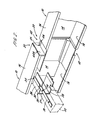
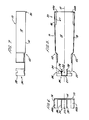
- the verge unit 1 thus, comprises a tapered channel 10 of moulded plastics material, which channel has a line of symmetry 12 indicated in chain-dot line in Figures 5 and 6.
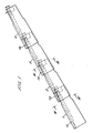
- the channel 10 comprises a main side wall 14, an upper wall 16 and a lower wall 18 which converge towards each other along the length of the unit whereby, in use, a widest end portion 20 of one unit accommodates a reduced end portion 22 of a next in line unit down the roof, as shown in Figures 1, 2, 3 and 4.
- the wall 14 of the unit 1 extends beyond the walls 16 and 18 and at its reduced end portion 22 provides support for a roof batten end housing 24.
- the housing 24 comprises upper and lower wall portions 26 and 28 respectively which extend inwardly from the wall 14 and are equi-spaced one on either side of the line of symmetry 12.
- the housing 24 also comprises a third wall 27 which extends from an end of the wall 14 to adjoin the portions 26 and 28 to form a U-shaped housing the purpose of which will be made clear hereinafter.
- a combination of slots and apertures in the wall 144 and wall portions 26 and 28 enables the insertion of essentially U-shaped clips 30, which, as shown in Figure 3 firmly clamps the unit 1 to the roof when the tile T1 is inserted into the unit 1.
- the wall portion 26 comprises an open ended slot 32 in its end remote from the wall 14 and the wall 14 comprises an aperture 34 adjacent the joint between the wall portion 26 and the wall 14 and an open ended slot 36 in its upper edge 38 thereof the slots 32 and 36 and the aperture 34 being arranged to accommodate clips 30.
- the verge unit 1 is further provided with a stepped feature 42 part way along its length whereby the accommodation of the reduced portion 22 of one unit is further facilitated within the end portion 20 of a next in line unit up the roof as shown in Figures 1 and 2.
- the verge unit 1 also comprises frangible break-out portions 44a and 44b, see Figures 4, 5 and 6, the portion 44a being shown in full line and the portion 44b, which has been removed for the purpose to be described, is shown in chain-dotted line.
- the frangible break-out portion 44a comprises a key portion 45 adapted to slide into a slot 46 of similar cross-section formed in the wall 16 of a next in line units down a roof, see Figures 2 and 4.
- the portion 44b and wall 18 have similar features.
- verge units 1 for use at each end of the roof by breaking out the appropriate portions 44a and 44b and assembling clips 30 as shown in Figure 3 for the right hand verge of the roof.
- Verge units 1 for use at the left hand verge will have clips 30 assembled in the slots and apertures associated with the wall portion 38.
- the tiler then repeats the procedure at the opposite end of the roof utilising the same general configuration of verge unit 1 but with the portions 44b broken out as aforesaid.
- the units 1 also comprise an aperture 60 on their line of symmetry through which a further fastener 62 may be nailed into the end 50 of the batten 52 to give added security to the fixing thereof.
- the units 1 present an aesthetically pleasing appearance to the verge end of a roof with the portions 44a (and 44b not shown) closing the gap between the upper walls 16 of successive units 1, completely enclosing the tile ends T1 following the stepped line of the tiled roof at the upper edge and a straight line along the lower edge. This also increases the protection against water entering the system.
Landscapes
- Engineering & Computer Science (AREA)
- Architecture (AREA)
- Civil Engineering (AREA)
- Structural Engineering (AREA)
- Roof Covering Using Slabs Or Stiff Sheets (AREA)
Applications Claiming Priority (2)
| Application Number | Priority Date | Filing Date | Title |
|---|---|---|---|
| GB8527475 | 1985-07-11 | ||
| GB8527475A GB2182959B (en) | 1985-11-07 | 1985-11-07 | Verge unit with frangible feature |
Publications (3)
| Publication Number | Publication Date |
|---|---|
| EP0223480A2 true EP0223480A2 (fr) | 1987-05-27 |
| EP0223480A3 EP0223480A3 (en) | 1987-10-14 |
| EP0223480B1 EP0223480B1 (fr) | 1990-08-08 |
Family
ID=10587871
Family Applications (1)
| Application Number | Title | Priority Date | Filing Date |
|---|---|---|---|
| EP86308560A Expired EP0223480B1 (fr) | 1985-11-07 | 1986-11-03 | Unité de rive avec partie détachable |
Country Status (6)
| Country | Link |
|---|---|
| US (1) | US4731963A (fr) |
| EP (1) | EP0223480B1 (fr) |
| AU (1) | AU6482786A (fr) |
| DE (1) | DE3673339D1 (fr) |
| ES (1) | ES2017930B3 (fr) |
| GB (1) | GB2182959B (fr) |
Cited By (7)
| Publication number | Priority date | Publication date | Assignee | Title |
|---|---|---|---|---|
| EP0328394A1 (fr) * | 1988-02-09 | 1989-08-16 | Marley Tile AG | Système pour rives de toit |
| AT410454B (de) * | 2001-07-26 | 2003-05-26 | Muhr Harald Ing | Hydraulische isolierung von kragplatten |
| GB2432168A (en) * | 2005-08-04 | 2007-05-16 | Warrington Plastics And Roofin | Dry verge member |
| GB2443509A (en) * | 2006-09-20 | 2008-05-07 | Building Product Design Ltd | A dry verge system for a roof structure |
| WO2011152780A1 (fr) * | 2010-06-03 | 2011-12-08 | Johan Larsson | Profil de tôle métallique pouvant être réuni pour extrémité de pignon de toit |
| GB2586153A (en) * | 2019-08-07 | 2021-02-10 | Hambleside Danelaw Ltd | Verge unit and system for weather-proofing |
| GB2612314A (en) * | 2021-10-26 | 2023-05-03 | Manthorpe Building Products Ltd | Dry verge unit |
Families Citing this family (8)
| Publication number | Priority date | Publication date | Assignee | Title |
|---|---|---|---|---|
| GB2196358B (en) * | 1986-10-17 | 1990-05-16 | Marley Roof Tile | Fixing system for rake verge tiles |
| DE19920398C2 (de) * | 1999-04-28 | 2000-09-21 | Adolf Baumjohann | Ortgangabschluss eines Steildaches |
| DE19933609C1 (de) * | 1999-05-04 | 2000-12-14 | Adolf Baumjohann | Ortgangabschluß eines Steildaches |
| US7246469B2 (en) * | 2002-12-16 | 2007-07-24 | Park Lane Conservatories Ltd. | Multi-piece eaves beam for preassembled glazed roof system |
| US7392623B2 (en) * | 2004-02-03 | 2008-07-01 | Park Lane Conservatories Ltd. | Eaves beam with framing |
| GB2436567B (en) * | 2005-10-31 | 2011-02-16 | Sandtoft Roof Tiles Ltd | Roofing units |
| GB2468066B (en) * | 2005-10-31 | 2010-12-29 | Sandtoft Roof Tiles Ltd | Roofing units |
| GB2444111B (en) * | 2006-11-23 | 2011-09-07 | Manthorpe Building Products Ltd | Cover member |
Family Cites Families (5)
| Publication number | Priority date | Publication date | Assignee | Title |
|---|---|---|---|---|
| US3187464A (en) * | 1962-06-13 | 1965-06-08 | Fiberglass Reinforced Products | Fascia strip |
| FR2109469A5 (fr) * | 1970-10-19 | 1972-05-26 | Bisch Tuileries Sa | |
| GB2014639B (en) * | 1978-02-16 | 1982-10-20 | Hildreth A B | Roof tile edge cover |
| US4442641A (en) * | 1979-10-28 | 1984-04-17 | Marley Tile A.G. | Verge member for a pitched roof and roofing system incorporating the same |
| GB8504876D0 (en) * | 1985-02-26 | 1985-03-27 | Inoventors Ltd | Verge caps for pitched rooves |
-
1985
- 1985-11-07 GB GB8527475A patent/GB2182959B/en not_active Expired
-
1986
- 1986-11-03 ES ES86308560T patent/ES2017930B3/es not_active Expired - Lifetime
- 1986-11-03 DE DE8686308560T patent/DE3673339D1/de not_active Expired - Fee Related
- 1986-11-03 EP EP86308560A patent/EP0223480B1/fr not_active Expired
- 1986-11-05 AU AU64827/86A patent/AU6482786A/en not_active Abandoned
- 1986-11-07 US US06/927,994 patent/US4731963A/en not_active Expired - Fee Related
Cited By (12)
| Publication number | Priority date | Publication date | Assignee | Title |
|---|---|---|---|---|
| EP0328394A1 (fr) * | 1988-02-09 | 1989-08-16 | Marley Tile AG | Système pour rives de toit |
| US5003732A (en) * | 1988-02-09 | 1991-04-02 | Marley Tile A.G. | Roof verge system |
| AT410454B (de) * | 2001-07-26 | 2003-05-26 | Muhr Harald Ing | Hydraulische isolierung von kragplatten |
| GB2432168A (en) * | 2005-08-04 | 2007-05-16 | Warrington Plastics And Roofin | Dry verge member |
| GB2432168B (en) * | 2005-08-04 | 2010-12-29 | Warrington Plastics And Roofing Ltd | Dry verge member |
| GB2443509A (en) * | 2006-09-20 | 2008-05-07 | Building Product Design Ltd | A dry verge system for a roof structure |
| WO2011152780A1 (fr) * | 2010-06-03 | 2011-12-08 | Johan Larsson | Profil de tôle métallique pouvant être réuni pour extrémité de pignon de toit |
| GB2586153A (en) * | 2019-08-07 | 2021-02-10 | Hambleside Danelaw Ltd | Verge unit and system for weather-proofing |
| WO2021023998A1 (fr) * | 2019-08-07 | 2021-02-11 | Hambleside Danelaw Limited | Unité saillie de rive et système de protection contre les intempéries |
| GB2586153B (en) * | 2019-08-07 | 2021-08-25 | Hambleside Danelaw Ltd | Verge unit and system for weatherproofing |
| GB2612314A (en) * | 2021-10-26 | 2023-05-03 | Manthorpe Building Products Ltd | Dry verge unit |
| GB2612314B (en) * | 2021-10-26 | 2023-10-18 | Manthorpe Building Products Ltd | Dry verge unit |
Also Published As
| Publication number | Publication date |
|---|---|
| AU6482786A (en) | 1987-05-14 |
| EP0223480A3 (en) | 1987-10-14 |
| EP0223480B1 (fr) | 1990-08-08 |
| GB8527475D0 (en) | 1985-12-11 |
| DE3673339D1 (de) | 1990-09-13 |
| GB2182959A (en) | 1987-05-28 |
| US4731963A (en) | 1988-03-22 |
| GB2182959B (en) | 1989-10-25 |
| ES2017930B3 (es) | 1991-03-16 |
Similar Documents
| Publication | Publication Date | Title |
|---|---|---|
| EP0223480B1 (fr) | Unité de rive avec partie détachable | |
| US4890432A (en) | Roof tile | |
| EP1211365B1 (fr) | Système de plancher | |
| US5671577A (en) | Roofing shingle | |
| BG61882B1 (bg) | Модулни покриви на сгради | |
| US5388381A (en) | Interlocking building panel | |
| EP0243079B1 (fr) | Linteau | |
| GB2164369A (en) | Verge capping system | |
| EP0329654A1 (fr) | Procédé de revêtement | |
| EP1000206A1 (fr) | Revetement protecteur et decoratif a auto-ventilation pour des murs et des toits | |
| GB2141463A (en) | Jointing member for ridge tiles | |
| EP0020103B1 (fr) | Tuile pour toiture et toit en tuiles | |
| GB2186302A (en) | A cover for a roof verge and a method of providing a cover on a roof verge | |
| JP2799962B2 (ja) | けらば包み材 | |
| JP3617944B2 (ja) | けらば化粧材及び屋根のけらば部の構造 | |
| JPH0736983Y2 (ja) | けらば防水バンド及びけらば側瓦取付構造 | |
| JPH0699987B2 (ja) | タイルブロック製屋根 | |
| GB2152967A (en) | Roof dry verge structures | |
| JPH09119195A (ja) | 屋根構造 | |
| EP0292068A1 (fr) | Procédé de fabrication d'une lucarne et ensemble de construction destiné à la réalisation dudit procédé | |
| JP2980671B2 (ja) | 段葺屋根のけらば部構造 | |
| GB2467000A (en) | Roof tile with different edge thicknesses and lengths | |
| CA1328725C (fr) | Bordereaux en elements de parement imbriques | |
| JP2588045B2 (ja) | 瓦屋根における袖部の施工方法及び袖瓦 | |
| JP2980668B2 (ja) | けらば包み |
Legal Events
| Date | Code | Title | Description |
|---|---|---|---|
| PUAI | Public reference made under article 153(3) epc to a published international application that has entered the european phase |
Free format text: ORIGINAL CODE: 0009012 |
|
| AK | Designated contracting states |
Kind code of ref document: A2 Designated state(s): DE ES FR GB |
|
| PUAL | Search report despatched |
Free format text: ORIGINAL CODE: 0009013 |
|
| AK | Designated contracting states |
Kind code of ref document: A3 Designated state(s): DE ES FR GB |
|
| 17P | Request for examination filed |
Effective date: 19880305 |
|
| 17Q | First examination report despatched |
Effective date: 19891215 |
|
| GRAA | (expected) grant |
Free format text: ORIGINAL CODE: 0009210 |
|
| AK | Designated contracting states |
Kind code of ref document: B1 Designated state(s): DE ES FR GB |
|
| REF | Corresponds to: |
Ref document number: 3673339 Country of ref document: DE Date of ref document: 19900913 |
|
| ET | Fr: translation filed | ||
| PGFP | Annual fee paid to national office [announced via postgrant information from national office to epo] |
Ref country code: ES Payment date: 19901107 Year of fee payment: 5 |
|
| PGFP | Annual fee paid to national office [announced via postgrant information from national office to epo] |
Ref country code: DE Payment date: 19901115 Year of fee payment: 5 |
|
| PGFP | Annual fee paid to national office [announced via postgrant information from national office to epo] |
Ref country code: FR Payment date: 19901129 Year of fee payment: 5 |
|
| PLBE | No opposition filed within time limit |
Free format text: ORIGINAL CODE: 0009261 |
|
| STAA | Information on the status of an ep patent application or granted ep patent |
Free format text: STATUS: NO OPPOSITION FILED WITHIN TIME LIMIT |
|
| 26N | No opposition filed | ||
| PG25 | Lapsed in a contracting state [announced via postgrant information from national office to epo] |
Ref country code: ES Free format text: LAPSE BECAUSE OF NON-PAYMENT OF DUE FEES Effective date: 19911104 |
|
| PG25 | Lapsed in a contracting state [announced via postgrant information from national office to epo] |
Ref country code: FR Effective date: 19920731 |
|
| PG25 | Lapsed in a contracting state [announced via postgrant information from national office to epo] |
Ref country code: DE Effective date: 19920801 |
|
| REG | Reference to a national code |
Ref country code: FR Ref legal event code: ST |
|
| PGFP | Annual fee paid to national office [announced via postgrant information from national office to epo] |
Ref country code: GB Payment date: 19931029 Year of fee payment: 8 |
|
| PG25 | Lapsed in a contracting state [announced via postgrant information from national office to epo] |
Ref country code: GB Effective date: 19941103 |
|
| GBPC | Gb: european patent ceased through non-payment of renewal fee |
Effective date: 19941103 |
|
| REG | Reference to a national code |
Ref country code: ES Ref legal event code: FD2A Effective date: 19921214 |