EP0223528A2 - Pulvérisateur oscillant - Google Patents
Pulvérisateur oscillant Download PDFInfo
- Publication number
- EP0223528A2 EP0223528A2 EP86308716A EP86308716A EP0223528A2 EP 0223528 A2 EP0223528 A2 EP 0223528A2 EP 86308716 A EP86308716 A EP 86308716A EP 86308716 A EP86308716 A EP 86308716A EP 0223528 A2 EP0223528 A2 EP 0223528A2
- Authority
- EP
- European Patent Office
- Prior art keywords
- support means
- bar
- spray apparatus
- oscillating spray
- support
- Prior art date
- Legal status (The legal status is an assumption and is not a legal conclusion. Google has not performed a legal analysis and makes no representation as to the accuracy of the status listed.)
- Granted
Links
Images

Classifications
-
- B—PERFORMING OPERATIONS; TRANSPORTING
- B05—SPRAYING OR ATOMISING IN GENERAL; APPLYING FLUENT MATERIALS TO SURFACES, IN GENERAL
- B05B—SPRAYING APPARATUS; ATOMISING APPARATUS; NOZZLES
- B05B3/00—Spraying or sprinkling apparatus with moving outlet elements or moving deflecting elements
- B05B3/14—Spraying or sprinkling apparatus with moving outlet elements or moving deflecting elements with oscillating elements; with intermittent operation
- B05B3/16—Spraying or sprinkling apparatus with moving outlet elements or moving deflecting elements with oscillating elements; with intermittent operation driven or controlled by the liquid or other fluent material discharged, e.g. the liquid actuating a motor before passing to the outlet
-
- B—PERFORMING OPERATIONS; TRANSPORTING
- B05—SPRAYING OR ATOMISING IN GENERAL; APPLYING FLUENT MATERIALS TO SURFACES, IN GENERAL
- B05B—SPRAYING APPARATUS; ATOMISING APPARATUS; NOZZLES
- B05B3/00—Spraying or sprinkling apparatus with moving outlet elements or moving deflecting elements
- B05B3/02—Spraying or sprinkling apparatus with moving outlet elements or moving deflecting elements with rotating elements
- B05B3/04—Spraying or sprinkling apparatus with moving outlet elements or moving deflecting elements with rotating elements driven by the liquid or other fluent material discharged, e.g. the liquid actuating a motor before passing to the outlet
- B05B3/06—Spraying or sprinkling apparatus with moving outlet elements or moving deflecting elements with rotating elements driven by the liquid or other fluent material discharged, e.g. the liquid actuating a motor before passing to the outlet by jet reaction
Definitions
- This invention relates to an oscillating spray apparatus.
- a frame a first support means slidably mounted on said frame; stop means for limiting the travel of said first support means; a second support means slidably mounted on said frame; and a member for holding fluid discharge means connected to said first support means and said second support means; the arrangement being such that when a nozzle is mounted on said member and fluid is discharged therefrom, said first support means, said second support means and said member carrying said discharge means will move in one sense until said first support means engages said stop means, movement of said second support means relative to said first support means thereafter continuing so that said member moves into a position in which the thrust from said fluid causes said first support means, said second support means, said member and said discharge nozzle to move in the opposite sense.
- the first support means and the second support means are bars which are substantially parallel to one another.
- the means for limiting the travel of said first support means comprises abutment members mounted on said first support means.
- the means for limiting the travel of said first support means comprises a housing.
- means may be provided for adjusting the frequency of oscillations of said oscillating spray apparatus.
- Such means may comprise a weight mountable on one of said first support means and said second support means.
- At least one of said first support means and said second support means is provided with a plurality of holes for the selective attachment of one or more weights.
- rollers are mounted on said frame for supporting said first support means and said second support means. At least some of said rollers are preferably provided with flanges for guiding said first support means and said second support means.
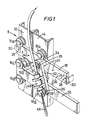
- the apparatus 8 has a frame which comprises two vertical channel members l2, l4 each of which supports four rollers l6 a , l6 b , l6 c , l6 d .
- a first support means comprising a first bar l8 is disposed between the rollers l6 a and l6 b whilst a second support means comprising a second bar 20 is disposed between the rollers l6 c and l6 d .
- Each roller l6 a , l6 b , l6 c , l6 d is provided with flanges 22 ( Figure 3) which guide their associated bars l8 and 20.
- the first bar l8 and second bar 20 are each prvided with a series of holes 24 which can be utilized to receive and hold weights to effect changes in the frequency of the oscillating action.
- a weight 26 is shown mounted on first bar l8.
- the holes 24 can also be utilized to receive and hold optional abutment members to limit the travel of the first bar l8 and the second bar 20.
- abutment member 30 is shown mounted in end hole 28 on the right hand end of the second bar 20 whilst another form of abutment member 50 is shown mounted in the end holes 28 of the first bar l8.
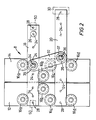
- a member 32 extends between the first bar l8 and the second bar 20.
- the member 32 is piovtably mounted on the first bar l8 via a pin 34 which passes through a hole in the upper portion of the member 32 and is secured fast in the first bar l8. Washers 35 are provided to either side of the member 32 as shown in Figure 4.
- the member 32 is also pivotably mounted on the second bar 20 via a pin 36. However, the lower portion of the member 32 is provided with a slot 37.
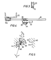
- a spray 46 of fluid is discharged from a nozzle 48 secured to the member 32.
- the spray 46 makes an angle ⁇ with respect to the vertical and consequently there is a reaction force F having a horizontal component Fx which urges the first bar l8 and the second bar l8 to the right as viewed in Figure 5.
- the first bar l8 When the first bar l8 reaches the rightmost limit of its travel ( Figure 6) it abuts the upper portion 42 of the housing 40. However, the second bar 20 continues to move under the influence of the spray 46. As the second bar 20 moves relative to the first bar l8 the angle decreases to 0°. At this point the horizontal component Fx of the reaction force F is zero. However, the inertia of the second bar 20 carries it to the position shown in Figure 7 where the second bar 20 abuts the lower portion 44 of the hpusing 40. The thrust of the spray 46 then drives the first bar l8 and the second bar 20 to the left as viewed in Figure 7 until it reaches the position shown in Figure 8 where the first bar l8 abut the upper portion 42 of the housing 40. As before, the second bar 20 continues moving to the left until it abuts the lower portion 44 of the housing 40. The cycle is then repeated.
- housing 40 can be replaced by stops on the first bar such as abutment member 50. Stops such as abutment member 30 on the second bar 20 are optional since the overall movement of the second bar 20 with respect to the first bar l8 is limited by the member 32 and the slot 37.
Landscapes
- Catching Or Destruction (AREA)
Applications Claiming Priority (2)
| Application Number | Priority Date | Filing Date | Title |
|---|---|---|---|
| US79597085A | 1985-11-07 | 1985-11-07 | |
| US795970 | 1985-11-07 |
Publications (3)
| Publication Number | Publication Date |
|---|---|
| EP0223528A2 true EP0223528A2 (fr) | 1987-05-27 |
| EP0223528A3 EP0223528A3 (en) | 1987-10-07 |
| EP0223528B1 EP0223528B1 (fr) | 1989-11-08 |
Family
ID=25166914
Family Applications (1)
| Application Number | Title | Priority Date | Filing Date |
|---|---|---|---|
| EP19860308716 Expired EP0223528B1 (fr) | 1985-11-07 | 1986-11-07 | Pulvérisateur oscillant |
Country Status (2)
| Country | Link |
|---|---|
| EP (1) | EP0223528B1 (fr) |
| DE (1) | DE3666784D1 (fr) |
Cited By (6)
| Publication number | Priority date | Publication date | Assignee | Title |
|---|---|---|---|---|
| DE3823138A1 (de) * | 1988-07-05 | 1990-04-19 | Mannesmann Ag | Einrichtung fuer das semikontinuierliche spruehkompaktieren |
| US9885194B1 (en) | 2017-05-11 | 2018-02-06 | Hayward Industries, Inc. | Pool cleaner impeller subassembly |
| US9885196B2 (en) | 2015-01-26 | 2018-02-06 | Hayward Industries, Inc. | Pool cleaner power coupling |
| US9896858B1 (en) | 2017-05-11 | 2018-02-20 | Hayward Industries, Inc. | Hydrocyclonic pool cleaner |
| US9909333B2 (en) | 2015-01-26 | 2018-03-06 | Hayward Industries, Inc. | Swimming pool cleaner with hydrocyclonic particle separator and/or six-roller drive system |
| US10156083B2 (en) | 2017-05-11 | 2018-12-18 | Hayward Industries, Inc. | Pool cleaner power coupling |
Family Cites Families (2)
| Publication number | Priority date | Publication date | Assignee | Title |
|---|---|---|---|---|
| US3424442A (en) * | 1966-09-06 | 1969-01-28 | Acme Ind Inc | Cooling tower water distributor |
| FR2265337A1 (en) * | 1974-03-28 | 1975-10-24 | Landot Jean | Machine for washing crockery, utensils - has upper and lower spray heads on carriage and rising water balloon |
-
1986
- 1986-11-07 EP EP19860308716 patent/EP0223528B1/fr not_active Expired
- 1986-11-07 DE DE8686308716T patent/DE3666784D1/de not_active Expired
Cited By (11)
| Publication number | Priority date | Publication date | Assignee | Title |
|---|---|---|---|---|
| DE3823138A1 (de) * | 1988-07-05 | 1990-04-19 | Mannesmann Ag | Einrichtung fuer das semikontinuierliche spruehkompaktieren |
| US9885196B2 (en) | 2015-01-26 | 2018-02-06 | Hayward Industries, Inc. | Pool cleaner power coupling |
| US9909333B2 (en) | 2015-01-26 | 2018-03-06 | Hayward Industries, Inc. | Swimming pool cleaner with hydrocyclonic particle separator and/or six-roller drive system |
| US10557278B2 (en) | 2015-01-26 | 2020-02-11 | Hayward Industries, Inc. | Pool cleaner with cyclonic flow |
| US11236523B2 (en) | 2015-01-26 | 2022-02-01 | Hayward Industries, Inc. | Pool cleaner with cyclonic flow |
| US12065854B2 (en) | 2015-01-26 | 2024-08-20 | Hayward Industries, Inc. | Pool cleaner with cyclonic flow |
| US9885194B1 (en) | 2017-05-11 | 2018-02-06 | Hayward Industries, Inc. | Pool cleaner impeller subassembly |
| US9896858B1 (en) | 2017-05-11 | 2018-02-20 | Hayward Industries, Inc. | Hydrocyclonic pool cleaner |
| US10156083B2 (en) | 2017-05-11 | 2018-12-18 | Hayward Industries, Inc. | Pool cleaner power coupling |
| US10253517B2 (en) | 2017-05-11 | 2019-04-09 | Hayward Industries, Inc. | Hydrocyclonic pool cleaner |
| US10767382B2 (en) | 2017-05-11 | 2020-09-08 | Hayward Industries, Inc. | Pool cleaner impeller subassembly |
Also Published As
| Publication number | Publication date |
|---|---|
| EP0223528A3 (en) | 1987-10-07 |
| DE3666784D1 (en) | 1989-12-14 |
| EP0223528B1 (fr) | 1989-11-08 |
Similar Documents
| Publication | Publication Date | Title |
|---|---|---|
| CA2050263A1 (fr) | Structures permettant de maintenir en position des boitiers d'appareils electroniques | |
| DE3160611D1 (en) | Device for fixing a wall cabinet to a wall | |
| US4993542A (en) | Belt conveyor | |
| HK184495A (en) | Apparatus for mounting panel member | |
| EP0223528A2 (fr) | Pulvérisateur oscillant | |
| IT1184441B (it) | Metodo per il funzionamento risonante selettivo,a piu' cicli,di un apparato a getto di inchiostro,per il controllo delle dimensioni di un punto | |
| US5535091A (en) | Keyboard structure for mobile computers | |
| GB1148166A (en) | Pallet tiering frame | |
| US5099677A (en) | Pipe expanding apparatus | |
| EP0083500B1 (fr) | Transporteur à ligne sans fin | |
| FR2677597B1 (fr) | Dispositif d'ejection de liquide de lave-galce monte sur un balai d'essuie-glace. | |
| IT9041560A1 (it) | Supporto per tende, particolarmente del tipo a pannelli orientabili | |
| US12419417B2 (en) | Slide rail assembly | |
| US4728041A (en) | Fluid spray apparatus | |
| KR930021287A (ko) | 휨가공장치 | |
| KR930017771A (ko) | 모터스쿠터(motor-scooter)의 후방 짐 래크(rack)와 거기에 용기요소를 고정하는 방법 | |
| EP0387238A3 (fr) | Dispositif pour le déplacement longitudinal d'une bande flexible se trouvant en face d'un instrument se déplaçant transversalement | |
| KR890003526A (ko) | 푸레스의 소재 자동공급장치 | |
| EP0256948B1 (fr) | Appareil pour souder du type fontaine | |
| CN110117860B (zh) | 改进的织带机滑动结构 | |
| US3073187A (en) | Apparatus for drilling holes in ladder stringers | |
| CN219362437U (zh) | 推进装置 | |
| CN214411494U (zh) | 一种宽带定向天线底架 | |
| SU927502A2 (ru) | Форма дл изготовлени строительных изделий | |
| IT1176686B (it) | Seghetto alternativo, provvisto di lama verticale comandata da braccetti oscillanti interconnessi, mossi da un meccanismo ad eccentrico |
Legal Events
| Date | Code | Title | Description |
|---|---|---|---|
| PUAI | Public reference made under article 153(3) epc to a published international application that has entered the european phase |
Free format text: ORIGINAL CODE: 0009012 |
|
| AK | Designated contracting states |
Kind code of ref document: A2 Designated state(s): DE GB IT NL |
|
| PUAL | Search report despatched |
Free format text: ORIGINAL CODE: 0009013 |
|
| AK | Designated contracting states |
Kind code of ref document: A3 Designated state(s): DE GB IT NL |
|
| 17P | Request for examination filed |
Effective date: 19880517 |
|
| 17Q | First examination report despatched |
Effective date: 19890109 |
|
| ITF | It: translation for a ep patent filed | ||
| GRAA | (expected) grant |
Free format text: ORIGINAL CODE: 0009210 |
|
| AK | Designated contracting states |
Kind code of ref document: B1 Designated state(s): DE GB IT NL |
|
| REF | Corresponds to: |
Ref document number: 3666784 Country of ref document: DE Date of ref document: 19891214 |
|
| PLBE | No opposition filed within time limit |
Free format text: ORIGINAL CODE: 0009261 |
|
| STAA | Information on the status of an ep patent application or granted ep patent |
Free format text: STATUS: NO OPPOSITION FILED WITHIN TIME LIMIT |
|
| PGFP | Annual fee paid to national office [announced via postgrant information from national office to epo] |
Ref country code: GB Payment date: 19900907 Year of fee payment: 5 |
|
| PGFP | Annual fee paid to national office [announced via postgrant information from national office to epo] |
Ref country code: DE Payment date: 19900924 Year of fee payment: 5 |
|
| 26N | No opposition filed | ||
| ITTA | It: last paid annual fee | ||
| PGFP | Annual fee paid to national office [announced via postgrant information from national office to epo] |
Ref country code: NL Payment date: 19901130 Year of fee payment: 5 |
|
| ITPR | It: changes in ownership of a european patent |
Owner name: CESSIONE;BUTTERWORTH JETTING SYSTEMS INC. |
|
| NLS | Nl: assignments of ep-patents |
Owner name: BUTTERWORTH JETTING SYSTEMS, INC. TE HOUSTON, TEXA |
|
| PG25 | Lapsed in a contracting state [announced via postgrant information from national office to epo] |
Ref country code: GB Effective date: 19911107 |
|
| REG | Reference to a national code |
Ref country code: GB Ref legal event code: 732 |
|
| PG25 | Lapsed in a contracting state [announced via postgrant information from national office to epo] |
Ref country code: NL Effective date: 19920601 |
|
| GBPC | Gb: european patent ceased through non-payment of renewal fee | ||
| NLV4 | Nl: lapsed or anulled due to non-payment of the annual fee | ||
| PG25 | Lapsed in a contracting state [announced via postgrant information from national office to epo] |
Ref country code: DE Effective date: 19920801 |
|
| PG25 | Lapsed in a contracting state [announced via postgrant information from national office to epo] |
Ref country code: IT Free format text: LAPSE BECAUSE OF NON-PAYMENT OF DUE FEES;WARNING: LAPSES OF ITALIAN PATENTS WITH EFFECTIVE DATE BEFORE 2007 MAY HAVE OCCURRED AT ANY TIME BEFORE 2007. THE CORRECT EFFECTIVE DATE MAY BE DIFFERENT FROM THE ONE RECORDED. Effective date: 20051107 |