EP0223552B1 - Vanne de circulation pour fond de puits et procédé pour son fonctionnement - Google Patents
Vanne de circulation pour fond de puits et procédé pour son fonctionnement Download PDFInfo
- Publication number
- EP0223552B1 EP0223552B1 EP86308808A EP86308808A EP0223552B1 EP 0223552 B1 EP0223552 B1 EP 0223552B1 EP 86308808 A EP86308808 A EP 86308808A EP 86308808 A EP86308808 A EP 86308808A EP 0223552 B1 EP0223552 B1 EP 0223552B1
- Authority
- EP
- European Patent Office
- Prior art keywords
- valve
- mandrel
- pressure
- valve mandrel
- housing
- Prior art date
- Legal status (The legal status is an assumption and is not a legal conclusion. Google has not performed a legal analysis and makes no representation as to the accuracy of the status listed.)
- Expired - Lifetime
Links
Images


Classifications
-
- E—FIXED CONSTRUCTIONS
- E21—EARTH OR ROCK DRILLING; MINING
- E21B—EARTH OR ROCK DRILLING; OBTAINING OIL, GAS, WATER, SOLUBLE OR MELTABLE MATERIALS OR A SLURRY OF MINERALS FROM WELLS
- E21B23/00—Apparatus for displacing, setting, locking, releasing or removing tools, packers or the like in boreholes or wells
- E21B23/004—Indexing systems for guiding relative movement between telescoping parts of downhole tools
- E21B23/006—"J-slot" systems, i.e. lug and slot indexing mechanisms
-
- E—FIXED CONSTRUCTIONS
- E21—EARTH OR ROCK DRILLING; MINING
- E21B—EARTH OR ROCK DRILLING; OBTAINING OIL, GAS, WATER, SOLUBLE OR MELTABLE MATERIALS OR A SLURRY OF MINERALS FROM WELLS
- E21B34/00—Valve arrangements for boreholes or wells
- E21B34/06—Valve arrangements for boreholes or wells in wells
- E21B34/10—Valve arrangements for boreholes or wells in wells operated by control fluid supplied from outside the borehole
-
- E—FIXED CONSTRUCTIONS
- E21—EARTH OR ROCK DRILLING; MINING
- E21B—EARTH OR ROCK DRILLING; OBTAINING OIL, GAS, WATER, SOLUBLE OR MELTABLE MATERIALS OR A SLURRY OF MINERALS FROM WELLS
- E21B49/00—Testing the nature of borehole walls; Formation testing; Methods or apparatus for obtaining samples of soil or well fluids, specially adapted to earth drilling or wells
- E21B49/001—Testing the nature of borehole walls; Formation testing; Methods or apparatus for obtaining samples of soil or well fluids, specially adapted to earth drilling or wells specially adapted for underwater installations
Definitions
- the present invention relates generally to apparatus and methods for testing an oil well, and more particularly, but not by way of limitation, to a circulation valve which may be placed in a circulating condition or closed in response to annulus and drill string pressure.
- the prior art includes a number of sliding sleeve type circulation valves which are opened in response to annulus pressure. Typically once open, a prior art valve remains locked in an open condition. Examples of such are described in U.S.-A- 4,064,937 and 3,970,147. There are however exceptions.
- U.S.-A- 4,452,313 discloses a circulation valve which may be initially opened by pressurizing the well annulus and which may subsequently be re-closed and reopened by setting down weight on the circulation valve or picking up weight from the circulation valve.
- a multi-mode testing tool which includes a circulation valve comprising a cylindrical housing having an open longitudinal passageway therethrough and a circulation port disposed through a wall thereof, and a valve mandrel slidably received in the housing.
- the circulation port is opened (to permit fluid flow between the annulus and the string) and closed in response to pressure changes.
- a circulation valve adapted to be suspended in a well bore on a pipe string
- a cylindrical housing having an open longitudinal passageway therethrough and a circulation port disposed through a wall thereof
- a valve mandrel slidably received in said housing, said circulation valve being characterised in that said valve mandrel is movable between a position in which fluid may flow through said circulation port only from the well bore annulus to the pipe string, and a position in which fluid may flow through said circulation port only from the pipe string to the well bore annulus, said valve mandrel positions being axially spaced from one another; and wherein said circulation valve further includes piston means operatively connected to said valve mandrel, said piston means being exposed to pressure interior and exterior of said housing for axially moving said valve mandrel to a selected one of said positions responsive to pressure changes across said housing.
- the circulation valve of the present invention may be initially placed in condition for reverse circulation by alternately pumping down the drill string and annulus a predetermined number of times and/or pumping down and releasing pressure in the drill string. Thereafter, pumping down of the drill string places the valve in condition for spotting fluids in the well bore through the valve after which pumping down the annulus closes the valve.
- pumping down the annulus or drill string, as used herein, is employed to describe the increasing of pressure and/or flow in the annulus or drill string as the case may be.
- the circulation valve of the invention can permit selective reverse circulating and spotting fluids down the well, while at the same time permitting application of drill string and annulus pressure to pump fluids and actuate other tools without unintentionally opening or closing the circulation valve.
- drilling fluid a fluid known as drilling fluid or drilling mud.
- drilling fluid a fluid which may be found there.
- the drilling mud is weighted with various additives so that the hydrostatic pressure of the mud at the formation depth is sufficient to maintain the formation fluid within the formation without allowing it to escape into the borehole.
- a testing string When it is desired to test the production capabilities of the formation, a testing string is lowered into the borehole to the formation depth and the formation fluid is allowed to flow into the string in a controlled testing program. Lower pressure is maintained in the interior of the testing string as it is lowered into the borehole. This is usually done by keeping a valve in the closed position near the lower end of the testing string. When the testing depth is reached, a packer is set to seal the borehole thus closing in the formation from the hydrostatic pressure of the drilling fluid in the well annulus. Alternatively, the string may be stabbed into a previously set production packer.
- the testing program includes periods of formation flow and periods when the formation is closed in. Pressure recordings are taken throughout the program for later analysis to determine the production capability of the formation. If desired, a sample of the formation fluid may be caught in a suitable sample chamber.
- a circulation valve in the test string is opened, formation fluid in the testing string is circulated out, the packer is released, and the testing string is withdrawn.
- tester valves located at the formation depth as described. These methods include string rotation, string reciprocation, and annulus pressure changes.
- Particularly advantageous tester valves are those shown in U.S. Patent No's. 3,856,085 to Holden, et al., 4,422,506 and 4,429,748 to Beck, and 4,444,268 and 4,448,254 to Barrington. These valves operate responsive to pressure changes in the annulus and provide a full opening flow passage through the tester valve apparatus.
- FIG. 1 A typical arrangement for conducting a drill stem test offshore is shown in Fig. 1. Such an arrangement would include a floating work station 1 stationed over a submerged work site 2.
- the well comprises a well bore 3 typically lined with a casing string 4 extending from the work site 2 to a submerged formation 5.
- the casing string 4 includes a plurality of perforations at its lower end which provide communication between the formation 5 and the interior of the well bore 6.
- a marine conductor 8 extends from the well head installation to the floating work station 1.
- the floating work station includes a work deck 9 which supports a derrick 12.
- the derrick 12 supports a hoisting means 11.
- a well head closure 13 is provided at the upper end of marine conductor B. The well head closure 13 allows for lowering into the marine conductor and into the well bore 3 a formation testing string 10 which is raised and lowered in the well by hoisting means 11.
- a supply conduit 14 is provided which extends from a hydraulic pump 15 on the deck 9 of the floating station 1 and extends to the well head installation 7 at a point below the blowout preventors to allow the pressurizing of the well annulus 16 surrounding the test string 10.
- the testing string includes an upper circuit string portion 17 extending from the work site 1 to the well head installation 7.
- a hydraulically operated conduit string test tree 18 is located at the end of the upper conduit string 17 and is landed in the well head installation 7 to thus support the lower portion of the formation testing string.
- the lower portion of the formation testing string extends from the test tree 18 to the formation 5.
- a packer mechanism 27 isolates the formation 5 from fluids in the well annulus 16.
- a perforated tail piece 28 is provided at the lower end of the testing string 10 to allow fluid communication between the formation 5 and the interior of the tubular formation testing string 10.
- the lower portion of the formation testing string 10 further includes intermediate conduit portion 19 and torque transmitting pressure and volume balanced slip joint means 20.
- An intermediate conduit portion 21 is provided for imparting packer setting weight to the packer mechanism 27 at the lower end of the string.
- a conventional circulating valve 22 which may be opened by rotation or reciprocation of the testing string or a combination of both or by the dropping of a weighted bar in the interior of the testing string 10.
- This circulation valve is provided as a back-up means to provide for fluid communication in the event that the circulation valve of the present apparatus should fail to open properly.
- a tester valve 25 which is preferably a tester valve of the annulus pressure operated type such as those disclosed in U.S. Patent No's. 3,856,085; 4,422,506; 4,429,748; 4,444,268; and 4,448,254.
- a tool 201 which incorporates the apparatus of the present invention.
- a pressure recording device 26 is located below the tester valve 25.
- the pressure recording device 26 is preferably one which provides a full opening passageway through the center of the pressure recorder to provide a full opening passageway through the entire length of the formation testing string.
- testing string 10 It may be desirable to add additional formation testing apparatus in the testing string 10. For instance, where it is feared that the testing string 10 may become stuck in the borehole 3 it is desirable to add a jar mechanism between the pressure recorder 26 and the packer assembly 27.
- the jar mechanism is used to impart blows to the testing string to assist in jarring a stuck testing string loose from the borehole in the event that the testing string should become stuck.
- a safety joint between the jar and the packer mechanism 27. Such a safety joint would allow for the testing string 10 to be disconnected from the packer assembly 27 in the event that the jarring mechanism was unable to free a stuck formation testing string.
- the location of the pressure recording device may be varied as desired.
- the pressure recorder may be located below the perforated tail piece 28 in a suitable pressure recorder anchor shoe running case.
- a second pressure recorder may be run immediately above the tester valve 25 to provide further data to assist in evaluating the well.
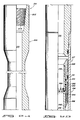
- Tool 201 includes a cylindrical outer housing, generally designated by the numeral 200, having an upper housing adapter 202 which includes threads 204 for attaching tool 201 to the portion of testing string 10 located above tool 201.
- a lower housing adapter 206 which includes an externally threaded portion 208 for connection of tool 201 to a portion of test string 10 located below the tool.
- Housing 200 further includes an upper housing section 210, an intermediate housing section 212 and a lower housing section 214.
- the interior of the components making up housing 200 forms a fluid flow passageway 216 axially through tool 201.
- the various housing sections and the upper and lower adapter are threadably connected to one another via threaded connections as shown in the drawing with each such threaded connection being sealed with O-rings as shown.
- a circulation valve Indicated generally at 217 in Figures 2B and 2C is a circulation valve.
- a generally tubular valve mandrel 218 is closely received within upper housing section 210 and is sealingly engaged therewith via O-rings 220, 222, 224, and 226.
- An upper valve sleeve 228 is closely received within upper housing section 210 and is threadably engaged via threads 230 to the upper end of valve mandrel 218.
- An O-ring 231 sealingly engages the radially outer surface of upper valve sleeve 228 to the radially inner surface of upper housing section 210.
- a lower valve sleeve 234, in Figure 2C, is threadably engaged via threads 236 to the lower end of valve mandrel 218 and is sealingly engaged thereto via O-ring seal 238.
- Valve mandrel 218 includes a lower check valve indicated generally at 240. Included therein is a resilient valve portion 242, such comprising an annular lip having a radially outer surface 244 which bears against the radially inner surface of valve mandrel 218. Valve portion 242 is inserted over and carried by a valve portion carrier 246. Carrier 246 supports valve portion 242 to create an annular space 248 between the radially outer surface of the valve portion and the radially inner surface of valve mandrel 218. A plurality of bores, one of which is bore 250, are formed through mandrel 210 about the circumference thereof and permit fluid communication between the exterior of the mandrel and space 248. Upper housing section 210 includes a circulation port 252 to permit fluid communication between the interior and exterior of upper housing section 210.
- Valve carrier 246 is received between the upper end of lower valve sleeve 234 and a bevel 254 formed on the radially inner surface of valve mandrel 218 and is thus restrained from axial movement relative to the valve mandrel.
- an upper check valve is indicated generally at 256. Included therein is a resilient valve portion 258 having an annular lip which has a radially inner surface 260 that is sealingly engaged against the radially outer surface of valve mandrel 218 about its circumference. Resilient valve portion 258 is carried by a valve portion carrier 262. A space 264 is formed between the radially inner surface of resilient valve portion 258 and the radially outer surface of the valve mandrel.
- a plurality of bores indicated generally at 266 provide fluid communication between the interior of the valve mandrel 218 and space 264 about the circumference of the valve mandrel.
- Valve carrier 262 is received between the lower end of upper valve sleeve 228 and a bevel 268 formed on the radially outer surface of valve mandrel 218 about its circumference and is thus restrained from axial movement relative to the valve mandrel.
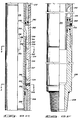
- a piston mandrel 270 in Figure 2C, 2D, and 2E has an upper end threadably secured via threads 272 to the lower end of lower valve sleeve 234.
- the radially outer surface of piston mandrel 270 and the radially inner surfaces of upper housing section 210 and intermediate housing section 212 define an upper annular space 274 which is in communication with the exterior of the tool via a power port 276.
- O-rings 278, 280 seal the radially inner and outer surfaces of intermediate housing section 212 and define the lower end of annular space 274.
- O-rings 278, 280 define the upper end of a lower annular space 282 which has as its outer boundary the radially inner surface of lower housing section 214.
- the radially inner boundry of space 282 is defined by the outer surface of piston mandrel 270 and the outer surface of a lower piston mandrel 286 which is threadably secured to the lower end of piston mandrel 270 via threads 288.
- annular floating piston 290 Disposed at the lower end of annular space 282 is an annular floating piston 290. Piston 290 is sealingly and slidingly received between the radially outer surface of the lower piston mandrel and the radially inner surface of lower housing section 214. Lower annular space 282 is filled with oil to provide lubrication to moving parts, to be hereinafter more fully described, contained within space 282.
- the lower side of floating piston 290 is in fluid communication with the exterior of tool 201 via a port 293 formed through the wall of lower housing section 214.
- the floating piston prevents drilling mud and other contaminates in the well bore from becoming mixed with the oil contained in annular space 282 above the floating piston.
- an indexing sleeve 292 is closely received over piston mandrel 270 and is restrained from axial movement therealong by a downward facing shoulder 294 formed on mandrel 270 and the upper surface of lower piston mandrel 286.
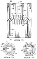
- An outer cylindrical surface 296 on indexing sleeve 292 concludes a continuous slot or groove, such being indicated generally at 298.
- Groove 298 includes a repeating zig-zag portion 300 which rotates sleeve 292 counter-clockwise, as viewed from above, upon reciprocation of piston mandrel 270 relative to housing 200.
- Groove 298 further includes first and second vertical groove portions 302, 304.
- Each of groove portions 302, 304 includes an upper and lower leg, like upper leg 305 and lower leg 307 in groove 302.
- Connecting groove portions 306, 308 connect repeating zig-zag portion 300 with vertical groove portions 302, 304.
- Zig-zag portion 300 includes a first leg 310 having an upper surface 312 and a lower surface 314.
- Each of the other legs in zig-zag portion 300 include similar upper and lower surfaces.
- each of vertical grooves 302, 304 include upper and lower surfaces like upper surface 316 and lower surface 318 in groove portion 302.
- a ball 320 is biased into groove portion 302 and more particularly into the lower portion of the groove as viewed in both Figures 5 and 2E.
- ball 320 is mounted on the radially inner surface of an annular shoulder 324 which is formed on the radially inner surface of lower housing section 214.
- annular shoulder 324 is formed on the radially inner surface of lower housing section 214.
- An annular shoulder 322 is formed on the radially inner surface of lower housing section 214 about its circumference.
- Annular shoulder 324 includes a similar pair of opposed slots 330, 332 with slot 330 being axially aligned with slot 326 and slot 332 being axially aligned with slot 328.
- Indexing sleeve 292 includes a pair of opposed load lugs 334, 336, such being viewable in Figure 4.
- opposing lugs 334, 336 are received within slots 326, 328, respectively.
- Load lug 336 is viewable in Figure 5 and is shown in dot-dash lines in Figure 2E, such indicating where load lug 336 is positioned on the rear side of index sleeve 292, with lug 334 being half cut away in the quarter section and half obscured by lower housing section 214.
- Load lug 336 includes an upper abutment surface 338 and a lower abutment surface 340.
- Abutment surfaces 336, 340 comprise the upper and lower surfaces, respectively; of the load lug which extends outwardly from the radially outer surface of indexing sleeve 292.
- annular shoulder 322 includes upper and lower abutment surfaces 342, 344, respectively.
- shoulder 324 includes upper and lower abutment surfaces 346, 348, respectively.
- the upper surface of lower piston mandrel 286 comprises an abutment surface 350 with surface 348 being abutted against surface 350 in the view of Figure 2E.
- Additional abutment surfaces are seen in Figures 2C and 2D and include surface 352 on the lower end of lower valve sleeve 234 and surface 354 on the upper end of intermediate housing section 212. As will be explained hereinafter, the various abutment surfaces interact with one another to limit the axial movement of valve mandrel 218 and thereby place the valve in a closed condition, in a condition for circulation of fluids, or in a condition for reverse circulation of fluids.
- mandrel 270 is axially reciprocated relative to housing 200 in order to place ball 320 in the lower end of leg 310 as shown in dashed lines in Figure 5.
- ball 320 is adjacent lower surface 314.
- abutment surface 338 of load lug 336 and the upper surface of the opposing load lug are abutted against abutment surface 344 on the underside of annular shoulder 322.
- surfaces 338, 344 are so abutted, ball 320 is not abutted against surface 314 on the lower portion of leg 310 but rather is positioned just adjacent thereto.
- valve mandrel 218 When power piston 270 is positioned with ball 320 in leg 310 as described above, valve mandrel 218 is positioned over circulation port 252, in Figure 2C, between O-rings 222, 224. Thus, fluid communication between passageway 216 and the exterior of tool 201 is prevented.
- the tool With the tool configured as described above, it is assembled into the drill string and lowered into the well bore as shown in Figure 1. With this arrangement, fluids may be pumped into the drill string on which tool 201 is suspended for purposes of fracturing or injecting acid into the formation. Also, the annulus between tool 201 and the well bore may be pressurized in order to operate different tools in the drill string testing arrangement.
- passageway 216 is pressurized thus forcing power mandrel 270 downwardly until ball 320 is received in the upper portion of leg 310, as shown in dashed lines in Figure 5, adjacent surface 312.
- the power mandrel is urged downwardly under such pressurization due to the action of an annular piston which is defined by an outer diameter at seal 238 in Figure 2C and by an inner diameter at O-ring 278 in Figure 2E.
- Fluid pressure in passageway 216 acts across the difference in area between seal 238 and O-ring 278 to urge power mandrel 270 downwardly.
- ball 320 moves from the lower portion of log 310 to the upper portion of leg 310 adjacent upper surface 312.
- annulus pressure may be applied or drill string pressure released to urge piston mandrel 270 upwardly thereby causing ball 320 to enter connecting portion 306 and thereafter lower leg 307 as the piston mandrel continues its upward movement.
- Abutment surface 338 does not strike abutment surface 344 on the lower surface of shoulder 322 as during piston mandrel reciprocation when ball 320 is received in zig-zag portion 300. This is because load lugs 334, 336 are received within slots 326, 328, in Figure 4, and thus permit movement of ball 320 down lower leg 307.
- abutment surface 348 on the lower side of shoulder 324 abuts against surface 350 on the upper side of lower piston mandrel 286 thus stopping further mandrel movement and preventing ball 320 from absorbing a significant axial load.
- valve mandrel 218 When ball 320 is in the lower end of leg 307 as shown in the solid-line view of Figure 5 and Figure 2E, valve mandrel 218 is positioned relative to port 252 as shown in Figure 2C. When so positioned fluid may be reverse circulated through port 252, bore 250 (and the other bores about the perimeter of valve mandrel 218 adjacent bore 250), into annular space 248 on the radially inner surface of valve mandrel 218 and into passageway 216.
- valve mandrel 218 when valve mandrel 218 is in the configuration of 2C, the well may be reverse circulated but, because of the action of resilient valve portion 242, the well may not be circulated from the drill string into the annulus.
- pressure in passageway 216 is greater than the pressure in the annulus, surface 242 sealingly engages the radially inner surface of the valve mandrel thus preventing flow between passageway 216 and the annulus.
- passageway 216 may be pressurized (by pumping down the drill string) thus driving piston mandrel 270 downwardly and moving ball 320 upwardly in leg 307 and into leg 305 until the ball is adjacent surface 316.
- surface 352 on the lower end of lower valve sleeve 234 abuts against surface 354 on the upper end of intermediate housing section 212 thus stopping further downward movement of piston mandrel and preventing ball 320 from bearing significant forces as a result of impact with surface 316.
- valve mandrel 218 When the piston mandrel is in its lowermost condition as just previously described, O-ring 220 on valve mandrel 218 is beneath circulating port 252 thus permitting circulation from passageway 216 into the well bore as follows.
- pressure in passageway 216 increases above that in the annulus, fluid flows through bores 266 into annular space 264, between surface 260 and the radially outer surface of valve mandrel 218, and through port 252 into the annulus.
- the annulus is pressurized thus driving piston mandrel 270 upwardly and causing ball 320 to move down leg 305 and into the zig-zag portion (not shown) on surface 296 opposite zig-zag portion 300.
- the tool is again in condition to permit repeated alternate applications of annulus and drill string pressure or applications and releases of drill string pressure without shifting the tool into condition for circulation or for reverse circulation. It can be seen that, in the tool of the preferred embodiment, five such alternate applications of annulus and drill string pressure or applications and releases of drill string pressure may occur before the tool is again placed in condition for reverse circulation. Thereafter, application of drill string pressure places the tool in condition for circulation to permit, for example, the spotting of fluids into the well bore adjacent tool 201. It will be apparent to one skilled in the art that more or fewer than five cycles may readily be employed by changing the slot.
- tool 201 permits alternate pumping of fluids into the formation and operation of various tools by pressurizing the well bore without placing the tool in condition for circulation or reverse circulation until the annulus and drill string have been alternately pressurized a predetermined number of times.
- Such a tool permits reversing fluids out of the drill string and thereafter spotting fluids, for example nitrogen, into the well bore adjacent tool 201. Thereafter, annulus pressure can be increased to actuate other valves and/or tools in the well bore without compressing the nitrogen in the drill string.
- tool 201 permits selectively reverse circulating and spotting fluids down the well while at the same time permitting application of drill string and annulus pressures to pump fluids and actuate other tools without unintentionally opening or closing the circulation valve.
Landscapes
- Life Sciences & Earth Sciences (AREA)
- Engineering & Computer Science (AREA)
- Geology (AREA)
- Mining & Mineral Resources (AREA)
- Physics & Mathematics (AREA)
- Environmental & Geological Engineering (AREA)
- Fluid Mechanics (AREA)
- General Life Sciences & Earth Sciences (AREA)
- Geochemistry & Mineralogy (AREA)
- Check Valves (AREA)
- Sliding Valves (AREA)
- Earth Drilling (AREA)
Claims (10)
- Vanne de circulation destinée à être suspendue dans un sondage à un train de tiges, comprenant un boîtier cylindrique (200) ayant un passage longitudinal ouvert (216) qui le traverse et un orifice de circulation (252) traversant sa paroi, et un mandrin (218) de vanne qui peut coulisser dans le boîtier, la vanne de circulation étant caractérisée en ce que le mandrin de vanne est mobile entre une position dans laquelle le fluide peut circuler par l'orifice de circulation uniquement de l'anneau du sondage vers le train de tiges, et une position dans laquelle le fluide peut circuler par l'orifice de circulation uniquement du train de tiges vers l'anneau du sondage, les positions du mandrin de vanne étant espacées axialement l'une de l'autre, et dans laquelle la vanne de circulation comporte en outre un piston (270) raccordé au mandrin de vanne, le piston étant exposé à la pression à l'intérieur et à l'extérieur du boîtier et étant destiné à déplacer axialement le mandrin de vanne vers l'une des positions choisies en fonction des variations de pression de part et d'autre du boîtier.
- Vanne selon la revendication 1, dans laquelle le mandrin de vanne est aussi mobile vers une position dans laquelle il empêche la circulation du fluide par l'orifice de circulation dans les deux sens.
- Vanne selon la revendication 1 ou 2, qui comporte en outre un dispositif (292, 322, 324) destiné à limiter le déplacement axial du mandrin de vanne, le dispositif de limitation comportant de préférence un ensemble à gorge (300) et patte, la gorge (300) ayant de préférence un dessin dont la construction et la disposition permettent la mise sous pression relative en alternance de l'intérieur et de l'extérieur du boîtier un nombre prédéterminé de fois lorsque le mandrin de vanne est en position de fermeture de l'orifice avant que le mandrin de vanne ne puisse se déplacer vers l'une des autres positions.
- Vanne selon la revendication 1, dans laquelle le mandrin de vanne (218) est mobile axialement par coulissement entre une première position dans laquelle il ferme l'orifice de circulation et une seconde position dans laquelle le fluide peut circuler par cet orifice, et dans laquelle la vanne comporte un piston annulaire (270) logé dans le boîtier et raccordé au mandrin de vanne pendant le fonctionnement, le piston ayant un premier côté soumis à une pression régnant dans l'anneau de sondage et un second côté soumis à une pression régnant dans le train de tiges, le piston déplaçant le mandrin de vanne vers l'une de ses positions lorsque la pression du premier côté dépasse la pression du second côté et déplaçant le mandrin vers l'autre desdites positions lorsque la pression du second côté dépasse la pression du premier côté, et un dispositif (292, 320, 322, 324, 334, 336) destiné à empêcher le déplacement du mandrin de vanne de la première position jusqu'à ce que la pression de part et d'autre du piston dépasse en alternance la pression de l'autre côté un nombre prédéterminé de fois, le dispositif destiné à empêcher le déplacement comprenant de préférence un ensemble à gorge et patte.
- Vanne selon la revendication 4, dans laquelle le mandrin de vanne est mobile axialement vers une troisième position dans laquelle du fluide peut circuler par l'orifice.
- Vanne selon la revendication 5, dans laquelle le mandrin de vanne comporte un dispositif (242) destiné à empêcher la circulation du fluide du train de tiges vers l'anneau du sondage lorsque le mandrin est dans la seconde position, et un dispositif (220, 222, 224, 226) destiné à empêcher la circulation du fluide de l'anneau du sondage vers le train de tiges lorsque le mandrin de vanne est dans la troisième position, le mandrin de vanne comprenant de préférence un premier clapet de retenue (244) destiné à permettre la circulation du fluide dans un premier sens uniquement entre le train de tiges et l'anneau du sondage lorsque le mandrin de vanne est dans la seconde position, et de préférence aussi un second clapet de retenue (256) destiné à permettre la circulation du fluide uniquement du train de tiges vers l'anneau du sondage lorsque le mandrin de vanne est dans la troisième position.
- Vanne selon la revendication 6, dans laquelle le mandrin de vanne comporte un organe de forme générale tubulaire ayant un premier trou (250) et un second trou (266) décalés axialement l'un par rapport à l'autre, et le premier clapet de retenue est associé au premier trou et le second clapet de retenue est associé ou second trou.
- Procédé de commande d'une vanne de circulation (201), du type comprenant un mandrin de vanne (218) disposé afin qu'il puisse coulisser dans un boîtier cylindrique (200) et mobile entre une première position de fermeture d'un orifice de circulation (252) formé dans le boîtier et une seconde position dans laquelle le fluide peut circuler par l'orifice, le procédé comprenant les étapes suivantes : l'augmentation de la pression à l'extérieur du boîtier par rapport à l'intérieur de manière que le mandrin de vanne soit déplacé vers l'une des positions dans le boîtier cylindrique, la pression à l'extérieur du boîtier étant communiquée à un premier piston (234) du mandrin de vanne par un orifice moteur (276) formé dans une paroi du boîtier cylindrique, l'augmentation de la pression à l'intérieur du boîtier par rapport à la pression à l'extérieur de celui-ci de manière que le mandrin de vanne soit déplacé vers l'autre des positions dans le boîtier, le mandrin de vanne ayant un second piston (270) qui est exposé à la pression à l'intérieur du boîtier, et l'interdiction du déplacement du mandrin de vanne depuis la première position jusqu'à ce que la pression à l'intérieur du boîtier dépasse en alternance la pression à l'extérieur du boîtier un nombre prédéterminé de fois, caractérisé en ce qu'il comporte en outre une étape qui permet la circulation dans l'orifice dans un premier sens uniquement lorsque le mandrin de vanne est dans la seconde position.
- Procédé selon la revendication 8, qui comporte en outre les étapes suivantes : le déplacement du mandrin de vanne (218) vers une troisième position, et l'autorisation de la circulation dans l'orifice (252) dans l'autre sens uniquement lorsque le mandrin de vanne est dans la troisième position.
- Procédé selon la revendication 9, dans lequel l'étape de déplacement du mandrin de vanne (218) vers une troisième position comprend l'étape d'application de la pression du fluide à l'un des pistons (234, 270).
Applications Claiming Priority (2)
| Application Number | Priority Date | Filing Date | Title |
|---|---|---|---|
| US797375 | 1985-11-12 | ||
| US06/797,375 US4657082A (en) | 1985-11-12 | 1985-11-12 | Circulation valve and method for operating the same |
Publications (3)
| Publication Number | Publication Date |
|---|---|
| EP0223552A2 EP0223552A2 (fr) | 1987-05-27 |
| EP0223552A3 EP0223552A3 (en) | 1989-03-22 |
| EP0223552B1 true EP0223552B1 (fr) | 1992-01-15 |
Family
ID=25170665
Family Applications (1)
| Application Number | Title | Priority Date | Filing Date |
|---|---|---|---|
| EP86308808A Expired - Lifetime EP0223552B1 (fr) | 1985-11-12 | 1986-11-12 | Vanne de circulation pour fond de puits et procédé pour son fonctionnement |
Country Status (8)
| Country | Link |
|---|---|
| US (1) | US4657082A (fr) |
| EP (1) | EP0223552B1 (fr) |
| AU (1) | AU587654B2 (fr) |
| CA (1) | CA1287567C (fr) |
| DE (1) | DE3683457D1 (fr) |
| ES (1) | ES2027962T3 (fr) |
| NO (1) | NO864487L (fr) |
| SG (1) | SG33892G (fr) |
Families Citing this family (51)
| Publication number | Priority date | Publication date | Assignee | Title |
|---|---|---|---|---|
| US4823877A (en) * | 1985-08-14 | 1989-04-25 | Mcdaniel Robert J | Open hole pipe recovery circulation valve |
| US4657082A (en) * | 1985-11-12 | 1987-04-14 | Halliburton Company | Circulation valve and method for operating the same |
| EP0272080B1 (fr) * | 1986-12-18 | 1993-04-21 | Ingram Cactus Limited | Procédé et dispositif de cimentation et de nettoyage pour un puits |
| US4782897A (en) * | 1987-03-02 | 1988-11-08 | Halliburton Company | Multiple indexing J-slot for model E SRO valve |
| US4787447A (en) * | 1987-06-19 | 1988-11-29 | Halliburton Company | Well fluid modular sampling apparatus |
| US4878538A (en) * | 1987-06-19 | 1989-11-07 | Halliburton Company | Perforate, test and sample tool and method of use |
| US4817723A (en) * | 1987-07-27 | 1989-04-04 | Halliburton Company | Apparatus for retaining axial mandrel movement relative to a cylindrical housing |
| US4796699A (en) * | 1988-05-26 | 1989-01-10 | Schlumberger Technology Corporation | Well tool control system and method |
| US4940093A (en) * | 1988-09-06 | 1990-07-10 | Dowell Schlumberger Incorporated | Gravel packing tool |
| US4915171A (en) * | 1988-11-23 | 1990-04-10 | Halliburton Company | Above packer perforate test and sample tool and method of use |
| US4883123A (en) * | 1988-11-23 | 1989-11-28 | Halliburton Company | Above packer perforate, test and sample tool and method of use |
| US4979566A (en) * | 1990-03-26 | 1990-12-25 | Vetco Gray Inc. | Washout mechanism for offshore wells |
| US5355959A (en) * | 1992-09-22 | 1994-10-18 | Halliburton Company | Differential pressure operated circulating and deflation valve |
| US5383520A (en) * | 1992-09-22 | 1995-01-24 | Halliburton Company | Coiled tubing inflatable packer with circulating port |
| US5335731A (en) * | 1992-10-22 | 1994-08-09 | Ringgenberg Paul D | Formation testing apparatus and method |
| GB9513657D0 (en) * | 1995-07-05 | 1995-09-06 | Phoenix P A Ltd | Downhole flow control tool |
| GB9601659D0 (en) * | 1996-01-27 | 1996-03-27 | Paterson Andrew W | Apparatus for circulating fluid in a borehole |
| US5887660A (en) * | 1996-03-01 | 1999-03-30 | Smith International, Inc | Liner packer assembly and method |
| GB2311315A (en) * | 1996-03-22 | 1997-09-24 | Smith International | Hydraulic sliding side-door sleeve |
| AU722886B2 (en) * | 1996-04-18 | 2000-08-10 | Halliburton Energy Services, Inc. | Circulating valve responsive to fluid flow rate therethrough and associated methods of servicing a well |
| GB2314106B (en) * | 1996-06-11 | 2000-06-14 | Red Baron | Multi-cycle circulating sub |
| US5947205A (en) * | 1996-06-20 | 1999-09-07 | Halliburton Energy Services, Inc. | Linear indexing apparatus with selective porting |
| US5743331A (en) * | 1996-09-18 | 1998-04-28 | Weatherford/Lamb, Inc. | Wellbore milling system |
| US6230807B1 (en) * | 1997-03-19 | 2001-05-15 | Schlumberger Technology Corp. | Valve operating mechanism |
| US5890542A (en) * | 1997-04-01 | 1999-04-06 | Halliburton Energy Services, Inc. | Apparatus for early evaluation formation testing |
| GB9721730D0 (en) * | 1997-10-15 | 1997-12-10 | Specialised Petroleum Serv Ltd | Apparatus for circulating fluid in a well bore |
| US6102126A (en) * | 1998-06-03 | 2000-08-15 | Schlumberger Technology Corporation | Pressure-actuated circulation valve |
| US6352119B1 (en) | 2000-05-12 | 2002-03-05 | Schlumberger Technology Corp. | Completion valve assembly |
| GB2415725B (en) | 2003-04-01 | 2007-09-05 | Specialised Petroleum Serv Ltd | Downhole tool |
| WO2005045180A1 (fr) * | 2003-11-05 | 2005-05-19 | Drilling Solutions Pty Ltd | Mecanisme de commande |
| US7594542B2 (en) * | 2006-04-28 | 2009-09-29 | Schlumberger Technology Corporation | Alternate path indexing device |
| US7866402B2 (en) * | 2007-10-11 | 2011-01-11 | Halliburton Energy Services, Inc. | Circulation control valve and associated method |
| US8522936B2 (en) * | 2008-04-23 | 2013-09-03 | Weatherford/Lamb, Inc. | Shock absorber for sliding sleeve in well |
| US7909095B2 (en) * | 2008-10-07 | 2011-03-22 | Halliburton Energy Services, Inc. | Valve device and associated methods of selectively communicating between an interior and an exterior of a tubular string |
| US8240387B2 (en) * | 2008-11-11 | 2012-08-14 | Wild Well Control, Inc. | Casing annulus tester for diagnostics and testing of a wellbore |
| US8833468B2 (en) * | 2009-03-04 | 2014-09-16 | Halliburton Energy Services, Inc. | Circulation control valve and associated method |
| US8365832B2 (en) * | 2010-01-27 | 2013-02-05 | Schlumberger Technology Corporation | Position retention mechanism for maintaining a counter mechanism in an activated position |
| BR112013018620A2 (pt) | 2011-01-21 | 2017-09-05 | Weatherford Tech Holdings Llc | Sub de circulação operado por telemetria |
| US8727315B2 (en) | 2011-05-27 | 2014-05-20 | Halliburton Energy Services, Inc. | Ball valve |
| US9163480B2 (en) | 2012-02-10 | 2015-10-20 | Halliburton Energy Services, Inc. | Decoupling a remote actuator of a well tool |
| US8763707B2 (en) | 2012-04-03 | 2014-07-01 | Halliburton Energy Services, Inc. | Downhole circulating valve having a metal-to-metal seal |
| SG11201406248VA (en) * | 2012-04-03 | 2014-10-30 | Halliburton Energy Services Inc | Downhole circulating valve having a metal-to-metal seal and method for operating same |
| US9388663B2 (en) | 2012-04-03 | 2016-07-12 | Halliburton Energy Services, Inc. | Downhole circulating valve having a metal-to-metal seal and method for operating same |
| WO2013162558A1 (fr) * | 2012-04-26 | 2013-10-31 | Halliburton Energy Services, Inc. | Vanne de circulation de fond de trou ayant un bouchon d'étanchéité et son procédé de fonctionnement |
| US8636059B2 (en) | 2012-04-26 | 2014-01-28 | Halliburton Energy Services, Inc. | Downhole circulating valve having a seal plug |
| US9447654B2 (en) | 2012-04-26 | 2016-09-20 | Halliburton Energy Services, Inc. | Downhole circulating valve having a seal plug and method for operating same |
| WO2014000777A1 (fr) | 2012-06-26 | 2014-01-03 | Napier Rory Archibald | Outil de puits actionné à distance et manuellement |
| US9328579B2 (en) | 2012-07-13 | 2016-05-03 | Weatherford Technology Holdings, Llc | Multi-cycle circulating tool |
| BR112015008678B1 (pt) * | 2012-10-16 | 2021-10-13 | Weatherford Technology Holdings, Llc | Método de controle do escoamento em um furo de um poço de petróleo ou gás e conjunto de controle de escoamento para uso em um poço de petróleo ou de gás |
| US10822896B2 (en) * | 2017-11-07 | 2020-11-03 | Baker Hughes, A Ge Company, Llc | Bypass valve |
| NO347936B1 (en) | 2022-05-02 | 2024-05-21 | Archer Oiltools As | Swivel and circulation control valve tool |
Family Cites Families (27)
| Publication number | Priority date | Publication date | Assignee | Title |
|---|---|---|---|---|
| US3051240A (en) * | 1959-04-13 | 1962-08-28 | Baker Oil Tools Inc | Multiple testing and pressuring apparatus |
| US3850250A (en) * | 1972-09-11 | 1974-11-26 | Halliburton Co | Wellbore circulating valve |
| US3930540A (en) * | 1972-09-11 | 1976-01-06 | Halliburton Company | Wellbore circulating valve |
| US3823773A (en) * | 1972-10-30 | 1974-07-16 | Schlumberger Technology Corp | Pressure controlled drill stem tester with reversing valve |
| US3856085A (en) | 1973-11-15 | 1974-12-24 | Halliburton Co | Improved annulus pressure operated well testing apparatus and its method of operation |
| US3891033A (en) * | 1974-01-04 | 1975-06-24 | Byron Jackson Inc | Annulus pressure controlled testing apparatus |
| US3897825A (en) * | 1974-05-15 | 1975-08-05 | Camco Inc | Well testing apparatus |
| US3970147A (en) * | 1975-01-13 | 1976-07-20 | Halliburton Company | Method and apparatus for annulus pressure responsive circulation and tester valve manipulation |
| US3986554A (en) * | 1975-05-21 | 1976-10-19 | Schlumberger Technology Corporation | Pressure controlled reversing valve |
| US4063593A (en) * | 1977-02-16 | 1977-12-20 | Halliburton Company | Full-opening annulus pressure operated sampler valve with reverse circulation valve |
| US4064937A (en) * | 1977-02-16 | 1977-12-27 | Halliburton Company | Annulus pressure operated closure valve with reverse circulation valve |
| US4105075A (en) * | 1977-07-21 | 1978-08-08 | Baker International Corporation | Test valve having automatic bypass for formation pressure |
| US4113012A (en) * | 1977-10-27 | 1978-09-12 | Halliburton Company | Reclosable circulation valve for use in oil well testing |
| US4258793A (en) * | 1979-05-16 | 1981-03-31 | Halliburton Company | Oil well testing string bypass valve |
| US4328866A (en) * | 1980-03-07 | 1982-05-11 | Halliburton Company | Check valve assembly |
| US4324293A (en) * | 1980-04-29 | 1982-04-13 | Halliburton Services | Circulation valve |
| US4355685A (en) * | 1980-05-22 | 1982-10-26 | Halliburton Services | Ball operated J-slot |
| US4422506A (en) | 1980-11-05 | 1983-12-27 | Halliburton Company | Low pressure responsive APR tester valve |
| US4429748A (en) | 1980-11-05 | 1984-02-07 | Halliburton Company | Low pressure responsive APR tester valve |
| US4403659A (en) * | 1981-04-13 | 1983-09-13 | Schlumberger Technology Corporation | Pressure controlled reversing valve |
| US4474242A (en) * | 1981-06-29 | 1984-10-02 | Schlumberger Technology Corporation | Annulus pressure controlled reversing valve |
| US4444268A (en) | 1982-03-04 | 1984-04-24 | Halliburton Company | Tester valve with silicone liquid spring |
| US4448254A (en) | 1982-03-04 | 1984-05-15 | Halliburton Company | Tester valve with silicone liquid spring |
| US4452313A (en) * | 1982-04-21 | 1984-06-05 | Halliburton Company | Circulation valve |
| US4498536A (en) * | 1983-10-03 | 1985-02-12 | Baker Oil Tools, Inc. | Method of washing, injecting swabbing or flow testing subterranean wells |
| US4633952A (en) * | 1984-04-03 | 1987-01-06 | Halliburton Company | Multi-mode testing tool and method of use |
| US4657082A (en) * | 1985-11-12 | 1987-04-14 | Halliburton Company | Circulation valve and method for operating the same |
-
1985
- 1985-11-12 US US06/797,375 patent/US4657082A/en not_active Expired - Lifetime
-
1986
- 1986-11-11 NO NO864487A patent/NO864487L/no unknown
- 1986-11-12 AU AU65038/86A patent/AU587654B2/en not_active Ceased
- 1986-11-12 ES ES198686308808T patent/ES2027962T3/es not_active Expired - Lifetime
- 1986-11-12 CA CA000522762A patent/CA1287567C/fr not_active Expired - Fee Related
- 1986-11-12 EP EP86308808A patent/EP0223552B1/fr not_active Expired - Lifetime
- 1986-11-12 DE DE8686308808T patent/DE3683457D1/de not_active Expired - Fee Related
-
1992
- 1992-03-19 SG SG338/92A patent/SG33892G/en unknown
Also Published As
| Publication number | Publication date |
|---|---|
| AU6503886A (en) | 1987-05-14 |
| ES2027962T3 (es) | 1992-07-01 |
| SG33892G (en) | 1992-05-22 |
| DE3683457D1 (de) | 1992-02-27 |
| AU587654B2 (en) | 1989-08-24 |
| NO864487D0 (no) | 1986-11-11 |
| EP0223552A3 (en) | 1989-03-22 |
| US4657082A (en) | 1987-04-14 |
| NO864487L (no) | 1987-05-13 |
| CA1287567C (fr) | 1991-08-13 |
| EP0223552A2 (fr) | 1987-05-27 |
Similar Documents
| Publication | Publication Date | Title |
|---|---|---|
| EP0223552B1 (fr) | Vanne de circulation pour fond de puits et procédé pour son fonctionnement | |
| US4817723A (en) | Apparatus for retaining axial mandrel movement relative to a cylindrical housing | |
| US5335731A (en) | Formation testing apparatus and method | |
| DE3784382T2 (de) | Ventil zur dichtheitspruefung eines steigrohres. | |
| AU625105B2 (en) | Ratchet assembly for a downhole tool | |
| US5890537A (en) | Wiper plug launching system for cementing casing and liners | |
| US3858649A (en) | Apparatus for testing oil wells using annulus pressure | |
| US4109724A (en) | Oil well testing valve with liquid spring | |
| EP0223553B1 (fr) | Outil de fond de puits actionné par pression avec dispositif de sécurité déclenchable | |
| US3964305A (en) | Apparatus for testing oil wells | |
| US4444268A (en) | Tester valve with silicone liquid spring | |
| US3860069A (en) | Method for testing oil wells | |
| US4979568A (en) | Annulus fluid pressure operated testing valve | |
| EP0092354A2 (fr) | Vanne de circulation | |
| US4650001A (en) | Assembly for reducing the force applied to a slot and lug guide | |
| GB2077815A (en) | Hydraulic fluid supply apparatus for a downhole tool | |
| GB2272774A (en) | Deep bores: completion test tool | |
| CA2228840A1 (fr) | Dispositif de puits de forage | |
| US4319634A (en) | Drill pipe tester valve | |
| US4576235A (en) | Downhole relief valve | |
| CA1318241C (fr) | Outil d'essai et d'echantillonnage des packers; methode d'emploi | |
| US4319633A (en) | Drill pipe tester and safety valve | |
| US4281715A (en) | Bypass valve | |
| US5411097A (en) | High pressure conversion for circulating/safety valve | |
| US4113018A (en) | Oil well testing safety valve |
Legal Events
| Date | Code | Title | Description |
|---|---|---|---|
| PUAI | Public reference made under article 153(3) epc to a published international application that has entered the european phase |
Free format text: ORIGINAL CODE: 0009012 |
|
| AK | Designated contracting states |
Kind code of ref document: A2 Designated state(s): DE ES FR GB IT NL |
|
| PUAL | Search report despatched |
Free format text: ORIGINAL CODE: 0009013 |
|
| AK | Designated contracting states |
Kind code of ref document: A3 Designated state(s): DE ES FR GB IT NL |
|
| 17P | Request for examination filed |
Effective date: 19890612 |
|
| 17Q | First examination report despatched |
Effective date: 19900726 |
|
| GRAA | (expected) grant |
Free format text: ORIGINAL CODE: 0009210 |
|
| ITF | It: translation for a ep patent filed | ||
| AK | Designated contracting states |
Kind code of ref document: B1 Designated state(s): DE ES FR GB IT NL |
|
| REF | Corresponds to: |
Ref document number: 3683457 Country of ref document: DE Date of ref document: 19920227 |
|
| ET | Fr: translation filed | ||
| REG | Reference to a national code |
Ref country code: ES Ref legal event code: FG2A Ref document number: 2027962 Country of ref document: ES Kind code of ref document: T3 |
|
| PG25 | Lapsed in a contracting state [announced via postgrant information from national office to epo] |
Ref country code: ES Free format text: LAPSE BECAUSE OF NON-PAYMENT OF DUE FEES Effective date: 19921113 |
|
| PLBE | No opposition filed within time limit |
Free format text: ORIGINAL CODE: 0009261 |
|
| STAA | Information on the status of an ep patent application or granted ep patent |
Free format text: STATUS: NO OPPOSITION FILED WITHIN TIME LIMIT |
|
| 26N | No opposition filed | ||
| PGFP | Annual fee paid to national office [announced via postgrant information from national office to epo] |
Ref country code: NL Payment date: 19971130 Year of fee payment: 12 |
|
| PGFP | Annual fee paid to national office [announced via postgrant information from national office to epo] |
Ref country code: GB Payment date: 19981113 Year of fee payment: 13 |
|
| PGFP | Annual fee paid to national office [announced via postgrant information from national office to epo] |
Ref country code: DE Payment date: 19981120 Year of fee payment: 13 |
|
| PG25 | Lapsed in a contracting state [announced via postgrant information from national office to epo] |
Ref country code: NL Free format text: LAPSE BECAUSE OF NON-PAYMENT OF DUE FEES Effective date: 19990601 |
|
| NLV4 | Nl: lapsed or anulled due to non-payment of the annual fee |
Effective date: 19990601 |
|
| PG25 | Lapsed in a contracting state [announced via postgrant information from national office to epo] |
Ref country code: GB Free format text: LAPSE BECAUSE OF NON-PAYMENT OF DUE FEES Effective date: 19991112 |
|
| PGFP | Annual fee paid to national office [announced via postgrant information from national office to epo] |
Ref country code: FR Payment date: 20000530 Year of fee payment: 14 |
|
| GBPC | Gb: european patent ceased through non-payment of renewal fee |
Effective date: 19991112 |
|
| PG25 | Lapsed in a contracting state [announced via postgrant information from national office to epo] |
Ref country code: DE Free format text: LAPSE BECAUSE OF NON-PAYMENT OF DUE FEES Effective date: 20000901 |
|
| PG25 | Lapsed in a contracting state [announced via postgrant information from national office to epo] |
Ref country code: FR Free format text: LAPSE BECAUSE OF NON-PAYMENT OF DUE FEES Effective date: 20010731 |
|
| REG | Reference to a national code |
Ref country code: FR Ref legal event code: ST |
|
| REG | Reference to a national code |
Ref country code: ES Ref legal event code: FD2A Effective date: 19931214 |
|
| PG25 | Lapsed in a contracting state [announced via postgrant information from national office to epo] |
Ref country code: IT Free format text: LAPSE BECAUSE OF NON-PAYMENT OF DUE FEES Effective date: 20051112 |