EP0223631A1 - Elektrische Steuervorrichtung mit Motor - Google Patents
Elektrische Steuervorrichtung mit Motor Download PDFInfo
- Publication number
- EP0223631A1 EP0223631A1 EP86402070A EP86402070A EP0223631A1 EP 0223631 A1 EP0223631 A1 EP 0223631A1 EP 86402070 A EP86402070 A EP 86402070A EP 86402070 A EP86402070 A EP 86402070A EP 0223631 A1 EP0223631 A1 EP 0223631A1
- Authority
- EP
- European Patent Office
- Prior art keywords
- control device
- handle
- control
- torque motors
- torque
- Prior art date
- Legal status (The legal status is an assumption and is not a legal conclusion. Google has not performed a legal analysis and makes no representation as to the accuracy of the status listed.)
- Granted
Links
- 230000008878 coupling Effects 0.000 claims description 6
- 238000010168 coupling process Methods 0.000 claims description 6
- 238000005859 coupling reaction Methods 0.000 claims description 6
- 238000006073 displacement reaction Methods 0.000 claims description 5
- 230000003321 amplification Effects 0.000 claims description 4
- 238000003199 nucleic acid amplification method Methods 0.000 claims description 4
- 238000001914 filtration Methods 0.000 claims description 3
- 230000005540 biological transmission Effects 0.000 claims 1
- 238000010304 firing Methods 0.000 description 6
- 238000010586 diagram Methods 0.000 description 2
- 230000000694 effects Effects 0.000 description 1
- 238000004519 manufacturing process Methods 0.000 description 1
- 238000005259 measurement Methods 0.000 description 1
- 210000000056 organ Anatomy 0.000 description 1
- 238000007670 refining Methods 0.000 description 1
- 238000004088 simulation Methods 0.000 description 1
- 125000006850 spacer group Chemical group 0.000 description 1
- 230000001131 transforming effect Effects 0.000 description 1
- 230000007704 transition Effects 0.000 description 1
Images


Classifications
-
- G—PHYSICS
- G05—CONTROLLING; REGULATING
- G05G—CONTROL DEVICES OR SYSTEMS INSOFAR AS CHARACTERISED BY MECHANICAL FEATURES ONLY
- G05G9/00—Manually-actuated control mechanisms provided with one single controlling member co-operating with two or more controlled members, e.g. selectively, simultaneously
- G05G9/02—Manually-actuated control mechanisms provided with one single controlling member co-operating with two or more controlled members, e.g. selectively, simultaneously the controlling member being movable in different independent ways, movement in each individual way actuating one controlled member only
- G05G9/04—Manually-actuated control mechanisms provided with one single controlling member co-operating with two or more controlled members, e.g. selectively, simultaneously the controlling member being movable in different independent ways, movement in each individual way actuating one controlled member only in which movement in two or more ways can occur simultaneously
- G05G9/047—Manually-actuated control mechanisms provided with one single controlling member co-operating with two or more controlled members, e.g. selectively, simultaneously the controlling member being movable in different independent ways, movement in each individual way actuating one controlled member only in which movement in two or more ways can occur simultaneously the controlling member being movable by hand about orthogonal axes, e.g. joysticks
-
- F—MECHANICAL ENGINEERING; LIGHTING; HEATING; WEAPONS; BLASTING
- F41—WEAPONS
- F41G—WEAPON SIGHTS; AIMING
- F41G5/00—Elevating or traversing control systems for guns
- F41G5/06—Elevating or traversing control systems for guns using electric means for remote control
-
- G—PHYSICS
- G05—CONTROLLING; REGULATING
- G05G—CONTROL DEVICES OR SYSTEMS INSOFAR AS CHARACTERISED BY MECHANICAL FEATURES ONLY
- G05G9/00—Manually-actuated control mechanisms provided with one single controlling member co-operating with two or more controlled members, e.g. selectively, simultaneously
- G05G9/02—Manually-actuated control mechanisms provided with one single controlling member co-operating with two or more controlled members, e.g. selectively, simultaneously the controlling member being movable in different independent ways, movement in each individual way actuating one controlled member only
- G05G9/04—Manually-actuated control mechanisms provided with one single controlling member co-operating with two or more controlled members, e.g. selectively, simultaneously the controlling member being movable in different independent ways, movement in each individual way actuating one controlled member only in which movement in two or more ways can occur simultaneously
- G05G9/047—Manually-actuated control mechanisms provided with one single controlling member co-operating with two or more controlled members, e.g. selectively, simultaneously the controlling member being movable in different independent ways, movement in each individual way actuating one controlled member only in which movement in two or more ways can occur simultaneously the controlling member being movable by hand about orthogonal axes, e.g. joysticks
- G05G2009/04703—Mounting of controlling member
- G05G2009/04707—Mounting of controlling member with ball joint
-
- G—PHYSICS
- G05—CONTROLLING; REGULATING
- G05G—CONTROL DEVICES OR SYSTEMS INSOFAR AS CHARACTERISED BY MECHANICAL FEATURES ONLY
- G05G9/00—Manually-actuated control mechanisms provided with one single controlling member co-operating with two or more controlled members, e.g. selectively, simultaneously
- G05G9/02—Manually-actuated control mechanisms provided with one single controlling member co-operating with two or more controlled members, e.g. selectively, simultaneously the controlling member being movable in different independent ways, movement in each individual way actuating one controlled member only
- G05G9/04—Manually-actuated control mechanisms provided with one single controlling member co-operating with two or more controlled members, e.g. selectively, simultaneously the controlling member being movable in different independent ways, movement in each individual way actuating one controlled member only in which movement in two or more ways can occur simultaneously
- G05G9/047—Manually-actuated control mechanisms provided with one single controlling member co-operating with two or more controlled members, e.g. selectively, simultaneously the controlling member being movable in different independent ways, movement in each individual way actuating one controlled member only in which movement in two or more ways can occur simultaneously the controlling member being movable by hand about orthogonal axes, e.g. joysticks
- G05G2009/0474—Manually-actuated control mechanisms provided with one single controlling member co-operating with two or more controlled members, e.g. selectively, simultaneously the controlling member being movable in different independent ways, movement in each individual way actuating one controlled member only in which movement in two or more ways can occur simultaneously the controlling member being movable by hand about orthogonal axes, e.g. joysticks characterised by means converting mechanical movement into electric signals
- G05G2009/04748—Position sensor for rotary movement, e.g. potentiometer
Definitions
- the present invention relates to a motorized electric control device and to a control system comprising at least two control devices, one of which is actuated manually and the other control device (s) are slaved to the actuation of the first.
- a first operator subsequently called chief
- the second operator called thereafter pointer
- the chief to follow the target in his sight, communicates to the weapons a speed proportional to the angle of inclination of the handle of his control device. It is important that the chef is aware of the displacement of his handle (site and deposit) relative to the normal reference position (vertical handle) and that there are means of recalling this handle in this position.
- the pointer engages the firing phase, if the handle of his device is tilted at the same angle as the handle of the chief's device, the disruptions in the control of weapons, when changing operators, minimized and firing is faster.
- the invention proposes to provide a control device and a controlled control system for solving the problems of the prior art.
- a motorized electric control device comprising a control handle, characterized in that it comprises two electric torque motors mounted in a frame and whose axes of rotation are perpendicular, two forks coupled at one end respectively on the shafts of the torque motors and offset with respect to these shafts, and through which the handle passes, the handle being mounted so as to pivot relative to the point of intersection of the axes of rotation of the torque motors, elastic means for returning the handle in a vertical position and an electrical circuit connected to the potentiometer outputs and to the electrical inputs of the torque motors to generate a resistive torque of the torque motors, proportional to their angular displacement relative to a determined position corresponding to the vertical position of the handle.
- the invention also relates to a control system characterized in that it comprises at least two motorized electrical control devices, a first control device being intended to be actuated manually, and in that the external control inputs of the or other control devices are connected to the outputs of the rotary potentiometers of the first control device.
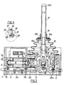
- the control device 1 shown in FIGS. 1 and 2 comprises a lower cover 2a, an upper cover 2k fixed on either side of a plate 3 defining a housing intended to receive all of the control means fixed to this plate.
- Two electric torque motors 4 and 5 are fixed to the support plate 3 so that their shafts 6 are located perpendicularly in the horizontal plane (see Fig. 2).
- Each shaft 6 is mounted at each end in two ball bearings 7 fixed to the support plate by fixing rings 7a and screws 7h and is provided at the end directed towards the point of intersection of the axes of the two shafts, of a conical hoop coupling 8.
- This coupling is intended to allow a backlash-free connection of each shaft end with a res fork pective 9, 10.
- the forks 9 and 10 respectively consist of a cylindrical part 11 intended to come into engagement with the conical hoop coupling and of a curvilinear part 12, in the shape of an arc, offset with respect to the 'associated motor shaft, the amplitude of the offset being different for each fork which is provided with a central slot 13 (Fig.1) adapted to allow the passage of an operating handle 14.
- the offset arrangement and the curvature ( radii of curvature starting from the same center) of the parts 12 are such that they can each describe a rotational movement on each side of the vertical position in which the handle 14 is represented.
- the handle 14 is provided at its lower end with a ball joint 15 pivotally mounted in a housing 16 formed in the support plate 3 so that the center of the ball joint is located at the point of intersection of the axes of the two torque motors.
- the support plate 3 has, in the upper part of the housing, a flared shape at 16a intended to limit the angular movement of the handle.
- the central part of the handle 14 consists of a flare 14A on which a bellows 18 is pinched by a washer 19a and a flange 19b screwed onto the handle. The lower part of the bellows 18 is fixed to the upper cover 2Q.
- the ends of the curved portions 12 are each connected by a connecting device 20 to the shaft 21 of a rotary potentiometer 22.
- the housing of the potentiometer 22 is fixed to the support plate 2 by means of a fixing ring 23 fixed to its lower part by a screw 23a passing through the support plate 3.
- the connecting device 20 is shown in detail in Fig.3.
- This device includes a clamp 24 in which is housed the shaft 21 of the corresponding potentiometer 22, this shaft being tightened therein by means of a screw 25.
- a pin 26 is housed between a projecting part 27 of the clamp and an elastic plate 28 making facing the projecting part 27 and fixed on one side of the clamp by the screw 25. This pin 26 is at its other end fitted into a hole in the end of the corresponding fork 9 or 10.
- each potentiometer 22 is offset upwards relative to the axis of the shaft 6 carrying the fork 9 or 10 so that a rotation of 20 ° of the shaft on one side or the other of the point of rest causes a rotation of the potentiometer axis of approximately 30 * in the same direction of rotation and allows a sufficiently precise measurement of the rotation of the fork by variation of tension.
- the handle 14 is provided at its upper end with a push button 14b which finds its application in a control system and whose function will be described with reference to Figure 4.
- a spring 29 fork return in the absence of current in the device to a position corresponding to a vertical position of the handle 14 is fixed by one of its ends to a first sleeve 11A secured to the cylindrical part 11 of the fork 9 or 10 and by its other end to a second sleeve 11b surrounding a section of the cylindrical part 11 and secured by means of an annular spacer 7c to the fixing ring 7a of the ball bearing 7 located on the side of the fork 9 or 10
- the potentiometers and the inputs of the torque motors are electrically connected to an electrical circuit 30 whose configuration and functions will also be described in detail with reference to Figure 4.
- the forks 9 and 10 rotate simultaneously or separately around the axes of the torque motors, which causes both the shaft of the torque motor and the potentiometer to rotate associated.
- Each motor is connected to the midpoint of the corresponding potentiometer, the end terminals of which are connected to a voltage source, not shown, by means of an electrical circuit, not shown, so that these paired motors receive a current which creates a resisting torque opposite and directly proportional to their angular displacement relative to a determined position corresponding to the vertical position of the handle.
- This relationship of proportionality allows the operator to realize the importance of the pivoting movement of the handle relative to its vertical reference position.
- the resisting torque also allows the handle to be returned to a vertical position, the torsion springs 29 cause the handle to return automatically to its vertical position in the absence of current in the device.
- Such a control device can also be slaved to an electric remote control device by applying to the torque motors of this control device, via the electrical circuit 30, an electric current signal corresponding to a desired movement of the handle.
- an electric current signal corresponding to a desired movement of the handle.
- FIG 4 is a block diagram of a control system comprising two control devices 1 and 1 'as described above and a first 1 of which is intended to be actuated manually by an operator, the second 1' being electrically connected to the first device so as to be subject to actuation performed on this first.
- first and second control devices will be called hereinafter respectively chief or master control devices and pointer or slave control device.
- master control devices For the purpose of simplification of manufacture, reduction of the cost and possibility of versatility, these control devices are identical, so that only the structure of the control device 1 will be described below, the components of the control device 1 ' corresponding to those of device 1 having the same references distinguished by the sign "'".
- the control device 1 comprises a relay 31 connected to earth on the one hand, and to one of the terminals of the push button 14h on the other hand.
- the other terminal of the push button 14b is connected to a first output terminal A of the control device, intended to be connected to a 27 volt voltage supply source, not shown.
- a diode 32 is connected by its cathode to terminal A and by its anode to an output terminal 8.
- a first closed contact 33 is connected between terminals A and B.
- Each of the motors 34 and 35 is connected respectively to a potentiometer 36 and 37 by the mechanical connection described with reference to FIGS. 1 to 3 and shown diagrammatically in FIG. 4.
- the outputs of potentiometers 36 and 37 are respectively connected to terminals of two switches 38 and 39, the middle terminals of which are respectively connected to device outputs C and D control, the third terminal being connected to ground.
- the outputs of potentiometers 36 and 37 are also connected to output terminals E and F of the control device on the one hand, and to the negative inputs of two subtractor circuits 40 and 41 on the other hand.
- the positive inputs of circuits 40 and 41 are respectively connected to the middle terminals of two switches 42 and 43, the other terminals of which are respectively connected to an input terminal G of the device and to ground, and to an input terminal H of the device and ground.
- Terminals C and 0 constitute the servo output terminals
- terminals E and F constitute the control output terminals
- terminals G and H constitute the servo input terminals of the control device.
- the outputs of the two subtractors 40 and 41 are respectively connected to filtering and amplification circuits 44 and 45 on which two open contacts 46 and 47 are respectively connected in parallel.
- the outputs of the filtering circuits 44 and 45 are respectively connected to inputs of two amplifier circuits 48 and 49, the outputs of which are connected respectively to the input terminals of the torque motors 34 and 35.
- Contacts 33, 46 and 47 and switches 38, 39, 42 and 43 are all controlled by the relay 31 and are, when the relay is not energized in the positions shown in Figure 4.
- the two control devices 1 and 1 ' are interconnected by the following connections B-B', C-G ', D -H ', C'-G and D'-H.
- the input terminal A is supplied with direct voltage of 27 volts unlike the terminal A 'due to the fact that in the example shown the control device 1 is the master device, while the control device 1 'is the pointer device.
- the O'-H and C'-G connections only exist for the event that the control device 1 'becomes the main device by connecting the + 27 volt voltage source being connected to the input terminal A' or during the transition to the firing phase as will be explained in relation to the operation of the system.
- the control output terminals EF and E '. F ' are intended respectively to be connected to the members (not shown) to be controlled by the control devices 1 and 1'.
- the electrical circuit 30 mentioned with reference to FIG. 1 comprises the components 31 to 33 and 38 to 49.
- the chief or pilot activates the button 14b in order to control the direction organs (for an airplane the site and the deposit) via the handle 14 and the control device 1.
- the relay 31 is energized by the supply voltage of 27 volts and the contacts 33, 46, 47 and the switches 38, 39, 42 and 43 switch.
- the positive inputs of the subtractor circuits 40 and 41 are grounded by switches 42 and 43 and the filters 44 and 45 are short-circuited by the contacts 46 and 47.
- switches 38 and 39 allow sending to the control device 1 ' of the pointer or shooter, via the servo output terminals G 'and H' and the servo input terminals H 'and G', of the site and field servo signals from the outputs of potentiometers 36 and 37.
- the contacts and switches of the control device of the shooter 1' thus remain in the position shown in Figure 4.
- the maneuver. of the handle 14 along the axes of the motors separately or simultaneously, causes the rotation of the torque motors 34 and 35 and, by means of the forks 9 and 10 and of the connection device 20. the rotation of the rotary potentiometers of site 36 and of deposit 37. Since the positive inputs of the subtractor circuits 40 and 41 are grounded and the filters 44 and 45 are short-circuited, a negative signal is obtained at their output, the amplitude of which is that of the output control signal from the potentiometers 36 and 37 respectively. . Thus, the motors 34 and 35 respectively receive, through the intermediaries of the amplifiers 45 and 46, a current creating an opposing resistive torque and directly proportional to the inclinations of the handle along the respective axes 6.
- the control signals applied to the inputs G 'and H' of the control device 1 ' are transmitted, via switches 42' and 43 'to the positive inputs of the subtractor circuits 40' and 41 '.
- the circuits 40 ′ and 41 ′ respectively perform the subtraction of these servo signals and of the output signals from the site potentiometers 37 ′ and of the field 36 ′ respectively.
- the output signals from these subtractor circuits 40 'and 41' are respectively applied to the torque motors 34 'and 35' via circuits 44 'and 45' and amplifiers 48 'and 49' respectively.
- the application of this signal causes the rotation of the motors, forks, potentiometers and the pivoting of the handle according to the rotation of the forks.
- the chef can therefore maneuver his control device by pushing the 14h pick-up button and send control signals to the steering members and servo signals to the control device 1 ' of the shooter via his control stick.
- the chef feels on his own sleeve a force proportional to the angle of pivoting of the handle along the axes of the motors and he causes a displacement of the handle 14 ′ of the pointer control device identical to that of his own handle 14.
- the push button 14'R for taking over the pointer control device has no effect on the control device of the chief.
- the pointer feels, as soon as it makes a small movement of its stick relative to the position imposed by the device. command 1, the full resistant resistance of the torque motors indicating that it is guided by the chef. If the chef releases the push button 14k, the control input signals H 'and G' become zero and the handle 14 'of the control device 1' returns to its vertical position thanks to the return springs 29 '(not shown) .
- the shooter control device 1 ′ is always in the optimal firing position when the leader engages in combat or pursuit by acting on his control stick 14 and by actuating the push button 14b.
- the site and deposit control channels are reversed in the control devices 1 and 1 ′ in order to simplify the representation of the connections between these two devices. but it goes without saying that these devices can be manufactured identically.
- each of the devices indifferently as master or shooter control devices by connecting the 27-volt voltage source to the input terminal A or A ', the other connections remaining unchanged.
- the control outputs E and F of the leader's device and the control output terminals E 'and F' of the shooter's control device are connected to the orientation means of the control system.
- the chef then releases the push button 14b. allowing the pointer thanks to the circuit 33 and the diode 32 ', to take charge of the system by actuation of its push button 14h.
- the "slave" control device 1 'then becomes “master” and controls the control device 1 which nevertheless retains the priority of taking over the system from actuating the push button 14b. So when the firing phase is over, the chef can take over the system with his control stick 14 in the right position, which accelerates and secures the transfer of care.
- the assembly constituted by the forks 9, 10 and the couplings with a conical hoop has been given only by way of nonlimiting example.
- the forks 9, 10 constitute means for transforming the rotational movement of the shafts 6 of the torque motors 4, 5 into a pivoting movement of the control stick 14 and vice versa, and can be replaced by any equivalent suitable means.
Landscapes
- Engineering & Computer Science (AREA)
- Physics & Mathematics (AREA)
- General Physics & Mathematics (AREA)
- Automation & Control Theory (AREA)
- General Engineering & Computer Science (AREA)
- Mechanical Control Devices (AREA)
- Feedback Control In General (AREA)
- Control Of Position Or Direction (AREA)
- Electric Propulsion And Braking For Vehicles (AREA)
Applications Claiming Priority (2)
| Application Number | Priority Date | Filing Date | Title |
|---|---|---|---|
| FR8514391A FR2590044B1 (fr) | 1985-09-27 | 1985-09-27 | Dispositif de commande electrique motorise |
| FR8514391 | 1985-09-27 |
Publications (2)
| Publication Number | Publication Date |
|---|---|
| EP0223631A1 true EP0223631A1 (de) | 1987-05-27 |
| EP0223631B1 EP0223631B1 (de) | 1991-01-23 |
Family
ID=9323340
Family Applications (1)
| Application Number | Title | Priority Date | Filing Date |
|---|---|---|---|
| EP86402070A Expired - Lifetime EP0223631B1 (de) | 1985-09-27 | 1986-09-19 | Elektrische Steuervorrichtung mit Motor |
Country Status (5)
| Country | Link |
|---|---|
| US (1) | US4772836A (de) |
| EP (1) | EP0223631B1 (de) |
| JP (1) | JPS6274109A (de) |
| DE (1) | DE3677146D1 (de) |
| FR (1) | FR2590044B1 (de) |
Families Citing this family (9)
| Publication number | Priority date | Publication date | Assignee | Title |
|---|---|---|---|---|
| FR2647922B1 (fr) * | 1989-05-31 | 1993-12-31 | Sextant Avionique | Dispositif de commande electromecanique utilisable pour le pilotage d'un vehicule |
| ES2162141T3 (es) * | 1996-03-08 | 2001-12-16 | Zf Lemfoerder Metallwaren Ag | Dispositivo de conmutacion para un cambio de marchas de vehiculos de motor. |
| DE19926784A1 (de) * | 1999-06-11 | 2000-12-14 | Wittenstein Gmbh & Co Kg | Vorrichtung zum Steuern einer Einrichtung |
| JP3710653B2 (ja) * | 1999-08-10 | 2005-10-26 | ホシデン株式会社 | 多方向入力装置 |
| JP3664665B2 (ja) * | 2001-06-01 | 2005-06-29 | 株式会社カワサキプレシジョンマシナリ | ジョイスティック装置 |
| CN102589351B (zh) * | 2012-03-07 | 2014-11-26 | 成都信息工程学院 | 一种基于人影高炮作业参数的数字化采集装置及其检测方法 |
| JP6641211B2 (ja) * | 2016-03-23 | 2020-02-05 | 大裕株式会社 | 重機の遠隔操作装置 |
| JP6778982B2 (ja) * | 2017-08-25 | 2020-11-04 | 東芝三菱電機産業システム株式会社 | 荷役機器の操作システム |
| WO2025223661A1 (en) | 2024-04-25 | 2025-10-30 | Merit Automotive Electronics Systems S.L.U. | Haptic switch assembly with a tilting switching member |
Citations (6)
| Publication number | Priority date | Publication date | Assignee | Title |
|---|---|---|---|---|
| US3497668A (en) * | 1966-08-25 | 1970-02-24 | Joseph Hirsch | Tactile control system |
| DE2015326A1 (de) * | 1969-03-31 | 1971-03-11 | Automatische Korrektureinrichtung fur Geschutzsysteme Annr Etat Francais, vertreten durch den Mimstre des Armees (Armement), Paris | |
| DE1967002A1 (de) * | 1969-09-20 | 1976-01-15 | Licentia Gmbh | Schaltungsanordnung zum steuern zweier elektromotore mittels einer kreuzknueppelmechanik |
| FR2484626A1 (fr) * | 1980-06-11 | 1981-12-18 | Applic Mach Motrices | Dispositif de commande automatique de poursuite d'une cible, notamment pour char anti-aerien |
| EP0023864B1 (de) * | 1979-08-02 | 1983-07-06 | Association Des Ouvriers En Instruments De Precision | Handbetätigte Führungsvorrichtung, insbesondere Handgriff zum Führen der Bewegungen eines angetriebenen Werkzeuges |
| DE3238048A1 (de) * | 1982-10-14 | 1984-04-19 | W. Gessmann GmbH, 7105 Leingarten | Verbundantrieb fuer schalt- oder stellglieder |
Family Cites Families (9)
| Publication number | Priority date | Publication date | Assignee | Title |
|---|---|---|---|---|
| US3644816A (en) * | 1970-12-21 | 1972-02-22 | Gen Electric | Manual and automatic master-slave control system |
| GB1490083A (en) * | 1974-03-14 | 1977-10-26 | Marconi Co Ltd | Control arrangements |
| FR2275816A1 (fr) * | 1974-06-19 | 1976-01-16 | Commissariat Energie Atomique | Dispositif de commande d'un organe mecanique avec retour d'effort |
| FR2484628A1 (fr) * | 1980-02-20 | 1981-12-18 | Eternit Financiere | Appareil de controle de pas d'onde |
| FR2512570A1 (fr) * | 1981-09-09 | 1983-03-11 | Commissariat Energie Atomique | Systeme d'asservissement de position a retour d'effort avec retard de transmission et son application a un telemanipulateur |
| SE431432B (sv) * | 1982-06-01 | 1984-02-06 | Saab Scania Ab | Styrdon |
| US4471280A (en) * | 1983-05-06 | 1984-09-11 | The Bendix Corporation | Anti-log power amplifier for reversible D.C. motor in automotive steering controls |
| DE3431583A1 (de) * | 1984-08-28 | 1986-03-13 | Messerschmitt-Bölkow-Blohm GmbH, 8012 Ottobrunn | Vorrichtung zur automatischen beseitigung von steuerkraftfehlern bei luftfahrzeugen, insbesondere hubschraubern |
| US4608526A (en) * | 1985-04-19 | 1986-08-26 | The United States Of America As Represented By The United States Department Of Energy | Electromechanical actuator for the tongs of a servomanipulator |
-
1985
- 1985-09-27 FR FR8514391A patent/FR2590044B1/fr not_active Expired
-
1986
- 1986-09-19 DE DE8686402070T patent/DE3677146D1/de not_active Expired - Lifetime
- 1986-09-19 EP EP86402070A patent/EP0223631B1/de not_active Expired - Lifetime
- 1986-09-26 US US06/911,940 patent/US4772836A/en not_active Expired - Fee Related
- 1986-09-27 JP JP61229483A patent/JPS6274109A/ja active Granted
Patent Citations (6)
| Publication number | Priority date | Publication date | Assignee | Title |
|---|---|---|---|---|
| US3497668A (en) * | 1966-08-25 | 1970-02-24 | Joseph Hirsch | Tactile control system |
| DE2015326A1 (de) * | 1969-03-31 | 1971-03-11 | Automatische Korrektureinrichtung fur Geschutzsysteme Annr Etat Francais, vertreten durch den Mimstre des Armees (Armement), Paris | |
| DE1967002A1 (de) * | 1969-09-20 | 1976-01-15 | Licentia Gmbh | Schaltungsanordnung zum steuern zweier elektromotore mittels einer kreuzknueppelmechanik |
| EP0023864B1 (de) * | 1979-08-02 | 1983-07-06 | Association Des Ouvriers En Instruments De Precision | Handbetätigte Führungsvorrichtung, insbesondere Handgriff zum Führen der Bewegungen eines angetriebenen Werkzeuges |
| FR2484626A1 (fr) * | 1980-06-11 | 1981-12-18 | Applic Mach Motrices | Dispositif de commande automatique de poursuite d'une cible, notamment pour char anti-aerien |
| DE3238048A1 (de) * | 1982-10-14 | 1984-04-19 | W. Gessmann GmbH, 7105 Leingarten | Verbundantrieb fuer schalt- oder stellglieder |
Also Published As
| Publication number | Publication date |
|---|---|
| FR2590044B1 (fr) | 1988-01-29 |
| FR2590044A1 (fr) | 1987-05-15 |
| US4772836A (en) | 1988-09-20 |
| JPH0511322B2 (de) | 1993-02-15 |
| JPS6274109A (ja) | 1987-04-04 |
| EP0223631B1 (de) | 1991-01-23 |
| DE3677146D1 (de) | 1991-02-28 |
Similar Documents
| Publication | Publication Date | Title |
|---|---|---|
| EP0383663B1 (de) | Steuervorrichtung mit einem schwenkbaren Knüppel und damit ausgerüstetes Flugsteuerungssystem eines Flugzeuges | |
| EP0384806B1 (de) | Steuervorrichtung mit Schwenkhebel, insbesondere für Flugzeug, und System mit zwei solcher Vorrichtungen | |
| CH661989A5 (fr) | Manipulateur analogique. | |
| EP0718731A1 (de) | Vorrichtung zum Betreiben eines gesteuerten Elementes für ein Flugzeug, insbesondere Hubschrauber, mit elektrischen Flugsteuerungen | |
| FR3001706A1 (fr) | Mini-manche de commande electromecanique a retour d'effort | |
| EP0223631B1 (de) | Elektrische Steuervorrichtung mit Motor | |
| EP0844171A1 (de) | Kopplungssystem für eine Steuerknüppeleinheit | |
| US7694913B2 (en) | Apparatus and method for reduced backlash steering tiller | |
| FR2583017A1 (fr) | Dispositif de commande pourvu de deux manches couples | |
| WO2008141676A1 (fr) | Mécanisme de direction, en particulier pour véhicules courts | |
| FR2899871A1 (fr) | Atterisseur comportant plusieurs actionneurs electromecaniques d'orientation | |
| EP0316249A1 (de) | Flugzeugkarussell mit Steigflugeffekt | |
| WO2021197814A1 (fr) | Interface homme-machine | |
| EP1160158B1 (de) | Elektrisches Seitenrudersteuerungssystem für Luftfahrzeuge | |
| FR2656574A1 (fr) | Phare pour vehicule a faisceau orientable. | |
| WO2015150439A2 (fr) | Dispositif de commande passif magnétique | |
| FR2931132A1 (fr) | Systeme de commande assiste d'un giravon | |
| EP3045396A1 (de) | Ausrichtungseinheit eines instrumentes | |
| EP0313470B1 (de) | Kupplungsstange mit Kontakt für die Steuerung des Fluges eines Luftfahrzeuges | |
| FR2476013A1 (fr) | Dispositif de commande pour avions a caracteristiques differentes en vol lent et en vol rapide | |
| FR2872128A1 (fr) | Dispositif de restitution artificielle d'effort antagoniste pour un dispositif de commande a distance de gouvernes d'un aeronef | |
| EP4472888B1 (de) | Antriebsvorrichtung für eine senkrecht startende und landende drehflügel-aerodyne und eine mit einer solchen antriebsvorrichtung ausgestattete aerodyne | |
| EP0010480B1 (de) | Servo-unterstützte handbediente Anordnung zur Zielerfassung für ein Richtgerät | |
| EP0125991A1 (de) | Steuerknüppel für Konsole | |
| WO2020048757A1 (fr) | Dispositif de commande de vol d'un aeronef |
Legal Events
| Date | Code | Title | Description |
|---|---|---|---|
| PUAI | Public reference made under article 153(3) epc to a published international application that has entered the european phase |
Free format text: ORIGINAL CODE: 0009012 |
|
| AK | Designated contracting states |
Kind code of ref document: A1 Designated state(s): DE GB IT |
|
| 17P | Request for examination filed |
Effective date: 19870807 |
|
| 17Q | First examination report despatched |
Effective date: 19881212 |
|
| GRAA | (expected) grant |
Free format text: ORIGINAL CODE: 0009210 |
|
| AK | Designated contracting states |
Kind code of ref document: B1 Designated state(s): DE GB IT |
|
| ITF | It: translation for a ep patent filed | ||
| GBT | Gb: translation of ep patent filed (gb section 77(6)(a)/1977) | ||
| REF | Corresponds to: |
Ref document number: 3677146 Country of ref document: DE Date of ref document: 19910228 |
|
| PLBE | No opposition filed within time limit |
Free format text: ORIGINAL CODE: 0009261 |
|
| STAA | Information on the status of an ep patent application or granted ep patent |
Free format text: STATUS: NO OPPOSITION FILED WITHIN TIME LIMIT |
|
| 26N | No opposition filed | ||
| REG | Reference to a national code |
Ref country code: GB Ref legal event code: IF02 |
|
| PGFP | Annual fee paid to national office [announced via postgrant information from national office to epo] |
Ref country code: GB Payment date: 20040915 Year of fee payment: 19 |
|
| PGFP | Annual fee paid to national office [announced via postgrant information from national office to epo] |
Ref country code: DE Payment date: 20040916 Year of fee payment: 19 |
|
| PG25 | Lapsed in a contracting state [announced via postgrant information from national office to epo] |
Ref country code: IT Free format text: LAPSE BECAUSE OF NON-PAYMENT OF DUE FEES;WARNING: LAPSES OF ITALIAN PATENTS WITH EFFECTIVE DATE BEFORE 2007 MAY HAVE OCCURRED AT ANY TIME BEFORE 2007. THE CORRECT EFFECTIVE DATE MAY BE DIFFERENT FROM THE ONE RECORDED. Effective date: 20050919 Ref country code: GB Free format text: LAPSE BECAUSE OF NON-PAYMENT OF DUE FEES Effective date: 20050919 |
|
| PG25 | Lapsed in a contracting state [announced via postgrant information from national office to epo] |
Ref country code: DE Free format text: LAPSE BECAUSE OF NON-PAYMENT OF DUE FEES Effective date: 20060401 |
|
| GBPC | Gb: european patent ceased through non-payment of renewal fee |
Effective date: 20050919 |