EP0223675A1 - Brenner zum elektrischen Schweissen mit einer Vorrichtung zur Zündung des Lichtbogens - Google Patents
Brenner zum elektrischen Schweissen mit einer Vorrichtung zur Zündung des Lichtbogens Download PDFInfo
- Publication number
- EP0223675A1 EP0223675A1 EP86402357A EP86402357A EP0223675A1 EP 0223675 A1 EP0223675 A1 EP 0223675A1 EP 86402357 A EP86402357 A EP 86402357A EP 86402357 A EP86402357 A EP 86402357A EP 0223675 A1 EP0223675 A1 EP 0223675A1
- Authority
- EP
- European Patent Office
- Prior art keywords
- torch
- spark gap
- electrode
- welding
- electronic igniter
- Prior art date
- Legal status (The legal status is an assumption and is not a legal conclusion. Google has not performed a legal analysis and makes no representation as to the accuracy of the status listed.)
- Granted
Links
Images



Classifications
-
- B—PERFORMING OPERATIONS; TRANSPORTING
- B23—MACHINE TOOLS; METAL-WORKING NOT OTHERWISE PROVIDED FOR
- B23K—SOLDERING OR UNSOLDERING; WELDING; CLADDING OR PLATING BY SOLDERING OR WELDING; CUTTING BY APPLYING HEAT LOCALLY, e.g. FLAME CUTTING; WORKING BY LASER BEAM
- B23K9/00—Arc welding or cutting
- B23K9/06—Arrangements or circuits for starting the arc, e.g. by generating ignition voltage, or for stabilising the arc
- B23K9/067—Starting the arc
- B23K9/0672—Starting the arc without direct contact between electrodes
- B23K9/0673—Ionisation of the arc gap by means of pulsed or high-frequency voltages
Definitions
- the invention relates to the initiation of an arc by welding or electrical cutting with an electrode, in particular a refractory electrode, of the type where one causes, between a refractory electrode, and either an auxiliary electrode adjacent to said refractory electrode, or a part. soldering or cutting an ionizing discharge of high voltage electrical pulses forming at least one spark from a pulse generator.
- the discharge of high voltage electrical pulses is ensured by means of a high frequency generator, which is necessarily arranged, due to its weight and size, at a distance from the welding torch and in general more or less integrated. to the welding current generator.
- a high frequency generator which is necessarily arranged, due to its weight and size, at a distance from the welding torch and in general more or less integrated. to the welding current generator.
- Such a way of creating, at the refractory electrode, a high frequency electrical discharge has significant drawbacks with regard to the very expensive price of the high frequency generator and the environmental nuisance of these discharges causing radio interference. electrical, in particular for telecommunications and automation electronics on installations.
- the efficiency of the high frequency discharge is very dependent on the distance between the generator and the torch, so that one is obliged to oversize the high frequency generator to take into account the sometimes relatively large distances between welding station and welding generator, which further increases the drawbacks mentioned above.
- the distance between said spark gap and said refractory electrode is less than 0.5 meters, the spark gap being preferably housed at, or in, the torch body.
- electronic igniter small spark generators, or spark train, incorporating at least one electrical capacitance with its charge and discharge means with voltage rise, which are commonly found in commerce and whose none of the three dimensions generally exceed 10 years and whose weight is relatively light on the order of 100 g to 200 g, while the power of a spark is on the order of 10 millijoules.
- An igniter of this type is sold by the French RV Company under the trade name REF 177 "Electronic igniter 1 or 2 points". It is one of the merits of the present invention to have been able to discern that such a generator of small overall dimensions and weight could be easily added without difficulty near the body of the torch itself, or in the bundle of cables and conduits of which said torch is equipped and whose length does not generally exceed eight meters.
- this spark gap had to be placed fairly close to the ignition electrode and in any case at a distance of less than 0.5 m. Beyond this, the attenuation of the electric shock risks making the ignition of the main arc random.
- the invention also relates to an electric welding torch, of the type comprising a torch body with a refractory electrode, an annular conduit coaxial with said electrode for a shielding gas, said electrode and said conduit being connected to supply means by a supply bundle incorporating an electric cable for the welding current, a conduit for the shielding gas, if necessary supply and return conduits for a cooling fluid, and control conductors, and this torch for welding is characterized in that the electronic igniter is placed at the farthest at one end of said beam which is that which is distant from the torch body, with a spark gap in series.
- the electronic igniter is incorporated into said quick connector.
- the water inlet connection for a pipe 15 is of the same type, but does not incorporate any electric cable.
- the various conduits and conductors 9, 13 and 14, 15 are grouped in a bundle 20 with an insulating envelope and in the upstream end portion 22 is provided a rigid plastic envelope 23 formed by two double shells 24-25 having a prominence 26 so as to incorporate an electronic igniter 27, of the type mentioned previously.
- This electronic igniter 27 has two high voltage output terminals 30 and 31, the terminal 30 being electrically connected via a conductor 32 to the conductive parts of the quick connector, therefore to the welding current cable 14, while the high voltage terminal 31 is connected to a high voltage conductor 33 engaged in the bundle of conductors 20.
- the base 5 of the quick connector which may be the wall of the welding generator, further carries two connectors 40 and 41.
- the connector 40 used to connect one or more low-voltage control conductors 42, while the quick connector 41 serves to the connection of two electric wires 43 connected to the low voltage terminals of the electronic igniter 27.
- the conductor bundle 20 which has a certain flexibility (over a few meters, at most eight meters), extends to the welding torch shown in FIGS. 3 and 4 which will now be described.
- the water supply pipe is shown at 54.
- the high voltage conductor 33 continues inside the handle 50 and is connected by a split pin 60 to a metal rod 61, all electrically protected by a flange 62 and an insulating tube 63.
- the metal rod 61 is electrically connected by a conductive bracket 64 to a metal nozzle ring 65, which is fixed to the external surface a torch nozzle 66 incorporating the electrode holder 56 and a part 67 forming with the electrode holder 56 an annular conduit 68 for the shielding gas.
- the operation is as follows: at the start of a welding operation, the operator presses on a not shown trigger, which allows, thanks to the control conductors 42, not only to ensure the supply of fluids, (cooling water, gas protection) and welding current, but also the connection of the electronic igniter.
- the operator then approaches the welding torch to the piece to be welded 71 and by tilting it so that the edge 72 of nozzle 66 comes into contact with a piece to be welded 71, and it occurs between the ring 65 and the piece to weld 71 a correct distance (a) of the order of 2 to 8 millimeters which forms with the distance b of the zone to be ionized between the end of the electrode 56 and the part 71 the disruptive distance for electrical discharges.
- a discharge occurs between this conductive ring 65 and the part 71, a discharge which closes on the electrode 57 which is connected by the conductor 31 ( Figure 1) to the other high voltage terminal of the electronic igniter, causing an ionizing spark in the arc-forming space between the end of the electrode 57 and the part 71 .
- a torch body 101 with an electrode 102 electrically connected to a tubular conductor 103 for the welding current also carrying the protective gas flowing in the interstitial space 104 two conductors 105 and 106 coming from the electronic igniter (for example connected to the high voltage terminals 31 and 32 of the igniter 27 according to FIG. 1).
- the conductor 105 leads to a spark gap 107 formed by two metal points 108 and 109 one 108 at the end of the conductor 105, the other 109 connected by brazing to the tubular conductor 103 of the welding current.
- the conductor 106 is itself connected to a socket 110 engaged in a pin 111, the whole insulated by an insulation flange 112.
- the pin 111 is connected by a metal rod 113 to a nozzle ring 114 made of conductive material placed at the nozzle terminal level 115, therefore suitable for coming into direct contact with the part to be welded during ignition.
- two conductors 121, 122 are found in a torch 120, one of which 122 is connected to an HV terminal of the electronic igniter (as shown in FIG. 1), the other HV terminal of this igniter being immediately connected to the welding current conductor, as shown in Figure 1.
- the conductor 121 is connected to a low voltage supply terminal of this igniter, while the other low voltage terminal of the The igniter is connected via a blocking coil to the welding current conductor.
- the conductors 121 and 122 have end portions 123 and 124 of different lengths, opposite a conductive plate 125 embedded in an insulating tip 126 of a collar 127, all so that the end portion 123 of the conductor 121 is in contact with the plate 125, while the end portion 124 of the conductor 122 is at a distance from the spark gap of this same plate 125.
- the plate 125 is in electrical connection with a rod 128 leading to a nozzle collar conductive 129.
- the low voltage supply circuit of the igniter is closed and a spark or a train of sparks is carried by the welding current conductor, the ionization space between electrode 57 and part 71, flange 129, rod 128, spark gap 124-125 and conductor 122, the discharge H T ne can return to the input of the electronic igniter.
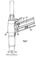
- a torch 150 with an electrode 152 electrically connected to a tubular conductor 153 for the shielding gas flowing in the interstitial space 154.
- a high voltage conductor well insulated but unshielded 155 is connected by a lug 156 to a metal part 157, the whole placed in a longitudinal housing 158 forming part of a torch handle 159, having an upstream lateral opening 160 forming an inlet crossing for the high cable voltage and a downstream opening 161, which is opposite the electrode end 162.
- a finger 163 at the spark gap distance from the shot 157 and which is electrically connected via a conductive sleeve 164 to the water return tube 165 which itself forms an electrical supply conductor for the welding current for the electrode 152.
Landscapes
- Engineering & Computer Science (AREA)
- Physics & Mathematics (AREA)
- Plasma & Fusion (AREA)
- Mechanical Engineering (AREA)
- Arc Welding In General (AREA)
- Arc Welding Control (AREA)
- Plasma Technology (AREA)
- Generation Of Surge Voltage And Current (AREA)
Applications Claiming Priority (2)
| Application Number | Priority Date | Filing Date | Title |
|---|---|---|---|
| FR8515863A FR2589307B1 (fr) | 1985-10-25 | 1985-10-25 | Procede d'amorcage d'un arc en soudage electrique et torche de soudage mettant en oeuvre ce procede |
| FR8515863 | 1985-10-25 |
Publications (2)
| Publication Number | Publication Date |
|---|---|
| EP0223675A1 true EP0223675A1 (de) | 1987-05-27 |
| EP0223675B1 EP0223675B1 (de) | 1990-09-05 |
Family
ID=9324195
Family Applications (1)
| Application Number | Title | Priority Date | Filing Date |
|---|---|---|---|
| EP86402357A Expired - Lifetime EP0223675B1 (de) | 1985-10-25 | 1986-10-22 | Brenner zum elektrischen Schweissen mit einer Vorrichtung zur Zündung des Lichtbogens |
Country Status (7)
| Country | Link |
|---|---|
| US (1) | US4855566A (de) |
| EP (1) | EP0223675B1 (de) |
| JP (1) | JPS63501550A (de) |
| DE (1) | DE3673956D1 (de) |
| ES (1) | ES2017467B3 (de) |
| FR (1) | FR2589307B1 (de) |
| WO (1) | WO1987002606A1 (de) |
Cited By (1)
| Publication number | Priority date | Publication date | Assignee | Title |
|---|---|---|---|---|
| FR2650522A1 (fr) * | 1989-08-03 | 1991-02-08 | Soudure Autogene Francaise | Installation de torche de soudage coupage electrique |
Families Citing this family (9)
| Publication number | Priority date | Publication date | Assignee | Title |
|---|---|---|---|---|
| US7542836B1 (en) * | 1993-11-23 | 2009-06-02 | Peter Norton | Vehicle occupant presence and position sensing system |
| US7321106B2 (en) * | 2004-09-10 | 2008-01-22 | Lincoln Global, Inc. | TIG welding torch |
| US7329833B2 (en) * | 2005-02-07 | 2008-02-12 | Illinois Tool Works Inc. | System for improved high-frequency arc starting of a welding process |
| US20060263016A1 (en) * | 2005-05-18 | 2006-11-23 | 3Sae Technologies, Inc. | Method and apparatus for fusion splicing optical fibers |
| US7342198B2 (en) * | 2005-08-05 | 2008-03-11 | 3Sae Technologies, Inc. | Method and apparatus for generating an electrical arc |
| US7555188B2 (en) * | 2005-08-05 | 2009-06-30 | 3Sae Technologies, Inc. | Method of cleaning and stripping an optical fiber using an electrical arc, and associated apparatus |
| US9687931B2 (en) | 2006-12-05 | 2017-06-27 | Lincoln Global, Inc. | System for measuring energy using digitally controlled welding power sources |
| DE102006043727A1 (de) * | 2006-09-13 | 2008-03-27 | Messer Cutting & Welding Gmbh | Schneidbrenner mit elektrischer Innenzündeinrichtung |
| US8217305B2 (en) | 2007-12-05 | 2012-07-10 | Illinois Tool Works Inc. | System and method for improved TIG arc starting |
Citations (5)
| Publication number | Priority date | Publication date | Assignee | Title |
|---|---|---|---|---|
| GB1146283A (en) * | 1965-03-15 | 1969-03-26 | Air Prod Ltd | Improvements in or relating to direct current electric arc initiation |
| FR2052152A5 (en) * | 1969-07-23 | 1971-04-09 | Commissariat Energie Atomique | Arc striking appts for arc welding |
| DE2709007A1 (de) * | 1977-03-02 | 1978-09-07 | Messer Griesheim Gmbh | Vorrichtung zur beruehrungslosen zuendung von lichtboegen |
| GB2061035A (en) * | 1977-09-26 | 1981-05-07 | Thermal Dynamics Corp | Plasma torch power supply circuit |
| GB2115993A (en) * | 1982-02-11 | 1983-09-14 | Welding Inst | Initiation of welding arcs |
Family Cites Families (3)
| Publication number | Priority date | Publication date | Assignee | Title |
|---|---|---|---|---|
| US2612582A (en) * | 1949-07-11 | 1952-09-30 | Arc Mfg Company Ltd | Combined arc welding electrode holder and high-frequency generator |
| US3008036A (en) * | 1959-11-13 | 1961-11-07 | Air Reduction | Initiating and stabilizing welding arcs |
| GB1571223A (en) * | 1976-04-20 | 1980-07-09 | Inst Zavaryavane | Device for producing pulses for the ignition and stabilization of electric arc prcesses |
-
1985
- 1985-10-25 FR FR8515863A patent/FR2589307B1/fr not_active Expired - Fee Related
-
1986
- 1986-10-22 ES ES86402357T patent/ES2017467B3/es not_active Expired - Lifetime
- 1986-10-22 US US07/054,272 patent/US4855566A/en not_active Expired - Fee Related
- 1986-10-22 WO PCT/FR1986/000363 patent/WO1987002606A1/fr not_active Ceased
- 1986-10-22 JP JP61505669A patent/JPS63501550A/ja active Pending
- 1986-10-22 EP EP86402357A patent/EP0223675B1/de not_active Expired - Lifetime
- 1986-10-22 DE DE8686402357T patent/DE3673956D1/de not_active Expired - Lifetime
Patent Citations (5)
| Publication number | Priority date | Publication date | Assignee | Title |
|---|---|---|---|---|
| GB1146283A (en) * | 1965-03-15 | 1969-03-26 | Air Prod Ltd | Improvements in or relating to direct current electric arc initiation |
| FR2052152A5 (en) * | 1969-07-23 | 1971-04-09 | Commissariat Energie Atomique | Arc striking appts for arc welding |
| DE2709007A1 (de) * | 1977-03-02 | 1978-09-07 | Messer Griesheim Gmbh | Vorrichtung zur beruehrungslosen zuendung von lichtboegen |
| GB2061035A (en) * | 1977-09-26 | 1981-05-07 | Thermal Dynamics Corp | Plasma torch power supply circuit |
| GB2115993A (en) * | 1982-02-11 | 1983-09-14 | Welding Inst | Initiation of welding arcs |
Cited By (1)
| Publication number | Priority date | Publication date | Assignee | Title |
|---|---|---|---|---|
| FR2650522A1 (fr) * | 1989-08-03 | 1991-02-08 | Soudure Autogene Francaise | Installation de torche de soudage coupage electrique |
Also Published As
| Publication number | Publication date |
|---|---|
| JPS63501550A (ja) | 1988-06-16 |
| EP0223675B1 (de) | 1990-09-05 |
| US4855566A (en) | 1989-08-08 |
| FR2589307B1 (fr) | 1993-07-30 |
| DE3673956D1 (de) | 1990-10-11 |
| FR2589307A1 (fr) | 1987-04-30 |
| ES2017467B3 (es) | 1991-02-16 |
| WO1987002606A1 (fr) | 1987-05-07 |
Similar Documents
| Publication | Publication Date | Title |
|---|---|---|
| EP0223675A1 (de) | Brenner zum elektrischen Schweissen mit einer Vorrichtung zur Zündung des Lichtbogens | |
| FR2636168A1 (fr) | Electrode d'amorcage en spirale pour lampes a decharge de haute intensite | |
| FR2831243A1 (fr) | Bougie de prechauffage pour un moteur diesel et procede de fabrication associe | |
| EP0427592B1 (de) | Plasmabrenner mit Kurzschlusslichtbogenzündung | |
| EP0109891B1 (de) | Hochfrequenzstarteinrichtung und Hilfselektrode eines elektrischen Schweiss- oder Schneidlichtbogens | |
| FR2953977A1 (fr) | Dispositif de raccordement electrique d'une barre appartenant a un jeu de barres a une traversee electrique appartenant a l'enveloppe isolante d'un appareil electrique de coupure | |
| CN1050554C (zh) | 电焊弧的点火方法 | |
| FR2502844A1 (fr) | Tube a decharge electrique et flash electronique le mettant en oeuvre | |
| CA2246651A1 (fr) | Dispositif de protection etanche pour une jonction de cables haute tension | |
| EP0427591B1 (de) | Plasmabrenner mit nicht gekühlter Plasmagasinjektion | |
| EP0427590B1 (de) | Plasmabrenner mit elektromagnetischer Spule zur Rotierung des Lichtbogens | |
| FR2552964A1 (fr) | Torche a plasma a energie hyperfrequence | |
| CA2069800C (fr) | Dispositif de protection contre les effets d'un claquage pour extremite de cable electrique | |
| FR2772979A1 (fr) | Dispositif de raccordement electrique d'un bloc differentiel sur un disjoncteur ou analogue et bloc differentiel equipe d'un tel dispositif | |
| EP0402552A1 (de) | Blitzableiter mit hoher Ionisierung und schwingendem Hochspannungsumformer | |
| FR2657216A1 (fr) | Inducteur pour un four a induction, comportant un tube parcouru par un liquide de refroidissement. | |
| FR2836278A1 (fr) | Traversee de courant sous enveloppe metallique etanche au gaz | |
| EP0802600B1 (de) | Gasisoliertes elektrisches Kabel | |
| EP0073168A2 (de) | Brenner zum Schneiden, Schweissen oder Erwärmen | |
| FR2792395A1 (fr) | Dispositif d'allumage pour bruleur et bruleur equipe d'un tel dispositif | |
| EP0072764A2 (de) | Zündrohr für einen Schweissbrenner | |
| EP0067758B1 (de) | Blitz-lampe mit radialen elektrischen Verbindungen und mit Gas-Zufuhr | |
| FR2650522A1 (fr) | Installation de torche de soudage coupage electrique | |
| FR2698300A1 (fr) | Appareil de soudage à l'arc en atmosphère inerte avec électrode de tungstène. | |
| FR2482480A1 (fr) | Pistolet de pulverisation electrostatique |
Legal Events
| Date | Code | Title | Description |
|---|---|---|---|
| PUAI | Public reference made under article 153(3) epc to a published international application that has entered the european phase |
Free format text: ORIGINAL CODE: 0009012 |
|
| 17P | Request for examination filed |
Effective date: 19861110 |
|
| AK | Designated contracting states |
Kind code of ref document: A1 Designated state(s): DE ES FR GB IT NL |
|
| 17Q | First examination report despatched |
Effective date: 19881208 |
|
| GRAA | (expected) grant |
Free format text: ORIGINAL CODE: 0009210 |
|
| AK | Designated contracting states |
Kind code of ref document: B1 Designated state(s): DE ES FR GB IT NL |
|
| ITF | It: translation for a ep patent filed | ||
| REF | Corresponds to: |
Ref document number: 3673956 Country of ref document: DE Date of ref document: 19901011 |
|
| GBT | Gb: translation of ep patent filed (gb section 77(6)(a)/1977) | ||
| PLBE | No opposition filed within time limit |
Free format text: ORIGINAL CODE: 0009261 |
|
| STAA | Information on the status of an ep patent application or granted ep patent |
Free format text: STATUS: NO OPPOSITION FILED WITHIN TIME LIMIT |
|
| 26N | No opposition filed | ||
| ITTA | It: last paid annual fee | ||
| PGFP | Annual fee paid to national office [announced via postgrant information from national office to epo] |
Ref country code: FR Payment date: 19970910 Year of fee payment: 12 |
|
| PGFP | Annual fee paid to national office [announced via postgrant information from national office to epo] |
Ref country code: GB Payment date: 19970918 Year of fee payment: 12 |
|
| PGFP | Annual fee paid to national office [announced via postgrant information from national office to epo] |
Ref country code: DE Payment date: 19970922 Year of fee payment: 12 |
|
| PGFP | Annual fee paid to national office [announced via postgrant information from national office to epo] |
Ref country code: NL Payment date: 19970923 Year of fee payment: 12 |
|
| PGFP | Annual fee paid to national office [announced via postgrant information from national office to epo] |
Ref country code: ES Payment date: 19971008 Year of fee payment: 12 |
|
| PG25 | Lapsed in a contracting state [announced via postgrant information from national office to epo] |
Ref country code: GB Free format text: LAPSE BECAUSE OF NON-PAYMENT OF DUE FEES Effective date: 19981022 |
|
| PG25 | Lapsed in a contracting state [announced via postgrant information from national office to epo] |
Ref country code: ES Free format text: THE PATENT HAS BEEN ANNULLED BY A DECISION OF A NATIONAL AUTHORITY Effective date: 19981023 |
|
| PG25 | Lapsed in a contracting state [announced via postgrant information from national office to epo] |
Ref country code: NL Free format text: LAPSE BECAUSE OF NON-PAYMENT OF DUE FEES Effective date: 19990501 |
|
| GBPC | Gb: european patent ceased through non-payment of renewal fee |
Effective date: 19981022 |
|
| PG25 | Lapsed in a contracting state [announced via postgrant information from national office to epo] |
Ref country code: FR Free format text: LAPSE BECAUSE OF NON-PAYMENT OF DUE FEES Effective date: 19990630 |
|
| NLV4 | Nl: lapsed or anulled due to non-payment of the annual fee |
Effective date: 19990501 |
|
| REG | Reference to a national code |
Ref country code: FR Ref legal event code: ST |
|
| PG25 | Lapsed in a contracting state [announced via postgrant information from national office to epo] |
Ref country code: DE Free format text: LAPSE BECAUSE OF NON-PAYMENT OF DUE FEES Effective date: 19990803 |
|
| REG | Reference to a national code |
Ref country code: ES Ref legal event code: FD2A Effective date: 20001204 |
|
| PG25 | Lapsed in a contracting state [announced via postgrant information from national office to epo] |
Ref country code: IT Free format text: LAPSE BECAUSE OF NON-PAYMENT OF DUE FEES;WARNING: LAPSES OF ITALIAN PATENTS WITH EFFECTIVE DATE BEFORE 2007 MAY HAVE OCCURRED AT ANY TIME BEFORE 2007. THE CORRECT EFFECTIVE DATE MAY BE DIFFERENT FROM THE ONE RECORDED. Effective date: 20051022 |