EP0223676A1 - Rotierende Laufwerkanlage für mindestens eine magnetische Platte und elektrischer Motor in dieser Anlage einbegriffen - Google Patents
Rotierende Laufwerkanlage für mindestens eine magnetische Platte und elektrischer Motor in dieser Anlage einbegriffen Download PDFInfo
- Publication number
- EP0223676A1 EP0223676A1 EP86402367A EP86402367A EP0223676A1 EP 0223676 A1 EP0223676 A1 EP 0223676A1 EP 86402367 A EP86402367 A EP 86402367A EP 86402367 A EP86402367 A EP 86402367A EP 0223676 A1 EP0223676 A1 EP 0223676A1
- Authority
- EP
- European Patent Office
- Prior art keywords
- inductor
- disc
- hub
- magnetic
- motor
- Prior art date
- Legal status (The legal status is an assumption and is not a legal conclusion. Google has not performed a legal analysis and makes no representation as to the accuracy of the status listed.)
- Withdrawn
Links
Images


Classifications
-
- H—ELECTRICITY
- H02—GENERATION; CONVERSION OR DISTRIBUTION OF ELECTRIC POWER
- H02K—DYNAMO-ELECTRIC MACHINES
- H02K7/00—Arrangements for handling mechanical energy structurally associated with dynamo-electric machines, e.g. structural association with mechanical driving motors or auxiliary dynamo-electric machines
- H02K7/14—Structural association with mechanical loads, e.g. with hand-held machine tools or fans
-
- G—PHYSICS
- G11—INFORMATION STORAGE
- G11B—INFORMATION STORAGE BASED ON RELATIVE MOVEMENT BETWEEN RECORD CARRIER AND TRANSDUCER
- G11B19/00—Driving, starting, stopping record carriers not specifically of filamentary or web form, or of supports therefor; Control thereof; Control of operating function ; Driving both disc and head
- G11B19/20—Driving; Starting; Stopping; Control thereof
- G11B19/2009—Turntables, hubs and motors for disk drives; Mounting of motors in the drive
-
- H—ELECTRICITY
- H02—GENERATION; CONVERSION OR DISTRIBUTION OF ELECTRIC POWER
- H02K—DYNAMO-ELECTRIC MACHINES
- H02K29/00—Motors or generators having non-mechanical commutating devices, e.g. discharge tubes or semiconductor devices
- H02K29/06—Motors or generators having non-mechanical commutating devices, e.g. discharge tubes or semiconductor devices with position sensing devices
- H02K29/08—Motors or generators having non-mechanical commutating devices, e.g. discharge tubes or semiconductor devices with position sensing devices using magnetic effect devices, e.g. Hall-plates, magneto-resistors
-
- H—ELECTRICITY
- H02—GENERATION; CONVERSION OR DISTRIBUTION OF ELECTRIC POWER
- H02K—DYNAMO-ELECTRIC MACHINES
- H02K5/00—Casings; Enclosures; Supports
- H02K5/04—Casings or enclosures characterised by the shape, form or construction thereof
- H02K5/10—Casings or enclosures characterised by the shape, form or construction thereof with arrangements for protection from ingress, e.g. water or fingers
-
- H—ELECTRICITY
- H02—GENERATION; CONVERSION OR DISTRIBUTION OF ELECTRIC POWER
- H02K—DYNAMO-ELECTRIC MACHINES
- H02K7/00—Arrangements for handling mechanical energy structurally associated with dynamo-electric machines, e.g. structural association with mechanical driving motors or auxiliary dynamo-electric machines
- H02K7/10—Structural association with clutches, brakes, gears, pulleys or mechanical starters
- H02K7/108—Structural association with clutches, brakes, gears, pulleys or mechanical starters with friction clutches
- H02K7/1085—Magnetically influenced friction clutches
-
- H—ELECTRICITY
- H02—GENERATION; CONVERSION OR DISTRIBUTION OF ELECTRIC POWER
- H02K—DYNAMO-ELECTRIC MACHINES
- H02K11/00—Structural association of dynamo-electric machines with electric components or with devices for shielding, monitoring or protection
Definitions
- the present invention relates to a system for driving in rotation at least one magnetic disc and the electric motor included in this system. It is more particularly applicable to the drive of magnetic disks belonging to the disk memories of information processing systems.
- magnetic disk memories include one or more coaxial disks which carry information generally contained on their two faces.
- the disc (s) comprise (s) a central hub which is coupled to the drive shaft of an electric motor by means of coupling means.
- the assembly formed by the electric motor and the coupling means constitutes a system for driving in rotation the magnetic disk (s). It allows the latter (s) to be driven at constant speed, usually 2400 or 3600 rpm.
- a motor of this type is for example used in the D-520 type disk memory sold by the applicant company.
- the magnetic permeability of the latter is high.
- the magnetic material constituting the latter is laminated or sintered.
- Such an electric motor is of the direct current type without collector. It is fitted with sensors, for example Hall or optical sensors. Because the windings are fixed, it is necessary to ensure a sequential switching of the current supplied by the direct current electric source to the various windings of the armature, in order to continuously produce the rotating field producing the rotation. It is therefore necessary to know at all times the position relative of the inductor with respect to the windings and this is obtained by now well known electronic methods using sensors of the type of those mentioned above. These provide electrical pulses making it possible to detect at any time the angular position of the inductor and consequently the position of each of the magnets thereof.
- the means for coupling the disc (s) to the shaft of the electric motor such as that described above are constituted by a permanent magnet in the form of a ring secured to the motor drive shaft and disposed between the upper part of the motor (next to the inductor) and the lower part of the disc hub arranged opposite the upper part of the motor .
- a permanent magnet in the form of a ring secured to the motor drive shaft and disposed between the upper part of the motor (next to the inductor) and the lower part of the disc hub arranged opposite the upper part of the motor .
- the motor drive shaft and the disc hub also include centering means making it possible to make the axis of rotation of the motor coincide with that of the disc hub.
- a drive system disc such as that described above remains too bulky, while the number of parts constituting it and therefore its cost are too high.
- the present invention overcomes these drawbacks by providing a disk drive system (s) comprising an ultra-thin motor, where the motor inductor, in addition to its traditional function of producing the motor torque, also ensures that of coupling of the motor drive shaft to the disc hub. This eliminates the magnet in the form of a ring arranged between the motor and the hub of the disc which traditionally assumed this coupling function.
- the MA motor comprises a fixed armature INDA above which is placed the mobile inductor INDUCA mounted on the shaft ARBA drive, and a CARCA carcass surrounding the armature and the inductor.
- This carcass is made of a material making it possible to prevent the inductor flux lines from passing outside the motor, mainly towards the disc, of which they would then disturb the information.
- the armature INDA, the inductor INDUCA, the drive shaft ARBA and the hub MOY of the disc DISC are coaxial and their common axis is the axis of rotation AX r around which rotates the disc DISC and the shaft of ARBA training.
- the INDA armature with high magnetic permeability comprises a plurality of electrical coils BOBA j in even number.
- the INDUCA inductor comprises a disk DA for example made of soft iron on which is arranged a cylindrical crown comprising eight magnetized sectors SM 1 to SM 8 , alternately of opposite magnetic polarity.
- the sectors SM 1 , SM 3 , SM 5 , SM 7 thus have a first magnetic polarity such that the upper part of the sector visible from above in FIG. 2 is considered for example as a north magnetic pole while its lower part is considered as a south magnetic pole (see also Figure 1 where the magnetic sector SM 7 is shown to the left of the axis of rotation AX r of the SMA drive system).
- the magnetic sectors SM 2 , SM 4 , SM 6 , SM 8 have a second magnetic polarity opposite to the first so that their upper part can be considered as a south magnetic pole and their lower part as a north magnetic pole (see the magnetic sector SM 4 shown to the right of the axis of rotation AX r of the drive system SEA in FIG. 1).
- the motor MA also includes three sensors CA i making it possible to determine the position at all times angle of the inductor of which only one is shown in Figure 1.
- the operation of the MA drive motor is that of a DC motor without a collector and has been briefly recalled above.
- the ACA coupling means consist of a ring-shaped magnet placed inside a cylindrical CYLA cup made of non-magnetic material.
- the CYLA cup is mounted integral with the ARBA shaft and the magnet ACA has an axis of symmetry which merges with the axis of rotation AX r of the disc DISC.
- the magnet ACA exerts a force of attraction (force of coupling) on the hub MOY and is in contact with its lower part PINF which is generally planar and has the shape of a circular crown, while being carried out in a material non-retentive magnetic.
- Figure 1 shows that it is difficult to further reduce the size of the SEA drive system and therefore the size of the disk memory containing it. Indeed, there is a limit beyond which it is no longer possible to bring the ACA magnet closer to the MA motor. Indeed, beyond this limit, there would be interference between the magnetic fields of the magnet ACA and the magnetic field of the different magnets of the inductor.
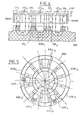
- the inductor simultaneously exercises two functions, namely on the one hand, the production of the motor torque and on the other hand the coupling of the ARBI shaft of the motor with the hub of the DISC disc via the air gap GI and the ANAMI cylindrical ring as will be better understood in the light of the description below.
- the inductor INDUCI comprises, like the inductor of the motor MA shown in FIG. 2, eight magnetized sectors SM l to SM 8 forming four pairs of poles P 1 , P 2 , P 3 , P 4 and is mounted on the shaft ARBI motor rotation drive. It has the shape of a circular cylindrical crown.
- the inductor, the armature, the disc hub and the drive shaft are coaxial and their axis is the axis of rotation of the motor AX r (and therefore of the disc DISC).
- the drive shaft has a cylindrical upper part which is inserted into a suitable cylindrical housing of the MOY hub so as to center the MOY hub relative to the ARBI shaft and make them coaxial.
- the ANAMI non-magnetic metal cylindrical ring which surrounds the inductor has its axis of symmetry which coincides with the axis of rotation AX r .
- the internal surface of the ANAMI ring is in contact with the external wall PARI of the circular cylindrical crown constituting the inductor.
- the height h of the ANAMI ring (measured parallel to the axis of rotation AX r ) is slightly greater than the height E of the inductor (this height is also called thickness).
- the ANAMI ring is in contact with the COPI cup made of non-remanent magnetic material (for example steel) constituting the lower part of the hub of the DISC disc MOY, while the upper face plane FSI of the INDUCI inductor (face of the inductor which is closest and arranged opposite the MOY hub) is located at a distance e from this COPI cup.
- FIG 4 is a sectional view taken along B (see Figure 3) and which shows how the INDUCI inductor accomplishes its coupling function between the hub of the MOY disc and the ARBI drive shaft of the MI motor .
- the armature INDI seen from above in FIG. 5, identical to the armature of the motor MA, comprises, for example six windings. Electrically, each winding is connected in series with the winding which is diametrically opposite to it.
- the BOBI 1.1 winding is connected in series with the BOBI 1.2 winding, which is diametrically opposite to it
- the BOBI 2.1 winding is connected in series with the BOBI 2.2 winding which is diametrically opposite to it
- the BOBI 3.1 winding is connected in series with the BOBI 3.2 winding which is diametrically opposite to it.
- the MI motor has three magnetic hall effect sensors CAMI 1 to CAMI 3 .
- the CAMI 1 sensor is placed between the BOBI 1.1 and BOBI 2.1 windings
- the CAMI 2 sensor is placed between the BOBI 2.1 winding and the BOBI 3.1 winding
- the CAMI 3 sensor is arranged between the winding BOBI 3.1 and the BOBI 1.2 winding (see figure 5).
- the CAMI 1 to CAMI 3 sensors are equidistant from each other and are arranged at 60 ° from each other, on a circle having for center the center of the circular crown forming the armature INDI.
- the MI motor comprises two ball bearings ROBI 1 , ROBI 2 , mounted on the ARBI shaft inside a cylindrical DOBI ball bushing having for axis of symmetry the axis of rotation AX r of the shaft ARBI training and solidarity with INDI. It also includes a JFI ferrofluidic seal placed above the armature INDI at the level of the inductor INDUCI, between these two elements, this ferrofluidic joint having for axis of symmetry the axis of rotation AX r . The purpose of this JFI ferrofluidic seal is to prevent the lubricating oil vapors from the MI motor as well as the dust going up towards the DISC magnetic disc.
- the CARCI carcass is open towards the upper part (and is therefore no longer closed as is the case for the CARCA carcass) so that the inductor can directly exert its force of attraction on the COPI cup. It is cylindrical in shape and its tangent inner part induces it. Its upper part is substantially at the same level as the upper part of the ANAMI ring (and therefore the lower part of the COPI cup).
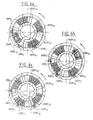
- FIGS. 4, 6a and 6d The operation of the SEI drive system according to the invention which is illustrated by FIGS. 4, 6a and 6d is described below.
- the winding pairs BOBI 1,1 - BOBI 1,2 , B O BI 2.1 -BOBI 2,2 , BOBI 3.1 - BOBI 3.2 are electrically connected so that the forces generated by the passage of the direct current I in the conductors forming each of the two windings of a pair, are added together.
- the two radial branches of the same winding for example, the two branches BR jl and BRj2 of the winding BOBI j in Figure 4, we see that the force to which the winding will be subjected will be maximum when the latter is simultaneously opposite two successive magnetic sectors of opposite polarity, each of the two radial branches being opposite a same sector of determined magnetic polarity.
- the branch BR j2 is completely opposite the magnetic sector SM 4
- the branch BR jl is completely opposite the magnetic sector SM 3 .
- the currents flowing in each of these two branches BR jl and BR j2 are in opposite directions (see for example FIG. 5 where the direction of flow of the current in each of the radial branches has been shown of the different windings BOBI 1.1 to BOBI 3.2 )
- the forces exerted on the two magnetic sectors of opposite polarity SM 4 and SM 3 of the inductor are added.
- a pair of windings is therefore supplied with current I when the two radial branches of each of these are simultaneously opposite two successive magnetic sectors of opposite magnetic polarity.
- the pair of windings BOBI 3.1 - BOBI 3.2 is supplied with current when the inductor and this pair occupy the relative position indicated in Figure 6a
- the pair of windings BOBI 1.1 -BOBI 1.2 is supplied with current when the inductor and this last pair are in the relative position occupied in FIG. 6b
- the pair of windings BOBI 2.1 -BOBI 2.2 is supplied with current when the inductor and this pair occupy the relative position shown in Figure 6c.
- the table indicates, for each of FIGS. 6a, 6b and 6c, the logic output signal of the sensors CAMA 1 , CAMA 2 , CAMA3 and which pair of windings is supplied with current as a function of the logic output signal of these sensors.
- the logic output signals from the sensors CAMA l to CAMA3 are respectively 0.0.1 and the pair of windings supplied with current I is the pair BOBI 3.1 -BOBI 3.2 , and so on.
Landscapes
- Engineering & Computer Science (AREA)
- Power Engineering (AREA)
- Rotational Drive Of Disk (AREA)
- Connection Of Motors, Electrical Generators, Mechanical Devices, And The Like (AREA)
Applications Claiming Priority (2)
| Application Number | Priority Date | Filing Date | Title |
|---|---|---|---|
| FR8515719 | 1985-10-23 | ||
| FR8515719A FR2588991A1 (fr) | 1985-10-23 | 1985-10-23 | Systeme d'entrainement en rotation d'au moins un disque magnetique et moteur electrique inclus dans ce systeme |
Publications (1)
| Publication Number | Publication Date |
|---|---|
| EP0223676A1 true EP0223676A1 (de) | 1987-05-27 |
Family
ID=9324114
Family Applications (1)
| Application Number | Title | Priority Date | Filing Date |
|---|---|---|---|
| EP86402367A Withdrawn EP0223676A1 (de) | 1985-10-23 | 1986-10-22 | Rotierende Laufwerkanlage für mindestens eine magnetische Platte und elektrischer Motor in dieser Anlage einbegriffen |
Country Status (2)
| Country | Link |
|---|---|
| EP (1) | EP0223676A1 (de) |
| FR (1) | FR2588991A1 (de) |
Cited By (1)
| Publication number | Priority date | Publication date | Assignee | Title |
|---|---|---|---|---|
| EP0730336A3 (de) * | 1995-03-03 | 1997-06-25 | Minebea Co Ltd | Bürstenloser Gleichstrommotor |
Families Citing this family (2)
| Publication number | Priority date | Publication date | Assignee | Title |
|---|---|---|---|---|
| FR2627313B1 (fr) * | 1988-02-12 | 1994-08-05 | Mecanique Magnetique Sa | Dispositif de suspension et d'entrainement de disques de memoire d'ordinateur |
| JPH03222149A (ja) * | 1990-01-29 | 1991-10-01 | Sony Corp | 記録媒体ディスク駆動装置 |
Citations (2)
| Publication number | Priority date | Publication date | Assignee | Title |
|---|---|---|---|---|
| FR1318926A (fr) * | 1962-03-12 | 1963-02-22 | Haydon Instr Company | Dispositif électrique tournant, comme un moteur ou une génératrice |
| EP0086682A1 (de) * | 1982-02-11 | 1983-08-24 | COMPAGNIE INTERNATIONALE POUR L'INFORMATIQUE CII - HONEYWELL BULL (dite CII-HB) | Plattenspeicher mit einer abnehmbaren Magnetplatten-Kassette und Magnetplattenkassette |
Family Cites Families (2)
| Publication number | Priority date | Publication date | Assignee | Title |
|---|---|---|---|---|
| JPS58200479A (ja) * | 1982-05-19 | 1983-11-22 | Matsushita Electric Ind Co Ltd | デイスク状記録媒体の回転駆動装置 |
| JPS59175079A (ja) * | 1983-03-22 | 1984-10-03 | Matsushita Electric Ind Co Ltd | デイスクのクランプ装置 |
-
1985
- 1985-10-23 FR FR8515719A patent/FR2588991A1/fr active Pending
-
1986
- 1986-10-22 EP EP86402367A patent/EP0223676A1/de not_active Withdrawn
Patent Citations (2)
| Publication number | Priority date | Publication date | Assignee | Title |
|---|---|---|---|---|
| FR1318926A (fr) * | 1962-03-12 | 1963-02-22 | Haydon Instr Company | Dispositif électrique tournant, comme un moteur ou une génératrice |
| EP0086682A1 (de) * | 1982-02-11 | 1983-08-24 | COMPAGNIE INTERNATIONALE POUR L'INFORMATIQUE CII - HONEYWELL BULL (dite CII-HB) | Plattenspeicher mit einer abnehmbaren Magnetplatten-Kassette und Magnetplattenkassette |
Non-Patent Citations (4)
| Title |
|---|
| IBM TECHNICAL DISCLOSURE BULLETIN, vol. 19, no. 12, mai 1977, pages 4722-4723, New York, US; J.L. BECK et al.: "Hub assembly for flexible disk media" * |
| IBM TECHNICAL DISCLOSURE BULLETIN, vol. 19, no. 7, décembre 1976, pages 2684, 2685, New York, US; F.K. KING et al.: "Cartridge for magnetic disk" * |
| PATENTS ABSTRACTS OF JAPAN, vol. 8, no. 51 (P-259)[1488] 8 mars 1984, & JP - A - 58 200 479 (MATSUSHITA DENKI SANGYO K.K.) 22-11-1983 * |
| PATENTS ABSTRACTS OF JAPAN, vol.9, no. 33 (P-334) [1756] 13 février 1985, & JP - A - 59 175 079 (MATSUSHITA DENKI SANGYO K.K.) 03-10-1984 * |
Cited By (1)
| Publication number | Priority date | Publication date | Assignee | Title |
|---|---|---|---|---|
| EP0730336A3 (de) * | 1995-03-03 | 1997-06-25 | Minebea Co Ltd | Bürstenloser Gleichstrommotor |
Also Published As
| Publication number | Publication date |
|---|---|
| FR2588991A1 (fr) | 1987-04-24 |
Similar Documents
| Publication | Publication Date | Title |
|---|---|---|
| EP1269133B1 (de) | Positionssensor, insbesondere zur messung des drehmoments einer lenksäule | |
| FR2565045A1 (fr) | Dispositif pour la detection de la position angulaire du rotor d'une machine electrique tournante a commutation electronique | |
| EP0284487B1 (de) | Magnetische Lagerung eines Körpers bei gleichzeitiger Zentrierung bezüglich mindestens einer Achse | |
| FR2524090A1 (fr) | Dispositif de suspension magnetique pour roue d'inertie | |
| CH643330A5 (fr) | Procede et dispositif d'equilibrage d'un corps tournant a suspension magnetique radiale passive et axiale active et/ou d'orientation de son axe de rotation. | |
| FR2568377A1 (fr) | Capteur de vitesse a effet hall incorpore dans une machine tournante | |
| FR2844591A1 (fr) | Dispositif de determination du deplacement d'un arbre | |
| CA1129928A (fr) | Moteur electrique synchrone a tres faible inertie rotorique a mouvement conique equilibre | |
| FR2588991A1 (fr) | Systeme d'entrainement en rotation d'au moins un disque magnetique et moteur electrique inclus dans ce systeme | |
| EP0312464B1 (de) | Elektrische Maschine insbesondere mit radialen Luftspalten | |
| FR2742497A1 (fr) | Palier magnetique a actionneurs et capteurs alternes | |
| EP0800055A1 (de) | Linear- und Winkelpositionssensor | |
| FR2618616A1 (fr) | Machine electrique a couple d'entrainement et/ou de positionnement eleve | |
| EP0884823B1 (de) | Elektromagnetische Antriebsvorrichtung mit beweglichem Permanentmagnet | |
| EP0038744B1 (de) | Schrittmotor, besonders für eine elektronische Uhr | |
| FR2609583A3 (fr) | Generatrice sans balai comprenant un ensemble inducteur a elements polaires a griffes | |
| EP0965724B1 (de) | Antriebsvorrichtung einer in zwei Richtungen drehbaren rohrförmigen Walze, Rolladenwalze mit einer derartigen Antriebsvorrichtung, Rolladen mit einer derartigen Walze | |
| FR2588990A1 (fr) | Dispositif a bras de pivotement, muni d'une unite d'entrainement electromagnetique | |
| FR2557700A1 (fr) | Accelerometre angulaire | |
| WO2000058976A1 (fr) | Procede pour la determination de la position d'un organe mobile dans au moins un entrefer principal d'un actionneur electromagnetique | |
| WO1998035167A1 (fr) | Palier magnetique rotatif a centrage actif le long de l'axe de rotation et a faible cout | |
| FR2493981A1 (fr) | Dispositif detecteur de la position d'un organe rotatif | |
| FR2497571A1 (fr) | Detecteur de position pour rotor de machine electrique | |
| FR3089714A1 (fr) | Rotor comprenant un détecteur magnétique de paramètre de rotation du rotor | |
| FR2892868A1 (fr) | Machine electrique a sondes a effet hall. |
Legal Events
| Date | Code | Title | Description |
|---|---|---|---|
| PUAI | Public reference made under article 153(3) epc to a published international application that has entered the european phase |
Free format text: ORIGINAL CODE: 0009012 |
|
| AK | Designated contracting states |
Kind code of ref document: A1 Designated state(s): DE FR GB IT NL SE |
|
| 17P | Request for examination filed |
Effective date: 19870613 |
|
| 17Q | First examination report despatched |
Effective date: 19890329 |
|
| STAA | Information on the status of an ep patent application or granted ep patent |
Free format text: STATUS: THE APPLICATION IS DEEMED TO BE WITHDRAWN |
|
| 18D | Application deemed to be withdrawn |
Effective date: 19890809 |
|
| RIN1 | Information on inventor provided before grant (corrected) |
Inventor name: DUPONT, JEAN |