EP0223682B1 - Gerät zur Schallkartographie - Google Patents
Gerät zur Schallkartographie Download PDFInfo
- Publication number
- EP0223682B1 EP0223682B1 EP86402414A EP86402414A EP0223682B1 EP 0223682 B1 EP0223682 B1 EP 0223682B1 EP 86402414 A EP86402414 A EP 86402414A EP 86402414 A EP86402414 A EP 86402414A EP 0223682 B1 EP0223682 B1 EP 0223682B1
- Authority
- EP
- European Patent Office
- Prior art keywords
- mapping
- recording
- sound level
- sound
- coordinates
- Prior art date
- Legal status (The legal status is an assumption and is not a legal conclusion. Google has not performed a legal analysis and makes no representation as to the accuracy of the status listed.)
- Expired
Links
- 238000013507 mapping Methods 0.000 title claims abstract description 48
- 238000010200 validation analysis Methods 0.000 claims abstract description 9
- 238000005070 sampling Methods 0.000 claims abstract description 6
- 238000012360 testing method Methods 0.000 claims description 35
- 238000005259 measurement Methods 0.000 claims description 24
- 230000015654 memory Effects 0.000 claims description 16
- 238000001514 detection method Methods 0.000 description 12
- 238000003860 storage Methods 0.000 description 10
- 238000010586 diagram Methods 0.000 description 6
- 230000006870 function Effects 0.000 description 5
- 238000009434 installation Methods 0.000 description 3
- 238000000034 method Methods 0.000 description 3
- 230000001960 triggered effect Effects 0.000 description 3
- 230000000694 effects Effects 0.000 description 2
- 238000011065 in-situ storage Methods 0.000 description 2
- 230000004044 response Effects 0.000 description 2
- 238000007493 shaping process Methods 0.000 description 2
- 241000135309 Processus Species 0.000 description 1
- 230000003213 activating effect Effects 0.000 description 1
- 230000001154 acute effect Effects 0.000 description 1
- 230000003321 amplification Effects 0.000 description 1
- 238000006243 chemical reaction Methods 0.000 description 1
- 238000011161 development Methods 0.000 description 1
- 230000008030 elimination Effects 0.000 description 1
- 238000003379 elimination reaction Methods 0.000 description 1
- 230000010354 integration Effects 0.000 description 1
- 230000005865 ionizing radiation Effects 0.000 description 1
- 239000004973 liquid crystal related substance Substances 0.000 description 1
- 238000004519 manufacturing process Methods 0.000 description 1
- 238000003199 nucleic acid amplification method Methods 0.000 description 1
- 230000003449 preventive effect Effects 0.000 description 1
- 230000002035 prolonged effect Effects 0.000 description 1
- 239000004065 semiconductor Substances 0.000 description 1
- 230000005236 sound signal Effects 0.000 description 1
- 238000013518 transcription Methods 0.000 description 1
- 230000035897 transcription Effects 0.000 description 1
- 238000012546 transfer Methods 0.000 description 1
- 238000011144 upstream manufacturing Methods 0.000 description 1
- 238000012795 verification Methods 0.000 description 1
- 230000003936 working memory Effects 0.000 description 1
Images




Classifications
-
- G—PHYSICS
- G01—MEASURING; TESTING
- G01H—MEASUREMENT OF MECHANICAL VIBRATIONS OR ULTRASONIC, SONIC OR INFRASONIC WAVES
- G01H3/00—Measuring characteristics of vibrations by using a detector in a fluid
- G01H3/10—Amplitude; Power
- G01H3/12—Amplitude; Power by electric means
Definitions
- the present invention relates to a sound mapping device.
- Document US-A-4,307,385 relates to a noise level and dose measurement device intended to protect an individual in harmful or dangerous noise level conditions. Although this device allows the triggering of an alarm system in relation to a reference threshold level, this device cannot perform the mapping function since the spatial reference for measuring the noise level is indeed the individual himself and not the endmif where it is located.
- the present invention aims to remedy the aforementioned drawbacks by the implementation of a sound mapping device.
- Another object of the present invention is the implementation of a sound mapping device with a very high degree of reliability and fidelity.
- Another object of the present invention is the implementation of a portable sound mapping device and implementation, which can be performed by a single operator.
- the sound mapping device object of the present invention, is remarkable in that it comprises means of display by an operator of the coordinates representative of each point of the sound level survey space, the coordinates being generated in the form digitized and means for displaying the sound level at said point in the sound level reading space. Means for conditional recording of the sound level and the coordinates are also provided, the coordinates and the corresponding sound level, constituting for each survey point the sound mapping variable and all the mapping variables constituting the mapping information. memorized.
- the invention finds application in all industrial or urban sites or sites, in particular in all industrial sites for the production of energy by rotating machines, as well as in industrial sites with a high noise environment in which tests in an anechoid chamber must be performed.
- the device of the invention comprises, with means for detecting sound level in digitized form, display means, denoted 1, by an operator, coordinates representative of each point of the level reading space. sound. These coordinates are generated in digitized form and can, of course, constitute coordinates of any kind such as Cartesian coordinates, polar coordinates, or even a simple coded reference representative of a determined location in the sound level survey space.
- display means 1 in which two values X, Y are capable of representing any point in a plane space of sound level reading.
- the device of the invention may include a system for displaying and entering coordinates, by an operator, comprising three inputs with a view, if necessary, to recording the sound level in a space for three dimensions.
- the means 1 of display and of introduction by an operator of the above coordinates can be constituted by a system of coding wheels 10, 11, followed by a digitization system not shown in the figure. 1, or by any similar system.
- the device of the invention further comprises means 2 for displaying the sound level at the point of the sound level reading space.
- the means 2 for displaying the sound level are shown so as to include displays 20 and 21 directly connected to the aforementioned sound level detection means, these displays making it possible, from the analog signal resulting from the level detection sound, a display of the sound levels detected after linear detection and / or subject to weighting, as will be described later in the description.
- the device according to the invention further comprises means 3 for conditional recording of the detected sound level and the aforementioned coordinates, the coordinates and the corresponding sound level constituting for each survey point the sound mapping variable and all of the sound mapping variables constituting the stored sound information.
- the means 2 for displaying the sound level in which digital display units 22, 23, 24, 25 are provided, these units digital display being connected to means 3 for conditional recording of the sound level and the coordinates.
- the digital display units can be constituted in a nonlimiting manner by liquid crystal display cells or the like.
- the device which is the subject of the invention will be noted below.
- the device continuously performs and displays at the aforementioned displays 20 and 21, the measurement of the noise levels or linear and weighted sound levels.
- the analog indication on the aforementioned displays preferably arranged on the front of the device, allows the operator to check these levels and possibly adjust the level detected by means of an attenuating system.
- the operator then displays, by means of display 1, the coordinates of the measurement point, which are entered in digitized form in the conditional recording means.
- the operator then commands the triggering of a measurement proper and the device i f indicates at the four digital display units 22, 23, 24, 25, the four values corresponding to the weighted sound level value, linear, and at the coordinates actually entered.
- the operator can thus globally check the validity of the four parameters before registering them properly.
- conditional recording means 3 are deemed to include sound level detection means in digital form denoted 30, an interface 31 capable of ensuring the link between the circuits or detection means 30, 1 delivering the mapping variable and the recording circuits proper, a central management unit 32 of the mapping variables receiving these via the 'interface 31 and a command register 33 and storage 35 of the aforementioned variables constituting the actual recording circuits.
- conditional recording means 3 comprise a test control unit 34, provided with a keyboard from which all of the control operations can be carried out by the operator. In FIG. 1, the keyboard is represented by the arrows adjacent to block 34.
- the sound level detection means 30 may comprise a microphone 301 connected to an amplifier 302, which delivers the detected sound level signal to two parallel channels.
- the first chain comprises a filter 308 making it possible to perform frequency weighting, for example of the detected signal, a circuit 307 for measuring the effective value of the signal delivered by the filter 308, therefore after weighting, and an analog / digital converter 305, delivering the digitized signal corresponding to the interface 31.
- the RMS measurement circuit 307 directly controls the display 21.
- the filter 308 inserted in the first aforementioned chain can be constituted by any filter or by a filter bank capable of operating a weighting defined as A, B, C weighting or even D weighting in the case of the same noise level caused by aircraft, by French standard NF S 31-009.
- the second detection chain comprises a circuit for measuring the effective value of the sound level 306, receiving the signal delivered by the amplifier 302 and an analog / digital converter 304, itself delivering the corresponding signal digitized at the interface 31.
- the second detection chain thus allows the development of a detected sound level signal corresponding to the LIN characteristic of constant frequency response, as defined by the aforementioned French standard.
- An attenuator 303 makes it possible to adjust the amplification level of the amplifier 302, the attenuation value being of course transmitted to the interface 31.
- the interface 31 comprises a data muftiplexer 310, receiving the signal representative of the detected sound level in digital form and the value signal of the coordinates of the survey point considered also in digital form. These two digital signals are transmitted to the multiplexer 310 by the BUS D1 - D4 shown in FIG. 2.
- the muftiplexer 310 can be constituted by any digital multiplexer, normally available commercially, with four input bits and sixteen parallel output bits and reciprocally.
- the multiplexer 310 is also connected to the detection circuit 30 by means of a BUS D delivering to the muftiplexer the effective values of the sound level applied to the displays 20 and 21, in digitized form, and by a control bus denoted 1 - 2 , allowing the selection of the card or analog chain of linear or weighted detection.
- the multiplexer 310 is also connected to the display means 1 by a control BUS denoted 4 - 5, to the central unit 32 via a first address control BUS denoted DA1 - DA4 and by a second data BUS after multiplexing noted D01 - D04.
- the displays 22, 23, 24, 25 are also connected to the two aforementioned BUSes.
- the storage register 33 is preferably constituted by a control register 330 connected to the address control BUS DA1 - DA4 and to the data BUS after multiplexing D01 - D04, as well as a storage and test unit 331 connected on the one hand to the control register 330 by a control BUS noted 1 - 2 - 3, the control register 330 and the storage and test unit 331 being controlled by the central unit 32, via an order control BUS noted 00 ... 013.
- the storage unit 331 receives the mapping variables on command from the command register 330 via the BUS D1 - D4.
- the storage and test unit 331 is also connected by an analog / digital conversion trigger connection to the detection circuit 30, command denoted C A / D , to the muftiplexer 310 by a BUS for activating the memory circuits to the power-up of the device, BUS noted 3, to the test control unit 34, to the central unit by a command connection JC allowing the validation of the central unit and by an F1 command to this same central unit allowing the command to properly store the mapping variables.
- the command register 330 may comprise, by way of example, a set of memory circuits denoted 3301, 3302, 3303, 3304, 3305 and 3306, which are supplied directly in parallel by the BUS D01 - D04.
- the aforementioned memories are loaded from the address commands DA1 - DA2, a recording and reading order being given to the aforementioned memories on an R / W order via logic gates 3310, 3311, 3312, on coincidence with the order commands issued by the order control BUS 01, 02, 03, via a shaping circuit 3313.
- Buffer memories 3307, 3308, 3309 make it possible to store, on the selection order, said card selection order issued by the BUS 012-015, the control information delivered by the control BUS 1 - 2 - 3 to the storage and test unit 331.
- the aforementioned storage and test unit 331 comprises a logic control unit 3312, controlled from a control multiplexer 3311, receiving the command F1 already mentioned from the unit central management 32.
- the storage and test unit 331 further comprises an up-down counter 3313 controlled by the control logic unit, and an electrically programmable read-only memory 3314 connected to the counter 3313 and to the control logic 3312.
- the ROM type memory is intended to memorize the mapping variables, so as to constitute the mapping information.
- the function of the up-down counter, prior to each actual recording, is to increment or decrement the addresses at which the mapping variables will actually be recorded.
- the electrically programmable read-only memory 3314 receives the data and the addresses constituting the mapping variables by means of the aforementioned BUS D1 - D4, and of the BUS issuing from the control register BUS 1 - 2 - 3.
- the storage and test unit 330 comprises a test multiplexer 3310, controlled by the central unit via the control BUS 012-015 and connected to the control logic 3312 and to the control muftiplexer 3311.
- the multiplexer of test 3310 makes it possible to develop the signal JC selecting the type of order generated by the central management unit 32.
- the keyboard of the test unit 34 is direct connected to the test muftiplexer 3310.
- the control logic 3312 has the function of formatting and formatting of the data prior to its recording.
- the control logic can be constituted by circuits of conventional type, which will not be described since they do not fall within the object of the present invention.
- the test muftiplexer 3310 makes it possible, in particular to find the address of the last recorded map value, which allows, in particular, the comparison of the current map variable after validation of the record by the operator to the last record made in ROM 3314.
- the read-only memory 3314 can be constituted by a plug-in cassette type unit authorizing 2000 measurements of four parameters coded according to a binary coded decimal code on 10 4 points for example, and with a capacity of 128 Kb .
- plug-in units are marketed in particular in France under the trademark LERTIE and can be advantageously incorporated into the device of the invention.
- the means 2 for displaying the sound level comprise digital display units 22, 23, 24, 25 connected to the data bus D01 - D04 and to the address control BUS DA1 - DA4, via digital doors 220, 230, 240, 250 respectively.
- the selection of the display on one of the aforementioned displays is carried out from the BUS of order command DO - D1 and an intermediate display selection circuit 280, controlling the doors 220, 230, 240, 250 and the selection of the digits to be displayed on each selected display is carried out on command of the order R / W, via a digit selection circuit 260, transmitting the addresses of BUS DA1 - DA4 in coincidence with the data of BUS D01 - D04.
- a shaping circuit 270 is connected upstream of the digit selection circuit 260.
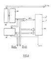
- Figure 6 shows the schematic layout of the elements constituting the central unit.
- this can include a microprocessor 320 delivering the signal F1 and receiving the aforementioned JC signal, the microprocessor 320 also delivering the R / W signal.
- This microprocessor can be constituted by a microprocessor sold under the reference NS 57 109 by the company National Semiconductors.
- the microprocessor 320 is associated, conventionally, with an addressable memory 321, constituting for the microprocessor 320, the central memory or working memory.
- a read-only memory 321 associated with its counter-pointer 322 is connected on the one hand to the microprocessor 320 and to the addressable memory 321.
- the microprocessor is connected to the data bus D01 - D04 and to the BUS DA1 - DA4 address to which the addressable memory 321 is also connected.
- the read-only memory 321 comprises a program for managing the apparatus or device of the invention, which is driven by the microprocessor 320 and transmitted by the control BUS 00 - 015.
- switching on the device causes a program to run in which, after resetting the microprocessor 320, a series of tests are successively carried out, a first test relating to the state of charge of the device supply battery, a second test relating to the existence or non-existence of the measurement control order given by the operator, a third test relating to the reading of the displayed values, which in the presence of the introduction of the coordinates of the measurement point allows the control of the validated mapping variable.
- an order to read the last recorded coordinate is executed, then the system is returned to the recording test position.
- a recording control test is also carried out after this, this test can consist of a comparison of the value to be recorded coded and the value actually recorded coded according to the same code.
- a positive test allows the return to the initial state, a negative test allows the triggering of an alarm and the verification of the presence or the effective absence of the plug-in cassette in its housing.
- the reading function can be carried out in two ways which can be chosen using a switch by the operator.
- the device In a first position of the switch, the device re-reads the last measurement that was recorded, this allows the operator to possibly check the last measurement point and also to reset after a prolonged recording stop.
- the device In the other position of the switch, the device reads back linear and weighted measurements, relating to a point of coordinates X and Y, by displaying this pair of values on the corresponding coding wheels.
- This acquisition of 25 effective values is carried out in so-called FAST mode, that is to say with a sufficient sampling frequency, as a function of the maximum possible effective frequency of the sound signal whose level is to be measured.
- FAST mode that is to say with a sufficient sampling frequency, as a function of the maximum possible effective frequency of the sound signal whose level is to be measured.
- an average of all these 25 values is taken, and the value of the sound level corresponding to the measurement point is defined as the logarithm of the average previously obtained.
- the position of the attenuator 303 is then taken into account by summation or integration of the value of the signal representative of this attenuation transmitted to the interface 31 to define the value of the mapping variable actually displayed.
- the device of the invention as it has been produced satisfies all the specifications of the aforementioned French standard relating to acoustic recording apparatus or sound level meter of classes 2 and 3, this standard being in itself compliant and in technical accordance with publication 651 of the International Electric Committee.
Landscapes
- Physics & Mathematics (AREA)
- General Physics & Mathematics (AREA)
- Measurement Of Mechanical Vibrations Or Ultrasonic Waves (AREA)
- Stringed Musical Instruments (AREA)
- Handcart (AREA)
- Soundproofing, Sound Blocking, And Sound Damping (AREA)
Claims (8)
Priority Applications (1)
| Application Number | Priority Date | Filing Date | Title |
|---|---|---|---|
| AT86402414T ATE48474T1 (de) | 1985-10-30 | 1986-10-28 | Geraet zur schallkartographie. |
Applications Claiming Priority (2)
| Application Number | Priority Date | Filing Date | Title |
|---|---|---|---|
| FR8516152 | 1985-10-30 | ||
| FR8516152A FR2589584B1 (fr) | 1985-10-30 | 1985-10-30 | Dispositif de cartographie sonore |
Publications (2)
| Publication Number | Publication Date |
|---|---|
| EP0223682A1 EP0223682A1 (de) | 1987-05-27 |
| EP0223682B1 true EP0223682B1 (de) | 1989-12-06 |
Family
ID=9324372
Family Applications (1)
| Application Number | Title | Priority Date | Filing Date |
|---|---|---|---|
| EP86402414A Expired EP0223682B1 (de) | 1985-10-30 | 1986-10-28 | Gerät zur Schallkartographie |
Country Status (7)
| Country | Link |
|---|---|
| EP (1) | EP0223682B1 (de) |
| CN (1) | CN1016818B (de) |
| AT (1) | ATE48474T1 (de) |
| CA (1) | CA1268246A (de) |
| DE (1) | DE3667328D1 (de) |
| ES (1) | ES2012054B3 (de) |
| FR (1) | FR2589584B1 (de) |
Families Citing this family (2)
| Publication number | Priority date | Publication date | Assignee | Title |
|---|---|---|---|---|
| FR2831956B1 (fr) * | 2001-11-02 | 2004-01-23 | Boubezari Mohammed | Dispositif portatif de mesure des courbes d'isophonie d'une source de bruit par effet de masque acoustique et son procede d'utlisation |
| US9114798B1 (en) | 2012-12-12 | 2015-08-25 | Hydro-Gear Limited Partnership | Electric actuator for drive apparatus |
Family Cites Families (4)
| Publication number | Priority date | Publication date | Assignee | Title |
|---|---|---|---|---|
| US4307385A (en) * | 1978-11-22 | 1981-12-22 | Sue Ann Evans | Noise monitoring apparatus |
| FR2473174A1 (fr) * | 1980-01-02 | 1981-07-10 | Cormier Gilles | Sonometre dosimetre miniature |
| GB2116713A (en) * | 1982-03-09 | 1983-09-28 | Tecalemit Electronics Ltd | Vibration monitoring apparatus |
| US4554639A (en) * | 1983-04-06 | 1985-11-19 | E. I. Du Pont De Nemours And Company | Audio dosimeter |
-
1985
- 1985-10-30 FR FR8516152A patent/FR2589584B1/fr not_active Expired
-
1986
- 1986-10-28 EP EP86402414A patent/EP0223682B1/de not_active Expired
- 1986-10-28 DE DE8686402414T patent/DE3667328D1/de not_active Expired - Lifetime
- 1986-10-28 CA CA000521632A patent/CA1268246A/fr not_active Expired - Lifetime
- 1986-10-28 AT AT86402414T patent/ATE48474T1/de active
- 1986-10-28 ES ES86402414T patent/ES2012054B3/es not_active Expired - Lifetime
- 1986-10-29 CN CN86107241A patent/CN1016818B/zh not_active Expired
Also Published As
| Publication number | Publication date |
|---|---|
| ES2012054B3 (es) | 1990-03-01 |
| CA1268246A (fr) | 1990-04-24 |
| CN86107241A (zh) | 1987-06-10 |
| CN1016818B (zh) | 1992-05-27 |
| FR2589584B1 (fr) | 1988-04-01 |
| DE3667328D1 (de) | 1990-01-11 |
| ATE48474T1 (de) | 1989-12-15 |
| FR2589584A1 (fr) | 1987-05-07 |
| EP0223682A1 (de) | 1987-05-27 |
Similar Documents
| Publication | Publication Date | Title |
|---|---|---|
| EP0072270B1 (de) | Bestürzungsaufzeichnungssystem | |
| FR2696565A1 (fr) | Collecte et traitement automatisés d'échantillons environnementaux. | |
| FR2767201A1 (fr) | Dosimetre personnel de rayonnement | |
| CA2064019C (fr) | Procede pour la surveillance d'equipements et dispositif pour la mise en oeuvre de ce procede | |
| EP0223682B1 (de) | Gerät zur Schallkartographie | |
| FR2734386A1 (fr) | Dispositif et procede de communication par infrarouge entre un utilisateur et un appareil telecommandable | |
| FR2797958A1 (fr) | Procede et dispositif de test du fonctionnement d'une unite electronique par simulation et installation de test d'unite a embarquer sur un materiel ferroviaire ou un vehicule electrique | |
| EP0543698B1 (de) | Vorrichtung zur Benutzung von Fehlerinformationen eines Einzel- oder Mehrrechnersystems eines Flugzeuges | |
| EP0813068B1 (de) | Anordnung zur Aufspürung und Lokalisierung von Fehlern in der elektromagnetischen Abschirmung eines Systems | |
| FR2657793A1 (fr) | Appareil de centrifugation a rotor amovible et a moyens d'identification des rotors. | |
| JP2002296118A (ja) | 光子相関計 | |
| EP0118919B1 (de) | Verfahren und Gerät zum Umwandeln spektraler und lichtintensiver Werte unmittelbar in digitale Daten | |
| EP0097555B1 (de) | System zur Aufnahme von auf einem Datenträger eingeschriebenen Daten | |
| EP2146188A2 (de) | Verfahren zum Entdecken einer Störung an einem Analogsensor und Erkennungsvorrichtung zur Umsetzung dieses Verfahrens | |
| EP0375546B1 (de) | Verfahren zur Störung der Tastenerkennung einer unkodierten Tastatur und Schaltung zur Ausführung des Verfahrens | |
| WO1994005119A1 (fr) | Dispositif de controle et de maintenance a distance de reseaux cables | |
| EP1372074A1 (de) | System und Verfahren zur Ereignisverwaltung | |
| EP0279738A1 (de) | Vorrichtung zur Prüfung einer elektrischen Schaltung und diese Vorrichtung enthaltende Schaltung | |
| EP0208673B1 (de) | Automatische Prüfvorrichtung | |
| EP0327446A1 (de) | Digitaler Komparator, Digital-Ratiometer und Amplituden-Analysator mit solchen Ratiometern | |
| EP0678814A1 (de) | Verfahren und Einrichtung zum Verdichten abzuspeichernder Information und zum Verarbeiten der verdichteten Information | |
| EP1051689B1 (de) | Chipkarte mit hardwareübertragungsschaltung | |
| FR2552552A1 (fr) | Dispositif de constitution d'un histogramme en temps reel | |
| EP0636984B1 (de) | Verfahren und Vorrichtung zur Überwachung der Daten eines Rechners | |
| FR2596521A1 (fr) | Procede et dispositif de controle automatique de systemes tournants, notamment de roulements |
Legal Events
| Date | Code | Title | Description |
|---|---|---|---|
| PUAI | Public reference made under article 153(3) epc to a published international application that has entered the european phase |
Free format text: ORIGINAL CODE: 0009012 |
|
| AK | Designated contracting states |
Kind code of ref document: A1 Designated state(s): AT BE CH DE ES GB IT LI LU NL SE |
|
| 17P | Request for examination filed |
Effective date: 19870504 |
|
| 17Q | First examination report despatched |
Effective date: 19880614 |
|
| GRAA | (expected) grant |
Free format text: ORIGINAL CODE: 0009210 |
|
| AK | Designated contracting states |
Kind code of ref document: B1 Designated state(s): AT BE CH DE ES GB IT LI LU NL SE |
|
| PG25 | Lapsed in a contracting state [announced via postgrant information from national office to epo] |
Ref country code: SE Effective date: 19891206 Ref country code: NL Effective date: 19891206 Ref country code: AT Effective date: 19891206 |
|
| REF | Corresponds to: |
Ref document number: 48474 Country of ref document: AT Date of ref document: 19891215 Kind code of ref document: T |
|
| ITF | It: translation for a ep patent filed | ||
| REF | Corresponds to: |
Ref document number: 3667328 Country of ref document: DE Date of ref document: 19900111 |
|
| GBT | Gb: translation of ep patent filed (gb section 77(6)(a)/1977) | ||
| NLV1 | Nl: lapsed or annulled due to failure to fulfill the requirements of art. 29p and 29m of the patents act | ||
| PLBE | No opposition filed within time limit |
Free format text: ORIGINAL CODE: 0009261 |
|
| STAA | Information on the status of an ep patent application or granted ep patent |
Free format text: STATUS: NO OPPOSITION FILED WITHIN TIME LIMIT |
|
| PG25 | Lapsed in a contracting state [announced via postgrant information from national office to epo] |
Ref country code: LU Free format text: LAPSE BECAUSE OF NON-PAYMENT OF DUE FEES Effective date: 19901031 |
|
| 26N | No opposition filed | ||
| ITTA | It: last paid annual fee | ||
| REG | Reference to a national code |
Ref country code: GB Ref legal event code: IF02 |
|
| PGFP | Annual fee paid to national office [announced via postgrant information from national office to epo] |
Ref country code: DE Payment date: 20031008 Year of fee payment: 18 |
|
| PGFP | Annual fee paid to national office [announced via postgrant information from national office to epo] |
Ref country code: CH Payment date: 20031013 Year of fee payment: 18 |
|
| PGFP | Annual fee paid to national office [announced via postgrant information from national office to epo] |
Ref country code: GB Payment date: 20031021 Year of fee payment: 18 |
|
| PGFP | Annual fee paid to national office [announced via postgrant information from national office to epo] |
Ref country code: BE Payment date: 20031031 Year of fee payment: 18 |
|
| PGFP | Annual fee paid to national office [announced via postgrant information from national office to epo] |
Ref country code: ES Payment date: 20031118 Year of fee payment: 18 |
|
| PG25 | Lapsed in a contracting state [announced via postgrant information from national office to epo] |
Ref country code: GB Free format text: LAPSE BECAUSE OF NON-PAYMENT OF DUE FEES Effective date: 20041028 |
|
| PG25 | Lapsed in a contracting state [announced via postgrant information from national office to epo] |
Ref country code: ES Free format text: LAPSE BECAUSE OF NON-PAYMENT OF DUE FEES Effective date: 20041029 |
|
| PG25 | Lapsed in a contracting state [announced via postgrant information from national office to epo] |
Ref country code: LI Free format text: LAPSE BECAUSE OF NON-PAYMENT OF DUE FEES Effective date: 20041031 Ref country code: CH Free format text: LAPSE BECAUSE OF NON-PAYMENT OF DUE FEES Effective date: 20041031 Ref country code: BE Free format text: LAPSE BECAUSE OF NON-PAYMENT OF DUE FEES Effective date: 20041031 |
|
| BERE | Be: lapsed |
Owner name: *ELECTRICITE DE FRANCE SERVICE NATIONAL Effective date: 20041031 |
|
| PG25 | Lapsed in a contracting state [announced via postgrant information from national office to epo] |
Ref country code: DE Free format text: LAPSE BECAUSE OF NON-PAYMENT OF DUE FEES Effective date: 20050503 |
|
| GBPC | Gb: european patent ceased through non-payment of renewal fee |
Effective date: 20041028 |
|
| REG | Reference to a national code |
Ref country code: CH Ref legal event code: PL |
|
| PG25 | Lapsed in a contracting state [announced via postgrant information from national office to epo] |
Ref country code: IT Free format text: LAPSE BECAUSE OF NON-PAYMENT OF DUE FEES;WARNING: LAPSES OF ITALIAN PATENTS WITH EFFECTIVE DATE BEFORE 2007 MAY HAVE OCCURRED AT ANY TIME BEFORE 2007. THE CORRECT EFFECTIVE DATE MAY BE DIFFERENT FROM THE ONE RECORDED. Effective date: 20051028 |
|
| REG | Reference to a national code |
Ref country code: ES Ref legal event code: FD2A Effective date: 20041029 |
|
| BERE | Be: lapsed |
Owner name: *ELECTRICITE DE FRANCE SERVICE NATIONAL Effective date: 20041031 |