EP0223707A2 - Kohlenstoffaseraggregat, das die Schwerkraftzuführung zulässt und Verfahren zur Herstellung desselben - Google Patents
Kohlenstoffaseraggregat, das die Schwerkraftzuführung zulässt und Verfahren zur Herstellung desselben Download PDFInfo
- Publication number
- EP0223707A2 EP0223707A2 EP86402525A EP86402525A EP0223707A2 EP 0223707 A2 EP0223707 A2 EP 0223707A2 EP 86402525 A EP86402525 A EP 86402525A EP 86402525 A EP86402525 A EP 86402525A EP 0223707 A2 EP0223707 A2 EP 0223707A2
- Authority
- EP
- European Patent Office
- Prior art keywords
- carbon fiber
- carbon fibers
- working chamber
- loose
- set forth
- Prior art date
- Legal status (The legal status is an assumption and is not a legal conclusion. Google has not performed a legal analysis and makes no representation as to the accuracy of the status listed.)
- Withdrawn
Links
Images

Classifications
-
- D—TEXTILES; PAPER
- D01—NATURAL OR MAN-MADE THREADS OR FIBRES; SPINNING
- D01F—CHEMICAL FEATURES IN THE MANUFACTURE OF ARTIFICIAL FILAMENTS, THREADS, FIBRES, BRISTLES OR RIBBONS; APPARATUS SPECIALLY ADAPTED FOR THE MANUFACTURE OF CARBON FILAMENTS
- D01F9/00—Artificial filaments or the like of other substances; Manufacture thereof; Apparatus specially adapted for the manufacture of carbon filaments
- D01F9/08—Artificial filaments or the like of other substances; Manufacture thereof; Apparatus specially adapted for the manufacture of carbon filaments of inorganic material
- D01F9/12—Carbon filaments; Apparatus specially adapted for the manufacture thereof
-
- D—TEXTILES; PAPER
- D04—BRAIDING; LACE-MAKING; KNITTING; TRIMMINGS; NON-WOVEN FABRICS
- D04H—MAKING TEXTILE FABRICS, e.g. FROM FIBRES OR FILAMENTARY MATERIAL; FABRICS MADE BY SUCH PROCESSES OR APPARATUS, e.g. FELTS, NON-WOVEN FABRICS; COTTON-WOOL; WADDING ; NON-WOVEN FABRICS FROM STAPLE FIBRES, FILAMENTS OR YARNS, BONDED WITH AT LEAST ONE WEB-LIKE MATERIAL DURING THEIR CONSOLIDATION
- D04H1/00—Non-woven fabrics formed wholly or mainly of staple fibres or like relatively short fibres
- D04H1/40—Non-woven fabrics formed wholly or mainly of staple fibres or like relatively short fibres from fleeces or layers composed of fibres without existing or potential cohesive properties
- D04H1/42—Non-woven fabrics formed wholly or mainly of staple fibres or like relatively short fibres from fleeces or layers composed of fibres without existing or potential cohesive properties characterised by the use of certain kinds of fibres insofar as this use has no preponderant influence on the consolidation of the fleece
- D04H1/4209—Inorganic fibres
- D04H1/4242—Carbon fibres
-
- B—PERFORMING OPERATIONS; TRANSPORTING
- B01—PHYSICAL OR CHEMICAL PROCESSES OR APPARATUS IN GENERAL
- B01F—MIXING, e.g. DISSOLVING, EMULSIFYING OR DISPERSING
- B01F23/00—Mixing according to the phases to be mixed, e.g. dispersing or emulsifying
- B01F23/70—Pre-treatment of the materials to be mixed
-
- D—TEXTILES; PAPER
- D04—BRAIDING; LACE-MAKING; KNITTING; TRIMMINGS; NON-WOVEN FABRICS
- D04H—MAKING TEXTILE FABRICS, e.g. FROM FIBRES OR FILAMENTARY MATERIAL; FABRICS MADE BY SUCH PROCESSES OR APPARATUS, e.g. FELTS, NON-WOVEN FABRICS; COTTON-WOOL; WADDING ; NON-WOVEN FABRICS FROM STAPLE FIBRES, FILAMENTS OR YARNS, BONDED WITH AT LEAST ONE WEB-LIKE MATERIAL DURING THEIR CONSOLIDATION
- D04H1/00—Non-woven fabrics formed wholly or mainly of staple fibres or like relatively short fibres
- D04H1/70—Non-woven fabrics formed wholly or mainly of staple fibres or like relatively short fibres characterised by the method of forming fleeces or layers, e.g. reorientation of fibres
Definitions
- the present invention relates generally to a carbon fiber aggregate which facilitates fabrication of a composite material in conjunction with a matrix material, such as synthetic resin, cement and so forth. More specifically, the invention relates to a high-density carbon fiber aggregate allowing gravity-feed, and which is therefore easy to handle. The invention relates in particular to an inexpensive method of producing a carbon fiber aggregate.
- Carbon fiber is known as a valuable and useful material because of its high strength and high conductivity. Carbon fiber can be used in composite materials in conjunction with a matrix material, such as synthetic resin, cement and so forth. Such composite materials can be used in electric shields, fiber-reinforced plastics (FRP), fiber- reinforced concrete and so forth.
- FRP fiber-reinforced plastics
- Carbon fiber usually has a very low density which makes it difficult to employ gravity-feed processes. This hinders mass production of the composite material by mixing with the matrix material.
- the density of the loose or matted carbon fiber is so low that gravity feed is impractical.
- the density of loose carbon fiber tends to vary greatly, uniformity of carbon fiber concentration in the composite material can not be ensured.
- Japanese Patent First Publication (Tokkai Showa) 58-181760 discloses a method for separating matted or loose carbon fibers during mixing with the matrix material.
- the matrix material and the loose carbon fibers are put into a mixing machine which is designed to separate and shorten the fibers to ensure uniform concentration of the carbon fiber in the finished composite material.
- this proposal may ensure a uniform carbon fiber concentration in the composite material, there still remains the problem of difficulty in feeding the loose carbon fiber into the mixer.
- a carbon fiber aggregate with sufficient density to enable gravity-feed has also been proposed.
- an aggregate of the carbon fiber is formed with the aid of a suitable binder. This process is useful when the carbon fibers are of sufficient length. If the fibers are relatively short, this proposed method may not be practical. Therefore, in the case of carbon fibers made from coal pitch by the centrifugal spinning process, which tend to have relatively short fibers, the proposed method is not applicable. Furthermore, since the proposed method requires a binder, production costs will be high even if a sufficiently high density can be achieved.
- Another object of the invention is to provide a carbon fiber aggregate which is less expensive than the prior proposed aggregates.
- a further object of the invention is to provide a simple method for forming carbon fiber aggregates.
- a still further object of the invention is to provide an apparatus for implementing the carbon fiber aggregate production method according to the invention.
- a compressed carbon fiber aggregate has a ball-shaped or elongated ellipsoidal configuration made up of individual carbon fibers.
- the carbon fiber aggregate is produced without the need for a binder but is made sufficiently dense by compression into the ball-shaped or ellipsoidal.
- loose carbon fibers are circulated by means of a gas, such as air, within a circular chamber. As they are being driven around the circular chamber by the gas, individual carbon fibers separate and then reaggregate into a more compact ball-shaped or ellipsoidal configuration.
- a gas such as air
- a ball-shaped or ellipsoidal carbon fiber aggregate with a density sufficiently high for gravity-feed can be obtained.
- the obtained carbon fiber aggregates may be of essentially uniform size and density.
- An apparatus designed to perform the above method includes an essentially cylindrical container defining therein an essentially cylindrical working chamber.
- a feed passage introduces loose carbon fibers into the working chamber.
- the feed passage enters the working chamber tangentially.
- the feed passage is connected at an intermediate junction to a pressurized gas source which supplies gas to the circular chamber under pressure.
- the gas flow through the feed passage creates a vacuum at the end of the feed passage remote from the circular chamber. This end is opens into a reservoir containing loose carbon fibers. Therefore, the loose carbon fibers are drawn by the vacuum in the feed passage into the circular chamber with the gas.
- the container defining the working chamber may be in the form of a cyclone so that the resultant carbon fiber aggregate with sufficient density for gravity-feed can be removed through an outlet in its floor.
- a carbon fiber aggregate consists of a plurality of individual carbon fibers aggregated to form a body having round surface and having a bulk density higher than that of a starting loose carbon fibers.
- the carbon fiber aggregate consists of a plurality of individual carbon fibers, each having fiber length less than or equal to 10 mm.
- the carbon fiber aggregate is formed into ball-shaped configuration, an ellipsoidal configuration or a cylindrical configuration.
- the ellipsoidal or cylindrical carbon fiber aggregate has individual carbon fibers making up are essentially parallel to each other.
- a method for producing high bulk density carbon fiber aggregate from low bulk density loose carbon fibers comprising the steps of: forming an essentially circular working chamber; introducing the loose carbon fibers into the working chamber; circulating pressurized gaseous fluid within the working chamber so as to circulate the loose carbon fiber within the working chamber; and continuing circulation of loose carbon fibers with gaseous fluid for a predetermined period of time in order to compact the loose carbon fibers into the carbon fiber aggregate having round surface.
- the loose carbon fiber is carried by flow of the gaseous fluid and introduced into the working chamber with the gaseous fluid.
- the gaseous fluid carrying the loose carbon fibers are discharged into the working chamber in tangential direction with respect to the working chamber.
- the loose carbon fibers are circulated within the working chamber with the gaseous fluid for a period of time long enough to provide a bulk density for the resultant aggregate greater than or equal to 0.02.
- the method further comprises a step of adjusting flow velocity of the gaseous fluid to adjust circulation speed of the loose carbon fibers within the working chamber.
- an apparatus for producing a high bulk density carbon fiber aggregates from low bulk density loose carbon fibers comprises a working chamber having a round periphery, an induction passage communciated with the working chamber, means for forming gaseous fluid flow toward the working chamber through the induction passage for carrying the loose carbon fibers therewith, and means for circulating the loose carbon fibers with gaseous fluid along the round periphery so as to form the aggregate.
- the loose carbon fibers consist of a plurality of individual carbon fiber, each having fiber length less than or equal to 10 mm.
- the loose carbon fibers usually has bulk density less than or equal to 0.015.
- the means for forming gaseous fluid flow comprises a blower connected to the induction passage and the means for circulating the loose carbon fibers with the gaseous fluid within the working chamber comprises the induction passage connected to the working chamber and having a connecting end having an axis directed tangential direction to the round periphery of the working chamber.
- the preferred embodiment of an apparatus for forming or producing a carbon fiber aggregate has an essentially cylindrical container 10.
- the cylindrical container 10 defines therein a circular working chamber 12.
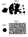
- the cylindrical container 10 has an outlet 12a through which loose carbon fibers in the form shown in Figs. 4 and 5 are introduced into the working chamber 12.
- a feed pipe 14 is connected to the cylindrical container 10.
- a feed or induction passage 16 defined within the feed pipe 14 communicates with the working chamber 12 through the inlet 12a.
- the feed passage 16 is so oriented that it enters the working chamber 12 almost at a tangent.
- the feed pipe 14 is connected to a blower 18 which serves as a pressurized gas or gaseous fluid source.
- ambient air is used as a carrier gas for the loose carbon fibers.
- any gas suitable for use as a carrier gas can be selected as a replacement for air.
- An ejector type material feeder 40 is installed at an intermediate section of the feed pipe, to which the blower 18 is connected.
- the ejector type material feeder includes an induction pipe 20 having an inlet 20a inserted into a carbon fiber reservoir (not shown), which may be in the form of hopper.
- the blower 18 generates gas flow toward the working chamber 12 through the ejector type material feeder 40 and the feed passage 16. With the gas flow, the pressure at the outlet of the induction pipe 20 inserted into the ejector type material feeder 40 becomes lower than the atmospheric pressure or vacuum to draw the carbon fiber in the reservoir via the inlet 20a.
- the carbon fiber thus drawn into the induction pipe 20 is carried by the gas flow in the feed passage 16 and introduced into the working chamber 12 through the inlet 12a.
- the above feed system which conveys the loose carbon fibers by means of an air stream is not meant to limit the invention to the shown structure and that any appropriate system can be used to feed the carbon fibers into the working chamber. Furthermore it is not essential to feed the loose carbon fibers into the working chamber with air.
- the carbon fibers may be introduced directly through an appropriate hopper into the working chamber without air flow. The air flow is introduced into the working chamber 12 after the introduction of the carbon fibers to cause circulation of the carbon firbers along the periphery of the working chamber with the introduced air flow.
- the cylindrical container 10 also has a gas outlet 24 in the center of its ceiling. Air is vented from the working chamber 12 through the gas outlet 24. A filter 26 in the gas outlet 24 prevents the carbon fibers in the working chamber from flowing out through the gas outlet.
- the cylindrical container 10 may also have a carbon fiber aggregate outlet in its floor to facilitate removal of the carbon fiber aggregate product. A closure lid may seal the carbon fiber aggregate outlet during production of carbon fiber aggregates.
- the air circulating around the working chamber 12 drives the loose carbon fibers around the circular periphery of the working chamber. As the individual carbon fibers circulate, they repeatedly separate from and recombine with the growing aggregate, each time being packed somewhat tighter with other carbon fibers.
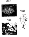
- Fig. 8 shows the structure of part of an individual carbon fiber aggregate. Since the resultant carbon fiber aggregate is in the form of a ball or nut and has a relatively high density, the resultant carbon fiber aggregates can be used in processes relying on gravity feed.
- the shape of the aggregate will vary with upon the characteristic length of the loose carbon fibers. Specifically, when relatively long carbon fibers are used, the aggregate will tend to be ellipsoidal. On the other hand, when relatively short carbon fibers are used, the aggregate will be more nearly spherical.
- a ratio ⁇ of volume (v) of the loose carbon fibers versus the volume (V) of the working chamber is an important parameter affecting formation of the carbon fiber aggregate.
- the circualting rate of the fibers and the operation time are believed to be important parameters affecting formation of the carbon fiber aggregate. For instance, in experiments, when carbon fibers with a length of 10 mm, a diameter of 16 ⁇ and a specific gravity of 1.6, and matted to a bulk specific gravity of 0.015, are processed in a cylindrical container 10 with a diameter of 30 cm, the yield of the carbon fiber aggregate is significantly lowered if the ratio ⁇ is allowed to be greater than or equal to 15%.
- the circulation rate ⁇ (rps) is set to the range of 2> ⁇ >3rps and the operation time (t) is held to less than 15 min, a cylindrical or ellipsoidal aggregate with a diameter of 2 to 3 mm is obtained.
- the individual carbon fibers making up the aggregate are essentially parallel and the density of the carbon fiber aggregate is about 0.02.
- the circulation rate is set to less than 1 rps, and operation time is set to the range of 3 to 15 min
- a cylindrical or ellipsoidal aggregate made up of parallel fibers is obtained.
- the bulk specific gravity of the aggregate is increased to 0.03.
- the aggregation operation is performed at a circulation rate in the range of 2 ⁇ 3 rps for a period longer than 15 min., the resultant aggregate will be ball-shaped and have a density of about 0.02.
- the carbon fiber aggregates obtained in the above experiment I were again circulated within the working chamber at a rate of 0.5 rps for 10 min.
- the resultant aggregates were cylindrical or ellipsoidal, 10 mm in length, 3 to 4 mm in diameter and had a density of 0.03.
- the aggregation operation was performed using the same carbon fibers as in experiment I and the operation time was expanded to 20 min.
- the resultant carbon fiber aggregates were spheres 5 to 7 mm in diameter.
- the density of the ball-shaped aggregates was 0.02.
- a cylindrical container 50 cm in diameter was used. Carbon fibers 3 mm in length, with a specific gravity of 1.6 and derived from the coal pitch was used. The bulk density of the starting carbon fiber material was 0.04. The carbon fibers were introduced into the working chamber via air stream through the feed passage. The carbon fibers were circulated at a rate of 20 rps for 30 min. The resultant carbon fiber aggregates were ball-shaped and had a bulk specific gravity of 0.15.
- the carbon fiber aggregates obtained from the foregoing experiments could be handled by gravity-feed. This makes it easy to handle carbon fiber. Furthermore, since the method and apparatus according to the present invention does not require any binder, the production cost of the aggregates can be held relatively low.
- Fig. 10 show another embodiment of a cylindrical container 10 including a cyclone.
- the cyclone has a lower, conical section 30 which collects the carbon fiber aggregates for easy removal through the bottom outlet 32. This cyclone makes collection of the finished aggregates easier.
Landscapes
- Engineering & Computer Science (AREA)
- Textile Engineering (AREA)
- Chemical & Material Sciences (AREA)
- Chemical Kinetics & Catalysis (AREA)
- Inorganic Chemistry (AREA)
- General Chemical & Material Sciences (AREA)
- Inorganic Fibers (AREA)
- Processing And Handling Of Plastics And Other Materials For Molding In General (AREA)
Applications Claiming Priority (2)
| Application Number | Priority Date | Filing Date | Title |
|---|---|---|---|
| JP60253724A JPS62114636A (ja) | 1985-11-14 | 1985-11-14 | 炭素繊維集束物の製造方法 |
| JP253724/85 | 1985-11-14 |
Publications (2)
| Publication Number | Publication Date |
|---|---|
| EP0223707A2 true EP0223707A2 (de) | 1987-05-27 |
| EP0223707A3 EP0223707A3 (de) | 1989-11-08 |
Family
ID=17255259
Family Applications (1)
| Application Number | Title | Priority Date | Filing Date |
|---|---|---|---|
| EP86402525A Withdrawn EP0223707A3 (de) | 1985-11-14 | 1986-11-13 | Kohlenstoffaseraggregat, das die Schwerkraftzuführung zulässt und Verfahren zur Herstellung desselben |
Country Status (3)
| Country | Link |
|---|---|
| EP (1) | EP0223707A3 (de) |
| JP (1) | JPS62114636A (de) |
| KR (1) | KR900001321B1 (de) |
Cited By (1)
| Publication number | Priority date | Publication date | Assignee | Title |
|---|---|---|---|---|
| US11484627B2 (en) | 2010-10-20 | 2022-11-01 | 206 Ortho, Inc. | Method and apparatus for treating bone fractures, and/or for fortifying and/or augmenting bone, including the provision and use of composite implants, and novel composite structures which may be used for medical and non-medical applications |
Family Cites Families (2)
| Publication number | Priority date | Publication date | Assignee | Title |
|---|---|---|---|---|
| US2571334A (en) * | 1946-08-30 | 1951-10-16 | Houdaille Hershey Corp | Method of making resilient batts |
| JPS5857536B2 (ja) * | 1977-03-14 | 1983-12-20 | セントラル硝子株式会社 | 繊維塊状体の製造装置 |
-
1985
- 1985-11-14 JP JP60253724A patent/JPS62114636A/ja active Pending
-
1986
- 1986-11-13 EP EP86402525A patent/EP0223707A3/de not_active Withdrawn
- 1986-11-13 KR KR1019860009586A patent/KR900001321B1/ko not_active Expired
Cited By (1)
| Publication number | Priority date | Publication date | Assignee | Title |
|---|---|---|---|---|
| US11484627B2 (en) | 2010-10-20 | 2022-11-01 | 206 Ortho, Inc. | Method and apparatus for treating bone fractures, and/or for fortifying and/or augmenting bone, including the provision and use of composite implants, and novel composite structures which may be used for medical and non-medical applications |
Also Published As
| Publication number | Publication date |
|---|---|
| JPS62114636A (ja) | 1987-05-26 |
| EP0223707A3 (de) | 1989-11-08 |
| KR870005126A (ko) | 1987-06-04 |
| KR900001321B1 (ko) | 1990-03-08 |
Similar Documents
| Publication | Publication Date | Title |
|---|---|---|
| US4770907A (en) | Method for forming metal-coated abrasive grain granules | |
| US4260265A (en) | Fiber-resin blending technique | |
| US4168913A (en) | Process for mixing particulate material | |
| WO2004076042A1 (ja) | 混合装置およびスラリー化装置 | |
| US2976574A (en) | Chemical process and product | |
| US5735403A (en) | Apparatus for removal of fine particles in material flow system | |
| US4335965A (en) | Fiber-resin blending technique | |
| US4569596A (en) | Pneumatic conveying and material blending apparatus and method | |
| JPH0318997B2 (de) | ||
| EP0223707A2 (de) | Kohlenstoffaseraggregat, das die Schwerkraftzuführung zulässt und Verfahren zur Herstellung desselben | |
| CN113546728A (zh) | 一种碳化硅微粉研磨系统及其使用方法 | |
| EP0528257B1 (de) | Pulververarbeitungsverfahren | |
| US4134553A (en) | Grinding apparatus | |
| CN208247319U (zh) | 一种用于导光板加工的注塑机料斗 | |
| CN212493975U (zh) | 一种碳化硅微粉分级设备 | |
| CN1053592A (zh) | 用于颗粒材料的送料器 | |
| CN210286767U (zh) | 一种生产碳化硼用的制备装置 | |
| CN101844044A (zh) | 粉料连续均化分级系统 | |
| CN217110210U (zh) | 碳纤维粉生产加工用高效率冷却降温设备 | |
| KR102915546B1 (ko) | 소결광의 제조 방법 및 소결광 | |
| CA1090970A (en) | Compaction of pulverised rubber mixtures | |
| CN116789086B (zh) | 一种氮化硅粉体的生产工艺 | |
| CN223988839U (zh) | 一种造粒机烟尘处理设备 | |
| CN220609907U (zh) | 一种高碳石墨快速混料装置 | |
| GB2156699A (en) | Pneumatic conveying and material blending apparatus and method |
Legal Events
| Date | Code | Title | Description |
|---|---|---|---|
| PUAI | Public reference made under article 153(3) epc to a published international application that has entered the european phase |
Free format text: ORIGINAL CODE: 0009012 |
|
| AK | Designated contracting states |
Kind code of ref document: A2 Designated state(s): DE FR GB NL |
|
| PUAL | Search report despatched |
Free format text: ORIGINAL CODE: 0009013 |
|
| AK | Designated contracting states |
Kind code of ref document: A3 Designated state(s): DE FR GB NL |
|
| STAA | Information on the status of an ep patent application or granted ep patent |
Free format text: STATUS: THE APPLICATION IS DEEMED TO BE WITHDRAWN |
|
| 18D | Application deemed to be withdrawn |
Effective date: 19900509 |
|
| RIN1 | Information on inventor provided before grant (corrected) |
Inventor name: MARUI, TOMOHIROC/O KAWASAKI STEEL CORP. Inventor name: AO, KAZUOC/O KAWASAKI STEEL CORP. Inventor name: KANEKO, TADAOC/O KAWASAKI STEEL CORP. |