EP0223749B1 - Axialfluss-Dresch- und -Trennvorrichtungseinheit für Mähdrescher - Google Patents
Axialfluss-Dresch- und -Trennvorrichtungseinheit für Mähdrescher Download PDFInfo
- Publication number
- EP0223749B1 EP0223749B1 EP86830336A EP86830336A EP0223749B1 EP 0223749 B1 EP0223749 B1 EP 0223749B1 EP 86830336 A EP86830336 A EP 86830336A EP 86830336 A EP86830336 A EP 86830336A EP 0223749 B1 EP0223749 B1 EP 0223749B1
- Authority
- EP
- European Patent Office
- Prior art keywords
- thresher
- separator
- chain
- chains
- gears
- Prior art date
- Legal status (The legal status is an assumption and is not a legal conclusion. Google has not performed a legal analysis and makes no representation as to the accuracy of the status listed.)
- Expired
Links
- 241001124569 Lycaenidae Species 0.000 title description 4
- 238000004140 cleaning Methods 0.000 claims description 8
- 239000000463 material Substances 0.000 description 4
- 241000251169 Alopias vulpinus Species 0.000 description 2
- 230000005540 biological transmission Effects 0.000 description 2
- 239000002184 metal Substances 0.000 description 1
Images


Classifications
-
- A—HUMAN NECESSITIES
- A01—AGRICULTURE; FORESTRY; ANIMAL HUSBANDRY; HUNTING; TRAPPING; FISHING
- A01F—PROCESSING OF HARVESTED PRODUCE; HAY OR STRAW PRESSES; DEVICES FOR STORING AGRICULTURAL OR HORTICULTURAL PRODUCE
- A01F7/00—Threshing apparatus
- A01F7/02—Threshing apparatus with rotating tools
- A01F7/06—Threshing apparatus with rotating tools with axles in line with the feeding direction ; Axial threshing machines
- A01F7/065—Threshing apparatus with rotating tools with axles in line with the feeding direction ; Axial threshing machines with cage sweep mechanisms
Definitions
- the present invention relates to combine harvesters having an axial-flow thresher-separator unit.
- the invention relates to an axial-flow thresher-separator unit for combine harvesters, of the type comprising:
- a thresher unit of the type described above is the subject of European Patent No. 0 070 260 corresponding to the Italian Patent Application No. 67 968-A/81, both by the same Applicants.
- the elongate members for cleaning the outer surface of the separator casing are connected at their ends to endless chains which are located on the outer surface of the separator casing along portions of circular arcs lying in a plane perpendicular to the axis of the thresher-separator cylinder so that each chain has an inner portion facing the surface of the separator casing and an outer portion.
- the chains are always driven in the same direction.
- the elongate cleaning members move along the portion adjacent to the separator casing in one direction and along the outer portion in the opposite direction. Even though the outer portion is further from the surface of the casing than the inner portion, the cleaning action of the elongate members occurs when the elongate member moves over both these said portions.
- the object of the present invention is to provide a thresher-separator unit which does not have these disadvantages.
- a thresher-separator unit of the type described above characterised in that the means for rotating the shaft are arranged to transmit an alternating rotary movement to the gears, in that each of the chains is an open loop and is guided within a double rail constituted by two parallel strips located above and beneath the pins of the chain, and in that the longitudinal edges of each strip slidably engage the facing surface of the two plates constituting each inner link of the chain.
- thresher-separator unit can also be applied to combine harvesters of a type different from that illustrated.
- the combine harvester includes wheels 2 (only the front ones of which are visible in the drawing) on which is mounted a fixed structure 3.
- the combine harvester 1 is provided at its front end with a cutting platform 4 including a feed screw 5 of known type.
- a thresher-separator unit 6 of the axial-flow type which is illustrated in perspective in Figure 2.
- the thresher-separator unit 6 includes a thresher-separator cylinder located transverse the longitudinal axis of the machine.
- a counter-thresher 8 constituted by a concave surrounds the lower portion of the thresher-separator cylinder 7, and a separator casing 9 constituted by a perforated tubular body surrounds the part of the cylinder 7 which is not covered by the counter-thresher 8.
- the separator casing 9 has an aperture 11 (see Figure 1) at one end, through which the harvested crop is intended to be supplied to the space between the cylinder 1 and the casing 9.
- the thresher-separator unit 6 includes a fixed support structure 16 (see Figure 2) forming a mouth 11 a for conveying the crop in correspondence with the aperture 11 in the separator casing 9.
- a transverse feed roller 10 is disposed in the opening 11 a for receiving the product from the screw 5 and conveying it to the unit 6.
- the crop supplied to the interior of the separator casing 9 follows a helical path around the thresher-separator cylinder 7 and moves towards the opposite end of the cylinder. When it reaches this end, the material which has not passed through the apertures in the separator casing is discharged directly to the ground so as to form a line to one side of the harvester. The remaining material separated during the movement of the crop around the thresher cylinder, however, falls below the separator casing 9 and is deposited on a collecting base 12 (see Figure 1) located beneath the thresher-separator unit 6.
- the harvester has a screw 13 which is located in correspondence with the collecting base 12 and conveys the grain towards the loading end of a blade elevator 14 which conveys the grain, through a second elevator 15, to the cleaning members (not illustrated) located in the rear part of the harvester.
- These members are of known type and do not fall within the scope of the present invention.
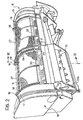
- Figure 2 is a perspective view ofthethresher-separator unit 6 without the thresher-cylinder 7.
- the fixed support structure 16 of the unit 6 includes three ribs 17 located at the ends and in the central zone of the separator casing 9, respectively.
- each chain 19 engaged with one of the gears 18 is guided within a double rail 20 constituted by two parallel strips 20a, 20b located above and below the pins 21 of the chain 19.
- the longitudinal edges of each strip 20a, 20b slideably engage the facing surface of the two plates 22 constituting each inner link of the chain 19.
- the double rail 20 is fixed to the ribs 17 by support members 23.
- the double rail is interrupted in the zone of meshing between the gear 18 and the chain 19.
- This zone is shown in perspective in Figure 4, on an enlarged scale, while Figure 5 is a section taken on the line V-V of Figure 4.
- the chain 19 is supported by two upper vertical plates 24 and two lower vertical plates 25, the longitudinal facing edges of which slidably engage the corresponding longitudinal edges of the plates 22 constituting the inner links of the chain.
- the two portions of the upper strip 20a facing the zone of meshing between the gear and the chain are bent so as to form an eyelet within which is inserted a bolt 26 constituting the element for fixing the vertical plates 24 to the two portions of strip 20a.
- the two lower plates 25 are similarly connected to the two portions of strips 20b.
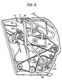
- the two gears 18 are rotatably interconnected by a shaft 27 which is driven to effect an alternating rotary movement by means of a crank and connecting rod transmission 28 illustrated in detail in Figure 6.
- This transmission includes a rotary disc 29 pivoted on the fixed structure, a toothed sector 30 also pivoted on the fixed structure, and a connecting rod 31 pivoted at one end 31 a to a point on the periphery of the disc 29 and at its other end 31 b to a point on the toothed sector spaced from its point of pivoting to the fixed structure.
- the toothed sector engages a sprocket 32 which is fixed to the shaft 27 carrying the gears 18.
- the four chains 19 support, in pairs, a pair of rods 33 which are intended to act as cleaning members to prevent any separated material accumulating in the upper part of the separator casing 9.
- Each rod 33 is fixed at its two ends to the corresponding chains 19.
- the chains 19 are driven so as to cause the rods 33 to reciprocate on a cylindrical sector adjacent the upper part of the outer surface of the separator casing 9, thus removing any material which tends to accumulate in this zone.
Landscapes
- Life Sciences & Earth Sciences (AREA)
- Environmental Sciences (AREA)
- Threshing Machine Elements (AREA)
Claims (3)
dadurch gekennzeichnet, daß die Einrichtung (28) zum Drehen der Welle (27) dafür vorgesehen ist, eine wechselnde Drehbewegung auf die Zahnräder (18) zu übertragen, daß jede der Ketten (19) eine offene Schleife ist und in einer doppelten Schiene (20) geführt wird, die gebildet wird durch zwei parallele Streifen (20a, 20b), welche oberhalb und unterhalb der Stifte (21) der Kette (19) angeordnet sind, und daß die Längskanten jedes Streifens (20a, 20b) in Gleitkontakt stehen mit den ihnen gegenüberliegenden Flächen der zwei Platten (22), die jedes innere Glied der Kette (19) bilden.
Applications Claiming Priority (2)
| Application Number | Priority Date | Filing Date | Title |
|---|---|---|---|
| IT5406185U | 1985-11-19 | ||
| IT8554061U IT206721Z2 (it) | 1985-11-19 | 1985-11-19 | Perfezionamenti al gruppo battitore separatore a flusso assiale per macchine mietitrebbiatrici |
Publications (2)
| Publication Number | Publication Date |
|---|---|
| EP0223749A1 EP0223749A1 (de) | 1987-05-27 |
| EP0223749B1 true EP0223749B1 (de) | 1989-12-20 |
Family
ID=11286547
Family Applications (1)
| Application Number | Title | Priority Date | Filing Date |
|---|---|---|---|
| EP86830336A Expired EP0223749B1 (de) | 1985-11-19 | 1986-11-10 | Axialfluss-Dresch- und -Trennvorrichtungseinheit für Mähdrescher |
Country Status (5)
| Country | Link |
|---|---|
| US (1) | US4718434A (de) |
| EP (1) | EP0223749B1 (de) |
| DE (1) | DE3667588D1 (de) |
| ES (1) | ES2012358B3 (de) |
| IT (1) | IT206721Z2 (de) |
Families Citing this family (4)
| Publication number | Priority date | Publication date | Assignee | Title |
|---|---|---|---|---|
| US7059961B2 (en) * | 2004-01-12 | 2006-06-13 | Cnh America Llc | Apparatus and method for effecting movement and clearance spacing of a concave |
| US9179603B2 (en) * | 2012-12-20 | 2015-11-10 | Agco Corporation | Combine cleaning system without a shaking sieve |
| US11832557B2 (en) * | 2018-04-11 | 2023-12-05 | Cnh Industrial America Llc | Rotational rotor discharge deflector |
| GB201810243D0 (en) * | 2018-06-22 | 2018-08-08 | Agco Corp | Concave change system |
Family Cites Families (8)
| Publication number | Priority date | Publication date | Assignee | Title |
|---|---|---|---|---|
| US4108150A (en) * | 1977-03-23 | 1978-08-22 | Allis-Chalmers Corporation | Agitator for an axial flow cylinder |
| US4180081A (en) * | 1977-06-23 | 1979-12-25 | Allis-Chalmers Corporation | Distribution augers for an axial flow combine |
| US4154250A (en) * | 1978-03-03 | 1979-05-15 | Allis-Chalmers Corporation | Drive mechanism and support arrangement for agitator of axial flow threshing cylinder |
| US4222395A (en) * | 1979-04-30 | 1980-09-16 | Allis-Chalmers Corporation | Threshing cage fingers for retarding the flow of material through an axial flow harvester |
| US4337781A (en) * | 1980-03-31 | 1982-07-06 | Allis-Chalmers Corporation | Roller support for cage sweep mechanism |
| US4274426A (en) * | 1980-03-31 | 1981-06-23 | Williams Dennis W | Threshing apparatus |
| IT1144300B (it) * | 1981-07-13 | 1986-10-29 | Laverda Spa Pietro | Gruppo battitore separatore a flusso assiale per macchine mietitrebbiatrici |
| DE3363911D1 (en) * | 1982-06-19 | 1986-07-10 | Sperry Nv | Combine harvesters |
-
1985
- 1985-11-19 IT IT8554061U patent/IT206721Z2/it active
-
1986
- 1986-11-10 ES ES86830336T patent/ES2012358B3/es not_active Expired - Lifetime
- 1986-11-10 DE DE8686830336T patent/DE3667588D1/de not_active Expired - Lifetime
- 1986-11-10 EP EP86830336A patent/EP0223749B1/de not_active Expired
- 1986-11-19 US US06/932,414 patent/US4718434A/en not_active Expired - Fee Related
Also Published As
| Publication number | Publication date |
|---|---|
| US4718434A (en) | 1988-01-12 |
| IT206721Z2 (it) | 1987-10-01 |
| ES2012358B3 (es) | 1990-03-16 |
| EP0223749A1 (de) | 1987-05-27 |
| IT8554061V0 (it) | 1985-11-19 |
| DE3667588D1 (de) | 1990-01-25 |
Similar Documents
| Publication | Publication Date | Title |
|---|---|---|
| US9775294B2 (en) | Modular gathering platform for grain harvesters | |
| DE60201993T2 (de) | Abschirmmittel für einen elevator einer landwirtschaftlichen erntemaschine | |
| US4236369A (en) | Row crop attachment | |
| EP3219195B1 (de) | Landwirtschaftliche zuführeranordnung mit einem abgeschirmten kettenrad | |
| EP1769669B1 (de) | Stab für einen Kettenförderer | |
| BR102019008401B1 (pt) | Espigadeira de cultivo em fileira e divisor de cultivo para uma máquina agrícola, e, combinada | |
| EP3501259B1 (de) | Rücklaufschale für einen landwirtschaftlichen mähdrescher | |
| US4177626A (en) | Crop gathering apparatus | |
| US4083167A (en) | Multi-row crop header | |
| US4266394A (en) | Gathering means mounting assembly for row crop harvesters | |
| US4718434A (en) | Axial-flow thresher-separator units for combine harvesters | |
| US4271660A (en) | Combine conveyor apparatus | |
| US3913303A (en) | Feed roll construction for forage harvester | |
| CA2224140A1 (en) | Row crop header with multiple row conveying system | |
| US2849103A (en) | Auger conveyor | |
| DE2248445A1 (de) | Plattenbandfoerderer fuer maehdrescher oder dergleichen | |
| US4003191A (en) | Barrier means in a combine harvesting header | |
| US4337612A (en) | Row crop unit | |
| US4397134A (en) | Row crop attachment with sweeper chain | |
| CA1176534A (en) | Self-propelling harvester-thresher | |
| EP0070260B1 (de) | Axialfluss-Dresch- und Trennvorrichtungseinheit für Mähdrescher | |
| JP2008072919A (ja) | コンバイン | |
| EP0554510A1 (de) | Tabakerntemaschine | |
| EP0098336B1 (de) | Erntemaschine für in Reihe stehende Halmfrüchte | |
| SU1121799A1 (ru) | Транспортерный подборщик к уборочной сельскохоз йственной машине |
Legal Events
| Date | Code | Title | Description |
|---|---|---|---|
| PUAI | Public reference made under article 153(3) epc to a published international application that has entered the european phase |
Free format text: ORIGINAL CODE: 0009012 |
|
| AK | Designated contracting states |
Kind code of ref document: A1 Designated state(s): DE ES FR GB IT |
|
| 17P | Request for examination filed |
Effective date: 19870516 |
|
| RAP1 | Party data changed (applicant data changed or rights of an application transferred) |
Owner name: FIATGEOTECH - TECNOLOGIE PER LA TERRA S.P.A. |
|
| 17Q | First examination report despatched |
Effective date: 19890206 |
|
| GRAA | (expected) grant |
Free format text: ORIGINAL CODE: 0009210 |
|
| AK | Designated contracting states |
Kind code of ref document: B1 Designated state(s): DE ES FR GB IT |
|
| ITF | It: translation for a ep patent filed | ||
| REF | Corresponds to: |
Ref document number: 3667588 Country of ref document: DE Date of ref document: 19900125 |
|
| ET | Fr: translation filed | ||
| PLBE | No opposition filed within time limit |
Free format text: ORIGINAL CODE: 0009261 |
|
| STAA | Information on the status of an ep patent application or granted ep patent |
Free format text: STATUS: NO OPPOSITION FILED WITHIN TIME LIMIT |
|
| 26N | No opposition filed | ||
| PGFP | Annual fee paid to national office [announced via postgrant information from national office to epo] |
Ref country code: GB Payment date: 19911015 Year of fee payment: 6 |
|
| PGFP | Annual fee paid to national office [announced via postgrant information from national office to epo] |
Ref country code: DE Payment date: 19911021 Year of fee payment: 6 |
|
| PGFP | Annual fee paid to national office [announced via postgrant information from national office to epo] |
Ref country code: ES Payment date: 19911107 Year of fee payment: 6 |
|
| PGFP | Annual fee paid to national office [announced via postgrant information from national office to epo] |
Ref country code: FR Payment date: 19911129 Year of fee payment: 6 |
|
| ITTA | It: last paid annual fee | ||
| PG25 | Lapsed in a contracting state [announced via postgrant information from national office to epo] |
Ref country code: GB Effective date: 19921110 |
|
| PG25 | Lapsed in a contracting state [announced via postgrant information from national office to epo] |
Ref country code: ES Free format text: LAPSE BECAUSE OF NON-PAYMENT OF DUE FEES Effective date: 19921111 |
|
| GBPC | Gb: european patent ceased through non-payment of renewal fee |
Effective date: 19921110 |
|
| PG25 | Lapsed in a contracting state [announced via postgrant information from national office to epo] |
Ref country code: FR Effective date: 19930730 |
|
| PG25 | Lapsed in a contracting state [announced via postgrant information from national office to epo] |
Ref country code: DE Effective date: 19930803 |
|
| REG | Reference to a national code |
Ref country code: FR Ref legal event code: ST |
|
| REG | Reference to a national code |
Ref country code: ES Ref legal event code: FD2A Effective date: 19931214 |
|
| PG25 | Lapsed in a contracting state [announced via postgrant information from national office to epo] |
Ref country code: IT Free format text: LAPSE BECAUSE OF NON-PAYMENT OF DUE FEES;WARNING: LAPSES OF ITALIAN PATENTS WITH EFFECTIVE DATE BEFORE 2007 MAY HAVE OCCURRED AT ANY TIME BEFORE 2007. THE CORRECT EFFECTIVE DATE MAY BE DIFFERENT FROM THE ONE RECORDED. Effective date: 20051110 |