EP0223760B1 - Seal for a box enclosing a compact disc or tape cassette - Google Patents
Seal for a box enclosing a compact disc or tape cassette Download PDFInfo
- Publication number
- EP0223760B1 EP0223760B1 EP86850387A EP86850387A EP0223760B1 EP 0223760 B1 EP0223760 B1 EP 0223760B1 EP 86850387 A EP86850387 A EP 86850387A EP 86850387 A EP86850387 A EP 86850387A EP 0223760 B1 EP0223760 B1 EP 0223760B1
- Authority
- EP
- European Patent Office
- Prior art keywords
- box
- seal
- latch
- blocking
- aperture
- Prior art date
- Legal status (The legal status is an assumption and is not a legal conclusion. Google has not performed a legal analysis and makes no representation as to the accuracy of the status listed.)
- Expired
Links
- 230000000903 blocking effect Effects 0.000 claims description 53
- 125000006850 spacer group Chemical group 0.000 claims description 3
- 238000006073 displacement reaction Methods 0.000 claims description 2
- 239000000463 material Substances 0.000 description 8
- 239000004033 plastic Substances 0.000 description 4
- 229920003023 plastic Polymers 0.000 description 4
- 229920000298 Cellophane Polymers 0.000 description 2
- 229910000831 Steel Inorganic materials 0.000 description 2
- 230000003213 activating effect Effects 0.000 description 2
- 238000005304 joining Methods 0.000 description 2
- 239000002985 plastic film Substances 0.000 description 2
- 229920006255 plastic film Polymers 0.000 description 2
- -1 polyethylene Polymers 0.000 description 2
- 239000010959 steel Substances 0.000 description 2
- 239000004698 Polyethylene Substances 0.000 description 1
- 239000004743 Polypropylene Substances 0.000 description 1
- 238000005336 cracking Methods 0.000 description 1
- 238000005034 decoration Methods 0.000 description 1
- 230000001419 dependent effect Effects 0.000 description 1
- 230000000881 depressing effect Effects 0.000 description 1
- 230000000994 depressogenic effect Effects 0.000 description 1
- 230000014759 maintenance of location Effects 0.000 description 1
- 238000004519 manufacturing process Methods 0.000 description 1
- 239000002184 metal Substances 0.000 description 1
- 238000000034 method Methods 0.000 description 1
- 238000000465 moulding Methods 0.000 description 1
- 229920000515 polycarbonate Polymers 0.000 description 1
- 239000004417 polycarbonate Substances 0.000 description 1
- 229920000573 polyethylene Polymers 0.000 description 1
- 229920001155 polypropylene Polymers 0.000 description 1
- 238000003825 pressing Methods 0.000 description 1
- 230000000717 retained effect Effects 0.000 description 1
- 238000007789 sealing Methods 0.000 description 1
Images




Classifications
-
- G—PHYSICS
- G11—INFORMATION STORAGE
- G11B—INFORMATION STORAGE BASED ON RELATIVE MOVEMENT BETWEEN RECORD CARRIER AND TRANSDUCER
- G11B33/00—Constructional parts, details or accessories not provided for in the other groups of this subclass
- G11B33/02—Cabinets; Cases; Stands; Disposition of apparatus therein or thereon
- G11B33/04—Cabinets; Cases; Stands; Disposition of apparatus therein or thereon modified to store record carriers
- G11B33/0405—Cabinets; Cases; Stands; Disposition of apparatus therein or thereon modified to store record carriers for storing discs
- G11B33/0411—Single disc boxes
- G11B33/0416—Single disc boxes for disc cartridges
-
- B—PERFORMING OPERATIONS; TRANSPORTING
- B65—CONVEYING; PACKING; STORING; HANDLING THIN OR FILAMENTARY MATERIAL
- B65D—CONTAINERS FOR STORAGE OR TRANSPORT OF ARTICLES OR MATERIALS, e.g. BAGS, BARRELS, BOTTLES, BOXES, CANS, CARTONS, CRATES, DRUMS, JARS, TANKS, HOPPERS, FORWARDING CONTAINERS; ACCESSORIES, CLOSURES, OR FITTINGS THEREFOR; PACKAGING ELEMENTS; PACKAGES
- B65D55/00—Accessories for container closures not otherwise provided for
- B65D55/02—Locking devices; Means for discouraging or indicating unauthorised opening or removal of closure
- B65D55/06—Deformable or tearable wires, strings or strips; Use of seals
-
- E—FIXED CONSTRUCTIONS
- E05—LOCKS; KEYS; WINDOW OR DOOR FITTINGS; SAFES
- E05B—LOCKS; ACCESSORIES THEREFOR; HANDCUFFS
- E05B73/00—Devices for locking portable objects against unauthorised removal; Miscellaneous locking devices
- E05B73/0017—Anti-theft devices, e.g. tags or monitors, fixed to articles, e.g. clothes, and to be removed at the check-out of shops
- E05B73/0023—Containers, boxes, cases or the like, e.g. for compact discs or video-cassettes, specially adapted therefor
Definitions
- the invention relates to a seal. of a box enclosing a compact disc or tape cassette, including e.g. MC, Video, and DAT cassettes, comprising two rectangular box halves which are hingedly connected to each other.
- a seal. of a box enclosing a compact disc or tape cassette including e.g. MC, Video, and DAT cassettes, comprising two rectangular box halves which are hingedly connected to each other.
- the seal of the invention comprises a blocking element being applied to the box on the outside thereof so as to engage the two box halves when the box is in the closed position.
- DE-U-8 422 027 discloses a seal of a box enclosing a compact disc or tape cassette comprising two rectangular box halves which are hingedly connected to each other.
- the seal comprises a blocking element to be applied to the box on the outside thereof so as to engage the two box halves when the box is in the closed position.
- the blocking element can easily be provided with a marking activating a protecting system, in such a manner that the marking cannot be removed e.g. by moulding or otherwise including the marking into the material of which the blocking element is made, or by applying the marking to a side surface of the blocking element, facing the box, so that it is not available when the blocking element is applied to the cassette.
- the blocking element is well suited for multiple use, because it can be removed from the box by means of the special tool when payment is being effected, without the blocking element being broken or destroyed in other respects.
- the box shown in Figs. 1 to 3 in the drawings is of the type commonly known for enclosing compact discs.
- the box comprises two halves 10 and 11 which are hingedly interconnected for pivotal movement about an axis 12.
- One box half 10 is tailored to receive therein the compact disc while the other box half 11 forms a cover on the box half 10.
- the box in its entirety is made of a plastic material and at least the box half 11 is transparent such that a decoration and/or an information text on the disc in the box can be exposed by locating a printed insert of paper or plastic material inside the box.
- the box half 11 can have two pairs of opposite flaps on edge flanges on the cover, each of these flaps being combined with an edge aperture 13 for manufacturing reasons.
- the seal of the invention comprises a U-shaped blocking bow of some transparent or semi-transparent rather durable plastic material having some elasticity and springiness in order that the bow can be deformed to some extent without cracking.
- a suitable plastic material is chosen from the group comprising polycarbonate, polyethylene, and polypropylene. However, also steel or other metal can be used for the bow.
- the bow comprises a flat web 14 and two limbs 15 and 16 extending perpendicularly to the web.
- One limb 15 has a flap 17 projecting perpendicularly inwardly therefrom, and the other limb 16 forms two sockets 18 having hooks 19 facing away from each other.
- the bow is applied to the closed box by the web 14 of the bow being positioned against the outside surface of the box half 10 while the flap 17 on one limb of the bow is inserted into one of the two opposite edge apertures 13 or an edge aperture in the box half 11 provided specifically for this purpose.
- the sockets 18 provided on the other limb are inserted in the opposite edge aperture 13 or an edge aperture provided specifically for this purpose, in order that the hooks 19 of the sockets shall engage by snap action the edges of this aperture, the bow material allowing the sockets to be resiliently moved towards each other.
- the blocking bow keeps the two box halves together and prevents opening of the box without further. This cannot be done without breaking the frame if a special tool is not available for removing the blocking bow.
- the blocking bow can be removed by the cashier by using such special tool by means of which the sockets 18 are pressed towards each other in order to disengage the hooks 19 from the edges of the aperture 13.
- a tool of this type can comprise pins which are inserted into the sockets and are actuated to angle the pins so as to move the ends thereof forming the hooks towards each other.
- the blocking bow can be provided with a marking for activating a protecting system.
- marking either can be embedded into the frame material or can be applied to the side surface of the bow web which in the operative position of the bow is facing the box so that the marking is not available for damage.
- the blocking element is made as a bow in the manner described above, because it can also comprise a closed frame which extends around the box along the edges thereof, the frame at least to some extent being of U-shaped cross-sectional form to embrace the two box halves.
- the frame can be opened but is kept together in the operative position thereof by means of the latch mechanism which can be actuated by means of said special tool.
- FIG. 4 to 8 An alternative to the latch mechanism including the sockets 18 with the hooks 19 is shown in Figs. 4 to 8.
- This latch mechanism includes a U-shaped male element 20 of a material allowing the limbs of the member to be pressed against each other.
- Each limb has two projections 21 on the outer edge thereof and forms a shoulder 22 on the inner edge thereof.
- a through aperture 23 having recesses 24'for receiving therein the projections 21 when the male element is inserted into the aperture.
- Two side openings 25 in register with each other extend from the outside up to the aperture 23.
- the blocking bow is locked by the male latch element 20 being pushed into the aperture 23 so that the projections 21 can engage by snap action into the recesses 24, the element projecting into the edge aperture 13 in the box half 10 as is shown in Fig. 5. Then, the blocking bow is locked. It can be unlocked by inserting two pins 26 into the openings 25 and by pressing these pins against the limbs of the element 20 so that the projections 21 are disengaged from the recesses 24 while a key 27 is inserted into the latch male element in order to engage the shoulders 22 at a head 28 on the key when the limbs of the latch male element are resiliently pressed together.
- the latch male element arrives at the position according to Fig.
- the two lower projections on this element will engage by snap action the two upper recesses in the aperture 23 so that the latch male element will disengage from the key and now will be retained in an unlocked position in which it allows the blocking bow to be removed from the box.
- the latch male element is pressed into the aperture 23 to the position shown in Fig. 5.
- the latch male element is not at all available for unlocking same without using a special tool which comprises the pins 26 and the key 27 for cooperation with the latch male element in the manner described above.
- each a projection 28 The edge surfaces of the'limbs of the latch male element form each a projection 28. These projections are laterally displaced in relation to each other so that they can overlap when the limbs of the element are pressed together and they form guide members which stabilize the latch male element when the limbs thereof are resiliently pressed together.
- the latch male element 20 can be reinforced by a steel strip 29 extending along the lower side of the web and partly along the outside edges of the limbs. It is hooked into the element at 30.
- Fig. 9 discloses some improvements that can be made on the latch male element 20.
- a transverse sharp edge 31 is provided the purpose of which is to cut through a wrapping of plastic film or cellophane enclosing the box, when the latch male element is pushed into the aperture 23 to the operative locking position.
- a bolt 32 forming a spacer between inside projections 28 on the limbs of the element 20 which in this case are in register.
- the bolt is maintained in this position by a spring element 33.
- the two limbs are positively maintained in the position in which the projections 21 engage the recesses 24 when the latch male element is in the operative position:
- the bolt 32 can be displaced from the position between the projections 28 by the key 27 when moved into the element 20 to engage the shoulders 22.
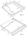
- said element forms a frame the end walls 15 and 16 of which extend along two opposite edge surfaces of the box 10 when the blocking frame is applied to the box.
- Two webs 34 and 35 extend between the end walls 15 and 16 at one end portion thereof to be located on opposite flat sides of the box.
- the web 14 is integral with a side wall 36 which extends between the end walls 15 and 16 and joins these end walls at the other end thereof so as to cover one of the edge surfaces of the other pair of opposite edge surfaces of the box when the blocking frame is applied to the box.
- a stiffening triangular corner web 37 is provided between the side wall 36 and the end wall 15 in parallel with the web 14.
- the web 14 forms a widened portion where a coil forming part of a protecting system may be mounted.
- This web may be shaped in many other ways.
- the end wall 16 forms a thickened portion 38 in which the aperture 23 for the latch male element 20 is provided.
- the apparatus shown in Figs. 14 to 18 is constructed for unlocking a latch mechanism of the type described with reference to Figs. 4 to 6 by applying the functional principles disclosed in said figures.
- a vertical bracket 40 is mounted to a base plate 41 and a channelled rail 42 is pivotally mounted at one end to the bracket at the upper end thereof by means of a pin 43.
- the rail is dimensioned to receive therein a box for a compact disc with a blocking frame as shown in Figs. 10 to 13 applied to the box and forms a bottom recess 44 to receive therein the portion 38 of the blocking frame when the end wall 16 is engaged with the bottom of the channelled rail 42.
- a lever 45 also pivotally mounted on the pin 43 for movement about the same axis as the rail 42 but independently thereof is provided at the free end thereof with the key 27, and an opening 46 is formed in the bottom of the rail 42 to receive the key when the lever 45 is engaged with the lower side of the bottom of the rail at the free end of the lever under the bias of a helical spring 48 engaged between the rail and the lever.
- Two rollers 49 and 50 are rotatably mounted in a support element 51 which is pivotally mounted to the bracket 40 by means of a pin 52 extending in parallel to the pin 43.
- the roller 49 is engagable with the top surface of the lever 45 and rests normally on said surface under the weight of the support element 51 and the rollers mounted thereon as shown in Fig. 14, and the roller 50 is engagable with the lower surface of the bottom of the rail 42.
- a block 53 is displaceably guided on two pins 54 projecting perpendicularly from one side of the rail 42 for displacement along said pins and mounts two pegs 55 projecting in parallel in spaced relationship from the side surface of the block 53 facing the rail. These pegs are received in an opening 56 in the adjacent side wall of the rail and are bevelled at 57 on the edge surfaces facing each other at the free ends of the pegs.
- a guide roller 58 is rotatably mounted to the block 53 in a cut-out 59 formed by the block and is received in a slot 60 formed by a guide element 61 mounted to the base plate 41 and projecting upwards therefrom.
- This guide element forms an abutment 62 and the rail 42 is biased by means of a helical spring 63 in the clockwise direction about the pin 43 so as to keep normally the rail in the position shown in Fig. 14, the block engaging the abutment 62 in this position of the rail.
- the slot 60 in the guide element 61 forms an inclined portion 60A and a vertical portion 60B in order to impart to the block by the intermediary of the roller 58 a movement along the pins 54 when the rail is swung in the counter-clockwise direction against the spring bias 63.
- the block is moved initially during such swinging movement of the rail from the position shown in Fig. 15 to the position shown in Fig. 18 when the roller 58 passes through the slot portion 60A and will be maintained in the position of Fig. 18 when the roller 58 continues through the slot portion 60B.
- the rail 42 is shown therein by solid lines in an initial pivoted position in which the block 53 has been displaced by the intermediary of the guide mechanism 58, 60 from the position in Fig. 15 to the position in Fig. 18 so as to engage the limbs of the latch male element with the cross head of the key 27 at the shoulders 22 as previously described with reference to Fig. 5, the key projecting into the latch male element when received by the opening 46 as shown in Fig. 17.
- the pivotal movement of the rail 42 from the position in Fig. 14 to the position in Fig. 17 is obtained by depressing the rail against the bias of the spring 63 when the box with the blocking frame applied to it is engaged with and is pressed against the bottom of the rail, the portion 38 being received by the recess 44 as mentioned above.
- the roller 50 will be engaged with the lower surface of the bottom of the rail 42 and will impart to the lever 45 a pivotal movement about the pin 43 in the counter-clockwise direction against the bias of the spring 48 in relation to the rail 42 so that the key 27 will be partly withdrawn from the opening 46 as shown by dot and dash lines in Fig. 17.
- the key 27 engaged with the latch male element 20 will pull said element to the unlocked position as described with reference to Figs. 5 and 6.
- the latch male element will be in the position shown in Fig. 6 and the blocking frame can again be removed from the box.
- the apparatus will return to the normal position shown in Fig. 14 under the bias of the springs 48 and 63 when the pressure against the rail is relieved and the box is removed from the rail.
- FIG. 19 disclose a blocking frame for a cassette tape box.
- the frame forms end walls 15 and 16, a thickened portion 38 being formed by the end wai) 16 for receiving the latch mechanism, and side walls 36A and 36B.
- the frame has a web 14 joining the end walls and the side walls so that the frame in fact forms a tray wherein the web 14 is the bottom and the walls 15, 16, 36A, and 36B are the side walls.
- Triangular web portions 70 are formed integrally with the wall 15 and the joining walls 36A and 36B at the corners formed between said walls and these webs are slightly angled outwards as will be seen in Figs. 20 and 21.
- a cassette tape box can be positioned in the frame by inserting the lower end thereof inside the webs and then moving the box into the frame so that it is totally enclosed by the frame.
- the latch male element 20 is then inserted into the portion 38 in the manner previously described so as to be located on the outside surface of the box as is indicated in Fig. 20, the box thus being locked in the blocking frame.
- the latch male element 20' forms a shoulder 74 defining the locking position of the element by engaging the box fragmentarily indicated at 78 in Fig. 24.
- the latch male element 20' shown therein is shaped substantially as previously described with projections 21.
- the element also forms two hook portions 71 and 72 for engagement with an aperture 73 and a shoulder 74, respectively, formed by the portion 38 of the blocking frame, when the latch male element is in the locked position.
- These hook portions are not available from the outside and provide increased safety against unauthorized unlocking of the blocking frame.
- the hook portion 71 can be disengaged from the aperture 73 by means of a pin 75 which is moved through the aperture 73 e.g.
- the hook portion 72 can be disengaged by means of a wedge 76 which is pressed against said hook portion e.g. by the engagement of the box with the rail 42 in the apparatus of Figs. 14 to 18. Since the latch member is available on the outside of the box it can be pushed to the disengaged position when the limbs have been pressed together and the hooks have been disengaged. Accordingly, it is not necessary to use a key 27 in this case.
Landscapes
- Engineering & Computer Science (AREA)
- Mechanical Engineering (AREA)
- Multimedia (AREA)
- Packaging Of Annular Or Rod-Shaped Articles, Wearing Apparel, Cassettes, Or The Like (AREA)
- Packaging For Recording Disks (AREA)
- Closures For Containers (AREA)
Priority Applications (4)
| Application Number | Priority Date | Filing Date | Title |
|---|---|---|---|
| AT86850387T ATE47292T1 (de) | 1985-11-13 | 1986-11-05 | Verschluss fuer ein eine compact-disc oder eine bandkassette enthaltendes behaeltnis. |
| CA000522746A CA1270215A (en) | 1985-11-13 | 1986-11-12 | Seal for a box enclosing a compact disc or tape cassette |
| JP61268764A JP2523543B2 (ja) | 1985-11-13 | 1986-11-13 | コンパクトディスク又はテ―プカセットの収納箱の封印装置 |
| BR8605612A BR8605612A (pt) | 1985-11-13 | 1986-11-13 | Vedacao para caixa que encerra um disco compacto ou cassete de fita e sistema de seguranca para caixas que encerram discos compactos ou fitas de cassete |
Applications Claiming Priority (2)
| Application Number | Priority Date | Filing Date | Title |
|---|---|---|---|
| SE8505353A SE449936B (sv) | 1985-11-13 | 1985-11-13 | Plombering vid en kassett, vilken bestar av tva rektangulera kassetthalvor, som er ledbart forbundna med varandra |
| SE8505353 | 1985-11-13 |
Publications (2)
| Publication Number | Publication Date |
|---|---|
| EP0223760A1 EP0223760A1 (en) | 1987-05-27 |
| EP0223760B1 true EP0223760B1 (en) | 1989-10-18 |
Family
ID=20362113
Family Applications (1)
| Application Number | Title | Priority Date | Filing Date |
|---|---|---|---|
| EP86850387A Expired EP0223760B1 (en) | 1985-11-13 | 1986-11-05 | Seal for a box enclosing a compact disc or tape cassette |
Country Status (6)
| Country | Link |
|---|---|
| US (1) | US4819797A (el) |
| EP (1) | EP0223760B1 (el) |
| DE (2) | DE3666332D1 (el) |
| ES (1) | ES2011261B3 (el) |
| GR (1) | GR3000234T3 (el) |
| SE (1) | SE449936B (el) |
Families Citing this family (59)
| Publication number | Priority date | Publication date | Assignee | Title |
|---|---|---|---|---|
| USD313412S (en) | 1986-03-02 | 1991-01-01 | Mw Trading Aps | Locking device for compact disc cassette |
| NL8702432A (nl) * | 1987-10-12 | 1989-05-01 | Id Systems Production B V | Beveiligingsinrichting tegen diefstal van compact-discs. |
| WO1990004548A1 (en) * | 1988-10-27 | 1990-05-03 | Mw Trading Aps | A casing theft protection device |
| FR2645126B1 (fr) * | 1989-03-29 | 1991-08-30 | Velay Moulages | Boitier avec couvercle et receptacle equipe d'un systeme de verrouillage |
| US5086932A (en) * | 1989-10-05 | 1992-02-11 | Paul J. Gelardi | Rack package |
| CH680643A5 (el) * | 1990-02-12 | 1992-10-15 | Pataco Ag | |
| US5031756A (en) * | 1990-05-11 | 1991-07-16 | Sensormatic Electronics Corporation | Keeper for compact disc package or the like |
| SE467630B (sv) * | 1990-10-26 | 1992-08-17 | Mw Trading Aps | Stoeldskydd foer parallellepipedisk box |
| US5123526A (en) * | 1990-12-05 | 1992-06-23 | Paul J. Gelardi | Rack package |
| GB9102085D0 (en) * | 1991-01-31 | 1991-03-13 | Wright John | Security container system |
| US5316144A (en) * | 1991-03-26 | 1994-05-31 | U.S. Philips Corporation | Holder for a cassette |
| AU619162B3 (en) * | 1991-04-23 | 1991-11-15 | M W Trading Aps | Lock mechanism |
| AT396856B (de) * | 1991-04-29 | 1993-12-27 | Philips Nv | Behälter für eine kassette |
| US5211283A (en) * | 1992-01-27 | 1993-05-18 | Alpha Enterprises, Inc. | Compact disc security package with orienting tabs |
| GB2268473B (en) * | 1992-07-06 | 1996-03-06 | Tdk Corp | Casing for housing a cartridge |
| JPH0818630B2 (ja) * | 1993-11-12 | 1996-02-28 | 株式会社ソフトサービス | コンパクトディスク万引き防犯タグカバー |
| DE69513798T2 (de) * | 1994-09-27 | 2000-06-08 | Citizen Watch Co., Ltd. | Speicher- und sicherheitsvorrichtung für einen gegenstand |
| JP2681156B2 (ja) * | 1994-12-05 | 1997-11-26 | 株式会社エムジーエンジニアリング | 盗難監視用ケース及び盗難監視用ケース用治具 |
| US5768922A (en) * | 1995-03-03 | 1998-06-23 | Autronic Plastics, Inc. | Security case with field activated locking mechanism |
| US5598728A (en) * | 1995-03-03 | 1997-02-04 | Autronic Plastics, Inc. | Security case |
| FR2735895B1 (fr) * | 1995-06-22 | 1997-10-24 | Fors France Sa | Systeme de verrouillage en particulier pour boitiers antivols, concernant la protection des flaconnages, des cassettes audio et video, des jeux electroniques et c.d. |
| US5988376A (en) * | 1995-07-03 | 1999-11-23 | Autronics Plastics, Inc. | Security devices for information storage media with locking mechanisms |
| HU947U (en) * | 1996-02-23 | 1996-11-28 | Westline Kft | Safety box |
| US5934114A (en) * | 1997-02-19 | 1999-08-10 | Alpha Enterprises, Inc. | Mechanical locking mechanism for a security package |
| SE517691C2 (sv) * | 1997-10-14 | 2002-07-02 | Mw Trading Uk Ltd | Stöldskydd för en CD-skiva i kartongfodral |
| SE511127C2 (sv) | 1997-12-30 | 1999-08-09 | Mw Trading Aps | Stölskydd för glasögonbågar |
| US6672455B2 (en) * | 1998-01-29 | 2004-01-06 | Nexpak Corporation | Lockable media storage box with lock and key |
| US6598742B1 (en) | 1998-01-29 | 2003-07-29 | Nexpak Corporation | Lockable media storage box with lock and key |
| US6601701B1 (en) | 1998-01-29 | 2003-08-05 | Nexpak Corporation | Lockable media storage box with lock and key |
| KR100254878B1 (ko) * | 1998-03-05 | 2000-05-01 | 안영광 | 정보저장디스크의 도난 방지장치 |
| JP2000211683A (ja) * | 1999-01-26 | 2000-08-02 | Bandai Co Ltd | 収容ケ―ス |
| US20060042330A1 (en) * | 1999-11-02 | 2006-03-02 | Autronic Plastics, Inc. | Storage case locking member |
| US7257971B2 (en) * | 2000-07-31 | 2007-08-21 | Autronics Plastics Inc. | Case with internal lock |
| US20030111367A1 (en) * | 2000-10-25 | 2003-06-19 | Michael Lax | Storage case |
| AU2001273664A1 (en) | 2000-06-30 | 2002-01-14 | Alpha Security Products, Inc. | Security storage container |
| US6516945B2 (en) * | 2001-01-24 | 2003-02-11 | Nexpak Corporation | Device for locking a media disc to a retaining hub |
| US20030000856A1 (en) * | 2001-06-27 | 2003-01-02 | Autronic Plastics, Inc. | Storage case |
| US20030116454A1 (en) * | 2001-12-04 | 2003-06-26 | Marsilio Ronald M. | Lockable storage container for recorded media |
| US6619079B2 (en) * | 2001-12-28 | 2003-09-16 | Chung Fai Cheung | Security device for media storage disk box |
| US6601414B1 (en) * | 2002-01-17 | 2003-08-05 | Kun-Fa Chang | Anti-theft compact disk casings |
| US6896133B2 (en) * | 2002-08-14 | 2005-05-24 | Richard J. Spagna | Anti-theft compact disc/DVD storage case |
| US7610782B2 (en) * | 2003-02-07 | 2009-11-03 | Viva Onetime Limited | Lockable container having an integral and internal locking mechanism and methods of use |
| US8054194B2 (en) * | 2003-02-10 | 2011-11-08 | Autronic Plastics, Inc. | System and method for verifying a security status of a lockable container |
| AU2004225488B2 (en) * | 2003-03-26 | 2009-04-23 | Autronic Plastics, Inc. | Denial system for securing an asset within a container and methods of use |
| US7665603B2 (en) * | 2003-12-10 | 2010-02-23 | Autronic Plastics, Inc. | Storage container with locking device for recorded media |
| EP1751382A1 (en) * | 2004-06-02 | 2007-02-14 | Adwa Investments BV | A device for unlocking a safety package |
| WO2006055777A2 (en) * | 2004-11-17 | 2006-05-26 | Nexpak Corporation | Security device for media case and method |
| US20070267305A1 (en) * | 2005-03-11 | 2007-11-22 | Robert Johnston | Media container with band header |
| GB0505004D0 (en) * | 2005-03-11 | 2005-04-20 | Dubois Ltd | Injection moulded container |
| US8201425B2 (en) | 2005-06-08 | 2012-06-19 | Autronic Plastics, Inc. | Hub lock for media disc storage container |
| USD546660S1 (en) | 2005-09-19 | 2007-07-17 | Nexpak Corporation | Lock for a disc storage hub |
| USD544743S1 (en) | 2005-09-26 | 2007-06-19 | Autronic Plastics, Inc. | Media storage case |
| US7757848B2 (en) * | 2005-10-20 | 2010-07-20 | Meadwestvaco Corporation | Package with security features |
| USD598271S1 (en) | 2005-11-17 | 2009-08-18 | Nexpak Corporation | Combined security device and media storage container |
| USD557546S1 (en) | 2006-01-12 | 2007-12-18 | Meadwestvaco Corporation | Disc package |
| JP2009536599A (ja) * | 2006-05-09 | 2009-10-15 | ミードウエストベコ・コーポレーション | メディア用パッケージ |
| USD598670S1 (en) | 2007-06-19 | 2009-08-25 | Meadwestvaco Corporation | Disc holder |
| USD616240S1 (en) | 2008-07-29 | 2010-05-25 | Meadwestvaco Corporation | Media holder |
| EP2361572B1 (en) * | 2010-02-26 | 2013-04-17 | Biedermann Technologies GmbH & Co. KG | Implant for stabilizing bones or vertebrae |
Family Cites Families (10)
| Publication number | Priority date | Publication date | Assignee | Title |
|---|---|---|---|---|
| US3495716A (en) * | 1968-05-16 | 1970-02-17 | Jerry D Gregory | Stereo tape display holder |
| CH531868A (fr) * | 1971-01-12 | 1972-12-31 | Cartolux Sa | Présentoir |
| US3828922A (en) * | 1972-07-31 | 1974-08-13 | Marsh J Inc | Anti-theft packaging device |
| US3933240A (en) * | 1974-10-15 | 1976-01-20 | Sensormatic Electronics Corporation | Anti-theft security container |
| US4031722A (en) * | 1976-06-07 | 1977-06-28 | Michelman Iron Works Corporation | Tamper-proof locking device |
| DE2728734A1 (de) * | 1977-06-25 | 1979-01-11 | Peter Seitz | Warenversandbehaelter mit aufgesetztem deckel fuer den warenversand vom grosshandlungslager zum abnehmer |
| US4285429A (en) * | 1980-02-04 | 1981-08-25 | Mactavish William D | Tape cassette security container |
| FR2529174A1 (fr) * | 1982-06-25 | 1983-12-30 | Thecla Plastiques Indls | Boitier pour l'offre en vente en libre service d'articles, avec un couvercle a deverrouillage combine mecanique et magnetique |
| US4589549B1 (en) * | 1984-03-19 | 1994-07-12 | Alpha Enterprises Inc | Audio cassette package |
| DE8422027U1 (de) * | 1984-07-24 | 1984-09-20 | Heinrich Josef Winter Kunststoffverarbeitung Und Werkzeugbau Gmbh, 6452 Hainburg | Diebstahlsichere Verpackung insbesondere fuer Compact-Discs |
-
1985
- 1985-11-13 SE SE8505353A patent/SE449936B/sv not_active IP Right Cessation
-
1986
- 1986-11-05 ES ES86850387T patent/ES2011261B3/es not_active Expired - Lifetime
- 1986-11-05 DE DE8686850387T patent/DE3666332D1/de not_active Expired
- 1986-11-05 EP EP86850387A patent/EP0223760B1/en not_active Expired
- 1986-11-05 DE DE198686850387T patent/DE223760T1/de active Pending
- 1986-11-12 US US06/929,746 patent/US4819797A/en not_active Expired - Lifetime
-
1989
- 1989-11-29 GR GR89400259T patent/GR3000234T3/el unknown
Also Published As
| Publication number | Publication date |
|---|---|
| EP0223760A1 (en) | 1987-05-27 |
| ES2011261B3 (es) | 1990-01-01 |
| DE223760T1 (de) | 1988-02-25 |
| GR3000234T3 (en) | 1991-03-15 |
| SE449936B (sv) | 1987-05-25 |
| US4819797A (en) | 1989-04-11 |
| DE3666332D1 (en) | 1989-11-23 |
| SE8505353D0 (sv) | 1985-11-13 |
Similar Documents
| Publication | Publication Date | Title |
|---|---|---|
| EP0223760B1 (en) | Seal for a box enclosing a compact disc or tape cassette | |
| US4293266A (en) | Anti-theft security enclosure and releasing mechanism | |
| US5934114A (en) | Mechanical locking mechanism for a security package | |
| CA2063534C (en) | Cassette security container | |
| US4567983A (en) | Theft resistant cassette holder | |
| US6832498B2 (en) | Security storage container | |
| US4572369A (en) | Theft resistant cassette holder | |
| US5904246A (en) | Magnetic locking mechanism for a security package | |
| US5289914A (en) | Safety device for cassettes | |
| US7614265B2 (en) | Lockable storage container | |
| US5680782A (en) | Theft surveillance case and jig for theft surveillance case | |
| US5782350A (en) | Magnetic locking mechanism for a security package | |
| CA1309691C (en) | Cassette security package | |
| US5368162A (en) | Safety device for parallelepipedic box | |
| US7451627B2 (en) | Lockable security device | |
| US5802890A (en) | Anti-theft device applicable to containers of articles | |
| JPS5962465A (ja) | 商品パツケ−ジ | |
| EP0581811B1 (en) | Safety device | |
| JP3394728B2 (ja) | ケース | |
| EP1098319B1 (en) | Cassette container | |
| CA1270215A (en) | Seal for a box enclosing a compact disc or tape cassette | |
| JPH1111566A (ja) | Cd等の収納容器 | |
| JPH07291293A (ja) | 商品の盗難防止装置 |
Legal Events
| Date | Code | Title | Description |
|---|---|---|---|
| PUAI | Public reference made under article 153(3) epc to a published international application that has entered the european phase |
Free format text: ORIGINAL CODE: 0009012 |
|
| AK | Designated contracting states |
Kind code of ref document: A1 Designated state(s): AT BE CH DE ES FR GB GR IT LI LU NL SE |
|
| EL | Fr: translation of claims filed | ||
| TCNL | Nl: translation of patent claims filed | ||
| 17P | Request for examination filed |
Effective date: 19871124 |
|
| DET | De: translation of patent claims | ||
| TCNL | Nl: translation of patent claims filed | ||
| 17Q | First examination report despatched |
Effective date: 19881206 |
|
| GRAA | (expected) grant |
Free format text: ORIGINAL CODE: 0009210 |
|
| AK | Designated contracting states |
Kind code of ref document: B1 Designated state(s): AT BE CH DE ES FR GB GR IT LI LU NL SE |
|
| REF | Corresponds to: |
Ref document number: 47292 Country of ref document: AT Date of ref document: 19891115 Kind code of ref document: T |
|
| ITF | It: translation for a ep patent filed | ||
| REF | Corresponds to: |
Ref document number: 3666332 Country of ref document: DE Date of ref document: 19891123 |
|
| ET | Fr: translation filed | ||
| PLBI | Opposition filed |
Free format text: ORIGINAL CODE: 0009260 |
|
| 26 | Opposition filed |
Opponent name: PATACO AG Effective date: 19900227 |
|
| NLR1 | Nl: opposition has been filed with the epo |
Opponent name: PATACO AG |
|
| PLBI | Opposition filed |
Free format text: ORIGINAL CODE: 0009260 |
|
| REG | Reference to a national code |
Ref country code: GR Ref legal event code: FG4A Free format text: 3000234 |
|
| 26 | Opposition filed |
Opponent name: ANTONSON SECURITY DENMARK A/S Effective date: 19900704 Opponent name: PATACO AG Effective date: 19900227 |
|
| NLR1 | Nl: opposition has been filed with the epo |
Opponent name: ANTONSON SECURITY DENMARK A/S. |
|
| ITTA | It: last paid annual fee | ||
| PLBN | Opposition rejected |
Free format text: ORIGINAL CODE: 0009273 |
|
| STAA | Information on the status of an ep patent application or granted ep patent |
Free format text: STATUS: OPPOSITION REJECTED |
|
| 27O | Opposition rejected |
Effective date: 19920906 |
|
| NLR2 | Nl: decision of opposition | ||
| EPTA | Lu: last paid annual fee | ||
| EAL | Se: european patent in force in sweden |
Ref document number: 86850387.1 |
|
| REG | Reference to a national code |
Ref country code: GB Ref legal event code: IF02 |
|
| PGFP | Annual fee paid to national office [announced via postgrant information from national office to epo] |
Ref country code: GB Payment date: 20021031 Year of fee payment: 17 |
|
| PGFP | Annual fee paid to national office [announced via postgrant information from national office to epo] |
Ref country code: SE Payment date: 20021112 Year of fee payment: 17 |
|
| PGFP | Annual fee paid to national office [announced via postgrant information from national office to epo] |
Ref country code: GR Payment date: 20021115 Year of fee payment: 17 |
|
| PGFP | Annual fee paid to national office [announced via postgrant information from national office to epo] |
Ref country code: CH Payment date: 20021118 Year of fee payment: 17 Ref country code: AT Payment date: 20021118 Year of fee payment: 17 |
|
| PGFP | Annual fee paid to national office [announced via postgrant information from national office to epo] |
Ref country code: LU Payment date: 20021121 Year of fee payment: 17 |
|
| PGFP | Annual fee paid to national office [announced via postgrant information from national office to epo] |
Ref country code: ES Payment date: 20021122 Year of fee payment: 17 |
|
| PGFP | Annual fee paid to national office [announced via postgrant information from national office to epo] |
Ref country code: BE Payment date: 20021125 Year of fee payment: 17 |
|
| PGFP | Annual fee paid to national office [announced via postgrant information from national office to epo] |
Ref country code: FR Payment date: 20021128 Year of fee payment: 17 |
|
| PGFP | Annual fee paid to national office [announced via postgrant information from national office to epo] |
Ref country code: NL Payment date: 20021130 Year of fee payment: 17 |
|
| PGFP | Annual fee paid to national office [announced via postgrant information from national office to epo] |
Ref country code: DE Payment date: 20030123 Year of fee payment: 17 |
|
| PG25 | Lapsed in a contracting state [announced via postgrant information from national office to epo] |
Ref country code: LU Free format text: LAPSE BECAUSE OF NON-PAYMENT OF DUE FEES Effective date: 20031105 Ref country code: GB Free format text: LAPSE BECAUSE OF NON-PAYMENT OF DUE FEES Effective date: 20031105 Ref country code: AT Free format text: LAPSE BECAUSE OF NON-PAYMENT OF DUE FEES Effective date: 20031105 |
|
| PG25 | Lapsed in a contracting state [announced via postgrant information from national office to epo] |
Ref country code: SE Free format text: LAPSE BECAUSE OF NON-PAYMENT OF DUE FEES Effective date: 20031106 Ref country code: ES Free format text: LAPSE BECAUSE OF NON-PAYMENT OF DUE FEES Effective date: 20031106 |
|
| PG25 | Lapsed in a contracting state [announced via postgrant information from national office to epo] |
Ref country code: LI Free format text: LAPSE BECAUSE OF NON-PAYMENT OF DUE FEES Effective date: 20031130 Ref country code: CH Free format text: LAPSE BECAUSE OF NON-PAYMENT OF DUE FEES Effective date: 20031130 Ref country code: BE Free format text: LAPSE BECAUSE OF NON-PAYMENT OF DUE FEES Effective date: 20031130 |
|
| BERE | Be: lapsed |
Owner name: *M W TRADING APS Effective date: 20031130 |
|
| PG25 | Lapsed in a contracting state [announced via postgrant information from national office to epo] |
Ref country code: NL Free format text: LAPSE BECAUSE OF NON-PAYMENT OF DUE FEES Effective date: 20040601 |
|
| PG25 | Lapsed in a contracting state [announced via postgrant information from national office to epo] |
Ref country code: DE Free format text: LAPSE BECAUSE OF NON-PAYMENT OF DUE FEES Effective date: 20040602 |
|
| PG25 | Lapsed in a contracting state [announced via postgrant information from national office to epo] |
Ref country code: GR Free format text: LAPSE BECAUSE OF NON-PAYMENT OF DUE FEES Effective date: 20040603 |
|
| GBPC | Gb: european patent ceased through non-payment of renewal fee |
Effective date: 20031105 |
|
| EUG | Se: european patent has lapsed | ||
| REG | Reference to a national code |
Ref country code: CH Ref legal event code: PL |
|
| PG25 | Lapsed in a contracting state [announced via postgrant information from national office to epo] |
Ref country code: FR Free format text: LAPSE BECAUSE OF NON-PAYMENT OF DUE FEES Effective date: 20040730 |
|
| NLV4 | Nl: lapsed or anulled due to non-payment of the annual fee |
Effective date: 20040601 |
|
| REG | Reference to a national code |
Ref country code: FR Ref legal event code: ST |
|
| REG | Reference to a national code |
Ref country code: ES Ref legal event code: FD2A Effective date: 20031106 |
|
| PG25 | Lapsed in a contracting state [announced via postgrant information from national office to epo] |
Ref country code: IT Free format text: LAPSE BECAUSE OF NON-PAYMENT OF DUE FEES;WARNING: LAPSES OF ITALIAN PATENTS WITH EFFECTIVE DATE BEFORE 2007 MAY HAVE OCCURRED AT ANY TIME BEFORE 2007. THE CORRECT EFFECTIVE DATE MAY BE DIFFERENT FROM THE ONE RECORDED. Effective date: 20051105 |