EP0223764A2 - Toilette mit Evakuierung unter Druck - Google Patents
Toilette mit Evakuierung unter Druck Download PDFInfo
- Publication number
- EP0223764A2 EP0223764A2 EP86870040A EP86870040A EP0223764A2 EP 0223764 A2 EP0223764 A2 EP 0223764A2 EP 86870040 A EP86870040 A EP 86870040A EP 86870040 A EP86870040 A EP 86870040A EP 0223764 A2 EP0223764 A2 EP 0223764A2
- Authority
- EP
- European Patent Office
- Prior art keywords
- sanitary
- chamber
- water
- propeller
- bowl
- Prior art date
- Legal status (The legal status is an assumption and is not a legal conclusion. Google has not performed a legal analysis and makes no representation as to the accuracy of the status listed.)
- Withdrawn
Links
Images

Classifications
-
- E—FIXED CONSTRUCTIONS
- E03—WATER SUPPLY; SEWERAGE
- E03D—WATER-CLOSETS OR URINALS WITH FLUSHING DEVICES; FLUSHING VALVES THEREFOR
- E03D5/00—Special constructions of flushing devices, e.g. closed flushing system
- E03D5/01—Special constructions of flushing devices, e.g. closed flushing system using flushing pumps
-
- E—FIXED CONSTRUCTIONS
- E03—WATER SUPPLY; SEWERAGE
- E03D—WATER-CLOSETS OR URINALS WITH FLUSHING DEVICES; FLUSHING VALVES THEREFOR
- E03D11/00—Other component parts of water-closets, e.g. noise-reducing means in the flushing system, flushing pipes mounted in the bowl, seals for the bowl outlet, devices preventing overflow of the bowl contents; devices forming a water seal in the bowl after flushing, devices eliminating obstructions in the bowl outlet or preventing backflow of water and excrements from the waterpipe
- E03D11/02—Water-closet bowls ; Bowls with a double odour seal optionally with provisions for a good siphonic action; siphons as part of the bowl
- E03D11/08—Bowls with means producing a flushing water swirl
Definitions
- the subject of this patent is an improved sanitary toilet with pressure drainage.
- This type of toilet is very widespread, but, as already said, it requires an evacuation tube of suitable section and a large amount of water for its operation.
- the purpose of this invention is precisely that of making a sanitary toilet whose content is expelled mechanically. Consequently, the primary goal is to make a sanitary toilet which requires a very small amount of water for its operation.
- Another aim is also to produce a sanitary toilet which can be connected to evacuation tubes of reduced section.
- Yet another aim is to produce a WC toilet which, with its accessories, remains particularly simple both from the construction point of view and that of the installation.
- a non-ultimate goal is to create a sanitary toilet that can be easily inspected and cleaned if necessary.
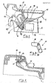
- an inspection plug (14) At the top of the second duct (10), adjacent to the outlet fitting (11) is an inspection plug (14).
- Said bowl (1) has along the upper edge and in its inner part a ring-shaped conduit (15) provided with a set of holes (16) directly open towards the inside of the bowl (1); this ring-shaped duct (15) is connected posteriorly to a chamber for the water supply (17) into which ends a supply tube (18) which, in its whole is connected to the hydraulic system for supplying water with interposition of water intake means.
- Said supply tube (18), before entering the chamber (17) has a part of the Venturi system (19) formed largely by a longitudinal internal partition (20) which shares the tube (18) in a first conduit (21) which allows the passage of water from the supply tube (18) and a second conduit (22) having an opening hole on its upper part (23).
- the lower edge (24) of this partition (20) is anyway higher by a height h relative to the upper edge of the bowl (1).
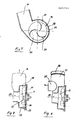
- the propeller (12) thus illustrated by sketches 7 and 8, has three wings (25) integral with a disc (26) raised in the shape of a cone in its central part (27).
- the propeller (12) contained in the chamber (19) is located away from the walls (28) of the chamber (9) in order to leave a large space (29) around it. This space is necessary to allow not only the water to pass but also to be able to evacuate any content from the bowl.
- suction duct (30) of the chamber (9) has a smaller section than that of the sending duct (31) of this same chamber (9).
- the connector (11) is of reduced size thus allowing the evacuation tube (32) to have a small section.
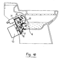
- Drawings 5 and 6 illustrate the sequence of operation of the invention.
- the water supply takes place through an electric control, according to the arrows (33), water which accumulates at the bottom of the bowl (1) up to the level of evacuation of the siphon.
- the motor (13) and the propeller (12) are activated, started by the water which is already in the chamber (9), sucks the contents of the bowl and expels it under pressure according to the direction of the arrow (34) through the discharge tube (32).
- a first advantage derives from the fact that the particular combination of siphons, a first of which feeds the propeller chamber and a second, constituted by the same propeller chamber, allows the latter to be constantly filled with useful water. self-priming; moreover the first siphon stops any odors which come from the evacuation tube even if the second siphon were to empty under the pressure effect of the propeller.
- the particular conformation of the propeller and the chamber which contains it allows an easy evacuation of the bowl without blocking or piling up.
- the presence of one or more inspection plugs allows easy intervention in the event of crowding.
- the sending conduit (31) is closed by an inspection plug (36).
- a bypass duct (35) is fixed on said sending duct to convey the flow of water to the fitting (11).
Landscapes
- Engineering & Computer Science (AREA)
- Health & Medical Sciences (AREA)
- Life Sciences & Earth Sciences (AREA)
- Hydrology & Water Resources (AREA)
- Public Health (AREA)
- Water Supply & Treatment (AREA)
- Aviation & Aerospace Engineering (AREA)
- Sanitary Device For Flush Toilet (AREA)
Applications Claiming Priority (2)
| Application Number | Priority Date | Filing Date | Title |
|---|---|---|---|
| IT4153985 | 1985-04-04 | ||
| IT8541539A IT1210167B (it) | 1985-04-04 | 1985-04-04 | Vaso sanitario perfezionato con scarico in pressione. |
Publications (2)
| Publication Number | Publication Date |
|---|---|
| EP0223764A2 true EP0223764A2 (de) | 1987-05-27 |
| EP0223764A3 EP0223764A3 (de) | 1987-08-19 |
Family
ID=11250850
Family Applications (1)
| Application Number | Title | Priority Date | Filing Date |
|---|---|---|---|
| EP86870040A Withdrawn EP0223764A3 (de) | 1985-04-04 | 1986-04-02 | Toilette mit Evakuierung unter Druck |
Country Status (2)
| Country | Link |
|---|---|
| EP (1) | EP0223764A3 (de) |
| IT (1) | IT1210167B (de) |
Cited By (4)
| Publication number | Priority date | Publication date | Assignee | Title |
|---|---|---|---|---|
| WO1995018274A1 (en) * | 1993-12-28 | 1995-07-06 | Toto Ltd. | Water closet |
| US5502845A (en) * | 1991-06-10 | 1996-04-02 | Toto Ltd. | Siphon-jet flush water supply system for toilet stool |
| FR3121692A1 (fr) | 2021-04-13 | 2022-10-14 | Aerstop Oy | Sanitaire |
| US12507842B2 (en) | 2023-02-22 | 2025-12-30 | Aerstop Oy | Toilet |
Family Cites Families (4)
| Publication number | Priority date | Publication date | Assignee | Title |
|---|---|---|---|---|
| FR1461693A (fr) * | 1965-10-29 | 1966-02-25 | Appareil de vidange | |
| FR2270395A1 (en) * | 1974-02-22 | 1975-12-05 | Lecat Roger | Flushing toilet bowl with syphon system - has outlet opening connected to combined comminuting and syphoning device |
| FR2457934A1 (fr) * | 1979-05-29 | 1980-12-26 | Piet Etablissements P | Dispositif de disconnection a pression atmospherique pour appareil de distribution d'eau |
| US4333185A (en) * | 1980-05-07 | 1982-06-08 | International Water Saving Systems, Inc. | Water saving toilet system |
-
1985
- 1985-04-04 IT IT8541539A patent/IT1210167B/it active
-
1986
- 1986-04-02 EP EP86870040A patent/EP0223764A3/de not_active Withdrawn
Cited By (5)
| Publication number | Priority date | Publication date | Assignee | Title |
|---|---|---|---|---|
| US5502845A (en) * | 1991-06-10 | 1996-04-02 | Toto Ltd. | Siphon-jet flush water supply system for toilet stool |
| WO1995018274A1 (en) * | 1993-12-28 | 1995-07-06 | Toto Ltd. | Water closet |
| FR3121692A1 (fr) | 2021-04-13 | 2022-10-14 | Aerstop Oy | Sanitaire |
| EP4074905A1 (de) | 2021-04-13 | 2022-10-19 | Aerstop OY | Sanitäranlage |
| US12507842B2 (en) | 2023-02-22 | 2025-12-30 | Aerstop Oy | Toilet |
Also Published As
| Publication number | Publication date |
|---|---|
| IT8541539A0 (it) | 1985-04-04 |
| IT1210167B (it) | 1989-09-06 |
| EP0223764A3 (de) | 1987-08-19 |
Similar Documents
| Publication | Publication Date | Title |
|---|---|---|
| CA2122165A1 (fr) | Recuperateur d'eau domestique pour usage de toilette | |
| FR2485098A1 (fr) | Dispositif d'alimentation en carburant avec retour du carburant en exces, notamment pour moteur diesel | |
| EP0561899B1 (de) | Toilette | |
| EP0230918B1 (de) | Vorrichtung zum unterirdischen Entwässern von Böden | |
| EP0223764A2 (de) | Toilette mit Evakuierung unter Druck | |
| BE883301A (fr) | Moyens de ventilation pour water-closet | |
| FR2808459A1 (fr) | Filtre exterieur a un bac, notamment a un aquarium | |
| FR2622228A1 (fr) | Perfectionnement apporte aux sieges du type comportant une cuvette a l'anglaise | |
| FR2505382A1 (fr) | Water-closet a evacuation mecanique comportant une chambre d'evacuation accessible et demontable depuis l'interieur de la cuvette du water-closet | |
| FR2702788A1 (fr) | Siège d'aisance autonettoyant. | |
| FR2965835A1 (fr) | Installation comprenant un poste de transformation electrique et un systeme ameliore de separation des eaux pluviales et de l'huile de fuite | |
| FR2919004A1 (fr) | W.c equipe de moyens d'etancheite | |
| FR2474079A1 (fr) | Siphon inodore pour ecoulements, conduites de drainage ou similaires | |
| FR2835010A1 (fr) | Procede de circulation et nettoyage de l'eau de piscines, implantation d'un systeme pour la mise en oeuvre du procede et multiplicateur de debit adapte | |
| FR1452838A (fr) | Appareil pour le renouvellement de l'air dans les réservoirs de liquide sous pression | |
| WO1995032342A1 (fr) | Perfectionnement aux cuvettes sanitaires ou analogues | |
| WO1995032342A9 (fr) | Perfectionnement aux cuvettes sanitaires ou analogues | |
| FR2747139A1 (fr) | Dispensateur de liquide dans une cuvette sanitaire | |
| FR2663373A1 (fr) | Procede et dispositif pour etablir une depression dans une zone de terrain permeable isolee de l'atmosphere par une membrane etanche. | |
| FR2744750A1 (fr) | Installation pour piscine comprenant un ensemble fonctionnel de filtration et des moyens d'acces a ladite piscine | |
| EP0484213B1 (de) | Sanitärapparat für Zwangabfluss von Abwasser | |
| FR2888860A1 (fr) | Economiseur d'eau | |
| FR2935719A1 (fr) | Dispositif d'extraction d'odeurs pour cabinet d'aisance | |
| EP0743402A1 (de) | Toilettenbrille | |
| EP1055035B1 (de) | Verbesserte vorrichtung und verfahren zum entfernen von toilettengerüchen |
Legal Events
| Date | Code | Title | Description |
|---|---|---|---|
| PUAI | Public reference made under article 153(3) epc to a published international application that has entered the european phase |
Free format text: ORIGINAL CODE: 0009012 |
|
| AK | Designated contracting states |
Kind code of ref document: A2 Designated state(s): AT BE CH DE FR GB IT LI LU NL SE |
|
| PUAL | Search report despatched |
Free format text: ORIGINAL CODE: 0009013 |
|
| AK | Designated contracting states |
Kind code of ref document: A3 Designated state(s): AT BE CH DE FR GB IT LI LU NL SE |
|
| STAA | Information on the status of an ep patent application or granted ep patent |
Free format text: STATUS: THE APPLICATION IS DEEMED TO BE WITHDRAWN |
|
| 18D | Application deemed to be withdrawn |
Effective date: 19880220 |