EP0223801B1 - Kupplungsvorrichtung zum anhängen eines gerätes auf rädern an einen traktor - Google Patents
Kupplungsvorrichtung zum anhängen eines gerätes auf rädern an einen traktor Download PDFInfo
- Publication number
- EP0223801B1 EP0223801B1 EP86903271A EP86903271A EP0223801B1 EP 0223801 B1 EP0223801 B1 EP 0223801B1 EP 86903271 A EP86903271 A EP 86903271A EP 86903271 A EP86903271 A EP 86903271A EP 0223801 B1 EP0223801 B1 EP 0223801B1
- Authority
- EP
- European Patent Office
- Prior art keywords
- tractor
- drawbar
- towing
- implement
- coupling
- Prior art date
- Legal status (The legal status is an assumption and is not a legal conclusion. Google has not performed a legal analysis and makes no representation as to the accuracy of the status listed.)
- Expired
Links
Images


Classifications
-
- A—HUMAN NECESSITIES
- A01—AGRICULTURE; FORESTRY; ANIMAL HUSBANDRY; HUNTING; TRAPPING; FISHING
- A01B—SOIL WORKING IN AGRICULTURE OR FORESTRY; PARTS, DETAILS, OR ACCESSORIES OF AGRICULTURAL MACHINES OR IMPLEMENTS, IN GENERAL
- A01B59/00—Devices specially adapted for connection between animals or tractors and agricultural machines or implements
- A01B59/04—Devices specially adapted for connection between animals or tractors and agricultural machines or implements for machines pulled or pushed by a tractor
-
- A—HUMAN NECESSITIES
- A01—AGRICULTURE; FORESTRY; ANIMAL HUSBANDRY; HUNTING; TRAPPING; FISHING
- A01D—HARVESTING; MOWING
- A01D67/00—Undercarriages or frames specially adapted for harvesters or mowers; Mechanisms for adjusting the frame; Platforms
- A01D67/005—Arrangements of coupling devices
Definitions
- This invention relates to a coupling device for connecting a wheeled agricultural implement with hydraulically driven working means and a tractor provided with mechanical power take-off
- a coupling device for connecting a wheeled agricultural implement with hydraulically driven working means and a tractor provided with mechanical power take-off
- a towing device with a coupling joint for pivotal connection with the one end of a drawbar which at its other end is pivotally connected with the implement, and having a motive power transfer from a hydraulic pump mechanically connected with the power take-off of the tractor to the working means of the implement by means of flexible hoses allowing a wide-ranging pivoting of the drawbar in the coupling joint.
- coupling devices are required which, on one hand, ensure a stable towing connection and, on the other hand, a transfer of motive power from the power take-off of the tractor to the driven working means of the implement in such a manner that the losses of transfer become as small as possible and the manoeuvring ability in field as optimum as possible so that the implement may follow the ground and the crop, thereby running through the field as rationally and quickly as possible.
- the centrally mounted towing hitch of the tractor or a towing bar between the lifting linkage is used for directly coupling the drawbar of the implement through which the towing force is transferred to the implement.
- the driving power is simultaneously transferred from the power take-off of the tractor by means of a primary, releasable power transfer shaftto a secondary power transfer shaft journalled in connection with the drawbar and connected with the working means of the implement through a universal joint.
- the primary, releasable power transfer shaft provided with two universal joints and an intermediate telescopic part is a critical point of the coupling-up.
- the coupling point between the towing device of the tractor and the drawbar must be located approximately halfway between the power take-off of the tractor and the secondary power intake of the power transfer shaft which generally includes a connecting shaft, Since a large angle of swing is at the same time desired when turning in the field, the primary power transfer shaft has to be comparatively long which gives rise to vibrations and thus to increasing wear and tear and even to damage. If the coupling point is moved from the centre of the power transfer shaft, the power transfer shaft may, for the same angle of swing, be shorter. In return, however, the maximum angular motion within the universal joints increases, whereby also wear and tear and the risk of damage increases. This problem may partly be eliminated by use of a so- called wide-angle universal joint, but this solution is still insufficient if it is desired to manoeuvre at large angles of swing.
- a coupling device is known from European patent specification 27295, according to which the towing force as well as the motive power is transferred from the tractor to the implement through a supporting unit for a mechanical transmission consisting of at least two parts mutually pivotal about a vertically extending axis, The one part of said supporting unit operates as a releasable pull connection with the tractor lifting linkage and as a journal for the input shaft of the transmission, respectively, said shaft being releasably connected to the power take-off of the tractor by means of a propeller shaft.
- the other part of the supporting unit operates as a permanent pull connection with the drawbar of the implement and as a direct or indirect journal bearing forthe output shaft of the transmission, respectively, firmly connected with a mechanical transmission jour- nailed within or along the drawbar and being in the form of a driving shaft or a belt drive transferring the motive power to the working means of the implement.
- Said prior coupling device allows for working at large angles of swing between the tractor and the drawbar of the implement without the risk of overloading the primary power transfer shaft.
- said solution is more complicated and somewhat more expensive than said conventional solution.
- the flexibility in the feed-back to the tractor is obtained to the detriment of essentially reduced margin with a view to designing the drawbar and the implement proper.
- the power intake constituted by said shaft is vertically positioned and firmly connected with the drawbar as well as with the main frame of the implement proper.
- the connecting joint between the drawbar and the implement proper may thus be placed in the position most advantageous with a view to manoeuvring, straight in front of the field of operation of the working means, without requiring a further transmission connection - as is the case with implements having mechanical transmission.
- the implement may further be provided with separate, floatingly suspended working means possessing the above specified advantages.
- said flexibility of the connection between the tractor and the implement is further provided in that the drawbar of the implement is connected with the central towing hitch of the tractor across a particular pull extension so that the drawbar is pivotally connected with the pull extension secured to the tractor at a point located behind the rearmost vertical tangential plane of the tractor.
- a coupling device for connecting a wheeled agricultural implement having hydraulically driven working means with a tractor provided with mechanical power take-off comprising a towing device with a coupling joint for permanent pivotal connection with the one end of a drawbar to allow the drawbar to pivot freely at least about an approximately vertical axis, the drawbar being pivotally connected at its other end with the implement, the towing device being adapted to be rigidly but releasably connected with the ordinary towing means of the tractor in such a manner that the coupling joint is located behind the rearmost point of the tractor, characterised by a motive power transfer from a hydraulic pump mechanically connected with the power take-off of the tractor to the working means of the implement by means of flexible hoses allowing a wide ranging pivoting of the drawbar in the coupling joint, the hydraulic pump being permanently secured to the towing device and being permanently connected with the flexible hoses to a hydraulic motor associated with the working means of the implement while it is adapted to be releasably connected with
- the coupling device may therefore also be applicable in connection with large modern agricultural implements with a heavy demand on power.
- the towing device operating as pull extension remains connected with the drawbar when the implement is not in use.
- the towing device further operates a support for the pump which then, apart from a simple mounting and dismounting of a relatively light transmission shaft, is coupled and uncoupled with the towing device.
- the weight of the towing device, the pump etc. may in this respect be transferred to the base through a supporting device mounted on the towing device or the drawbar.
- the towing device may include a fixture in the form of a sleeve or the like and adapted to be connected with the central towing yoke of the tractor, and the coupling joint may be constituted by a spherical joint allowing the drawbar to freely pivot about an approximately vertical axis and to a certain extent about an arbitrary, approximately horizontal axis.
- central towing yoke may however have unlike form and location on different tractor models, it is thus necessary to provide the towing device with additional means for individual adaptation to the respective tractor models.
- the towing device includes a supporting stirrup with bearing pins for releasable mounting in the lift arms of the tractor so that the towing device can pivot in relation thereto on an approximately horizontal axis and that the hydraulic pump is permanently secured to the supporting stirrup and adapted to be releasably connected with the power take-off of the tractor by means of a connecting shaft provided with a universal joint allowing pivoting of the hydraulic pump together with the supporting stirrup.
- the coupling device is in this preferred embodiment applicable without adaptation to various types of tractors.
- the coupling joint includes a linkage preferably connected between the supporting stirrup and the drawbar and allowing the drawbar to pivot in relation to the lift arms about a substantially vertical axis and about a horizontal axis extending substantially parallel to the lift arms.
- the hydraulic pump may be integral with a container for hydraulic liquid secured to the towing device.
- the need for making use of a long and heavy suction hose is thus eliminated which in order to minimize pressure losses must have a large diameter, the hydraulic pump being possibly accommodated within the container and coupled to the power take-off of the tractor across a short connecting shaft with a single or double universal joint.
- the advantage is obtained that the weight of the comparatively heavy container is assumed by the rear wheels of the tractor and not by the wheels of the implement.
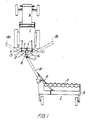
- the driving effect to the driven working means, in casu the rotor disc beam 8 of the cutter 2 is transferred hydrostatically by means of a hydraulic pump 3 releasably connected with the mechanical power take-off 4 of the tractor 1 across a connecting shaft 5 having universal joints 6 and from which a flexible hose connection 7 is established to and along a drawbar 18 to a hydraulic motor 20 accommodated within cutter 2 in driving connection with its rotor disc beam 8.
- the suction of hydraulic liquid, e.g. oil, to the pump 3 is effected from a container not shown which may be disposed on the supporting frame of the agricultural implement 2 across a suction pipe with comparatively large diameter in order to reduce the pressure as much as possible.
- a container not shown which may be disposed on the supporting frame of the agricultural implement 2 across a suction pipe with comparatively large diameter in order to reduce the pressure as much as possible.
- the towing force to the cutter 2 is transferred from the lift arms 9 and 10 of the tractor 1 across a towing device 12 through a coupling joint 17 to the drawbar 18 and further on to the cutter 2 across a coupling joint 19.
- the lift arms 9 and 10 are at their opposite free ends provided with a swivel link in which the towing device 12 may be releasably mounted by means of bearing pins 13.
- the towing device 12 includes a supporting stirrup 14 which in the illustrated embodiment is designed as an upwardly curving, substantially semi-circular tubing provided at its ends with said bearing pins 13 and approximately centrally thereof with a bearing 15 the form of which is more specifically illustrated in Fig, 6, Besides the supporting stirrup 14 the towing device 12 comprises a short connecting rod 16 slopingly directed to the rear and upwards and which at its one end is pivotally coupled to the bearing 15 and at its other end is pivotally connected with the pull rod 18 through a bearing 17.
- the short connecting rod 16 is at its ends provided with bearing yokes 21 and 22, resp., forming angles u and v with the connecting rod 16 as illustrated in Fig. 5, the total angle reaching approximately 90°.
- the bearing 15 has a substantially horizontal pivot axis parallel to the lift arms 9 and 10 and the bearing 17 has a substantially vertical pivot axis while the bearing 13 has a substantially horizontal pivot axis perpendicular to the pivot axes of the bearings 15 and 17.
- a very large area of variation for the angle of the drawbar 18 in the horizontal plane in relation to the longitudinal axis of the tractor 1 is obtained due to the location of the bearing 17 at some distance behind the free ends of the lift arms 9 and 10, said area of variation extending between the illustrated dotted marginal positions 18a and 18b of the pull rod 18.
- the theoretical area of variation is in the illustrated example about ⁇ 120°. This provides for obtaining a very little turning radius, thereby rationalizing and facilitating working in field.
- the hydraulic pump 3 is secured to a mounting plate 23 connected with the supporting stirrup 14 and the area of angular variations of the pivoting movement of the supporting stirrup 14 about the axis of rotation of the bearings 13 will therefore be determined by the universal joints 6 of the connecting shaft 5 across which the input shaft of the hydraulic pump 3 is connected with the power take-off 4 of the tractor 1.
- the pivotal connection in bearings 13 and 15 thus ensures a reasonable manoeuvring ability also in case of sloping and undulating ground.
- the rod 18 may as illustrated in Figs. 2 and 3 be embodied as a hollow profile for interior protected passage of the hose connection 7 between an inlet opening 24 and an outlet opening 25 so that the hose connection 7 is only cleared in the area between the bearing 15 and the coupling joint 17 and around the coupling joint 19 where a flexible motive power transfer is required.
- the hose connection 7 is passed from the outlet opening 25 directly to the hydraulic motor 20 coupled to the rotor disc beam 8.
- FIG. 8 shows a side view of the rearmost part of a tractor 27 with one rear wheel 28 and with a central towing yoke 29 to which the towing device is coupled.
- the towing device 30 includes a sleeve 37 to be rigidly but releasably connected with the towing yoke 29 of the tractor.
- the position of the sleeve 37 may be adjusted in relation to the remaining towing device 30 by means of a telescopically operating adjuster 38.
- the towing device 30 further accommodates a linkage in the form of a spherical joint 34 for pivotal connection with the drawbar 33 that is again connected with a wheeled agricultural implement not illustrated.
- a hydraulic pump 31 is by means of a mounting fixture 40 secured to the towing device 30 so that their mutual positions may be adjusted by means of an adjuster 39.
- the hydraulic pump 31 may by means of the adjusters 38 and 39 be secured relative to the towing device 30 in such a manner that the drive shaft 35 of the hydraulic pump 31 is approximately in alignment with the power take-off part 32 of the tractor 27 and at a certain distance therefrom. This offers the hydraulic pump 31 to be easily and reliably coupled in a releasable manner to the power take-off 32 of the tractor 27 by means of a simple, short propeller shaft 41.
- the motive power is transferred further from the hydraulic pump 31 to the implement across a pivotal hose connection 36 allowing a wide-ranging pivoting between the towing device 30 and the drawbar 33 in the coupling joint 34.
- the drawbar 33 is provided with an adjustable base plate 42 able to settle which under parking retains the implement in the parking position. During coupling and uncoupling the base plate 42 likewise transfers part of the weight of the coupling device to the base, thereby materially facilitating such work.
- Fig. 9 illustrates an embodiment in which the hydraulic pump 43 is completely integral with the container 44 and connected therewith across a very short suction pipe 45.
- the container 44 is secured directly to the towing device, e.g. between the lift arms of a transversal stirrup 46, the end of said lift arms being adapted to be connected with the lift arms 47 of the tractor.
- the releasable mechanical drive connection of the pump 43 with the power take-off 48 is, as in the embodiment in Figs 1 to 7, established across a short connecting shaft 49 with two universal joints 50.
- the hydraulic liquid is fed from the pump 43 through a flexible pressure hose 53 to the hydraulic motor, not shown, from which the liquid is fed back to the container 44 through a return hose 54 that may be carried out with a substantially smaller diameter than a suction hose, the hydraulic liquid being still under pressure in said back-feed pipe.
- a suction hose is made entirely superfluous and the connecting shaft 49a may be very short with a single universal joint 50a.
Landscapes
- Life Sciences & Earth Sciences (AREA)
- Environmental Sciences (AREA)
- Zoology (AREA)
- Engineering & Computer Science (AREA)
- Mechanical Engineering (AREA)
- Soil Sciences (AREA)
- Agricultural Machines (AREA)
Claims (8)
Applications Claiming Priority (2)
| Application Number | Priority Date | Filing Date | Title |
|---|---|---|---|
| DK2411/85 | 1985-05-30 | ||
| DK241185A DK167043B1 (da) | 1985-05-30 | 1985-05-30 | Koblingsindretning til sammenkobling af et koerbart markredskab til en traktor |
Publications (2)
| Publication Number | Publication Date |
|---|---|
| EP0223801A1 EP0223801A1 (de) | 1987-06-03 |
| EP0223801B1 true EP0223801B1 (de) | 1990-08-01 |
Family
ID=8112192
Family Applications (1)
| Application Number | Title | Priority Date | Filing Date |
|---|---|---|---|
| EP86903271A Expired EP0223801B1 (de) | 1985-05-30 | 1986-05-26 | Kupplungsvorrichtung zum anhängen eines gerätes auf rädern an einen traktor |
Country Status (5)
| Country | Link |
|---|---|
| US (1) | US4838358A (de) |
| EP (1) | EP0223801B1 (de) |
| DE (1) | DE3673131D1 (de) |
| DK (1) | DK167043B1 (de) |
| WO (1) | WO1986006927A1 (de) |
Cited By (1)
| Publication number | Priority date | Publication date | Assignee | Title |
|---|---|---|---|---|
| DE29704121U1 (de) * | 1997-03-07 | 1997-05-15 | Maschinenfabrik Rau GmbH, 73235 Weilheim | Fahrbare Spritzeinrichtung |
Families Citing this family (21)
| Publication number | Priority date | Publication date | Assignee | Title |
|---|---|---|---|---|
| US5287934A (en) * | 1988-12-02 | 1994-02-22 | Brian Porter | Soil working implement |
| FR2652705B1 (fr) * | 1989-10-11 | 1992-03-06 | Lucas Sa G | Perfectionnement au systeme d'attelage sur tracteur, d'une remorque a essieu central, et notamment une remorque agricole a chargement arriere. |
| US5335856A (en) * | 1992-10-13 | 1994-08-09 | Fmc Corporation | Air boom sprayer trailer hitch and suspension |
| US6082085A (en) * | 1998-05-13 | 2000-07-04 | Agco Corporation | Foliage mowing implement having mechanical drive with main gearbox rotation |
| CA2274288A1 (en) | 1999-06-09 | 2000-12-09 | Mcleod Harvest Inc. | Method and apparatus for harvesting crops |
| CA2332684C (en) * | 2000-12-08 | 2005-04-12 | Mcleod Harvest Inc. | Hydraulic drive line and hitching assembly for pull-type implements |
| CA2327994A1 (en) | 2000-12-08 | 2002-06-08 | Robert H. Mcleod | Hydraulic drive line for pull-type crop harvester |
| US6966388B1 (en) * | 2004-06-07 | 2005-11-22 | Cnh America Llc | Offset hitch |
| RU2297938C1 (ru) * | 2005-12-08 | 2007-04-27 | Федеральное государственное образовательное учреждение высшего профессионального образования "Воронежский государственный аграрный университет имени К.Д. Глинки" (ФГОУ ВПО ВГАУ имени К.Д. Глинки) | Сцепное устройство для соединения колесного трактора с прицепом |
| CA2538489C (en) * | 2006-02-24 | 2012-01-31 | Macdon Industries Ltd. | Connection of the hitch arm of a pull-type machine to a tractor |
| CA2538020C (en) * | 2006-02-24 | 2012-08-21 | Macdon Industries Ltd. | Hydraulic drive arrangement for the cutter of a pull-type crop harvesting machine |
| NL1036352C2 (nl) * | 2008-12-22 | 2010-06-23 | Lely Patent Nv | Tophef aankoppeling. |
| NL1037742C2 (en) * | 2010-02-23 | 2011-08-24 | Forage Innovations Bv | Wrapper for wrapping bales of crop material. |
| FR2961721B1 (fr) * | 2010-06-28 | 2013-03-08 | Chambre D Agriculture Du Gard | Dispositif de nettoyage de machine agricole. |
| DE102010041885A1 (de) * | 2010-10-01 | 2012-04-05 | Deere & Company | Kombination aus einem Zugfahrzeug und einem Gerät |
| US8096571B1 (en) * | 2010-10-12 | 2012-01-17 | Richard Dale Noe | Tractor hitch assembly and trailer with hydraulic pump |
| ITPD20120330A1 (it) * | 2012-11-06 | 2014-05-07 | Maschio Gaspardo Spa | Dispositivo di aggancio per attrezzature agricole trainate |
| EP3008985B1 (de) * | 2014-10-15 | 2017-08-09 | Kverneland Group Ravenna S.r.l. | Schleppvorrichtung für landwirtschaftliche Maschinen wie etwa Ballenpressen, Rundballenpressen und dergleichen |
| US10231372B2 (en) * | 2017-02-24 | 2019-03-19 | Matthew S. Pennybacker | Coupling device to connect two tractor-pulled agricultural implements for tandem-powered operation |
| US10926969B1 (en) * | 2020-06-05 | 2021-02-23 | James P. Shea | Roller arm assembly for temporary tape removal machine |
| CN115289145B (zh) * | 2022-08-12 | 2025-11-28 | 乌鲁木齐优尼克生物科技有限公司 | 一种液压泵连接器 |
Family Cites Families (15)
| Publication number | Priority date | Publication date | Assignee | Title |
|---|---|---|---|---|
| US1496999A (en) * | 1922-04-03 | 1924-06-10 | Charles H Ray | Tractor harvester transmission |
| US1661737A (en) * | 1925-08-17 | 1928-03-06 | Raimer Philip | Tractor trailer connection |
| US2171761A (en) * | 1937-06-04 | 1939-09-05 | Deere & Co | Mower |
| US2569507A (en) * | 1945-10-27 | 1951-10-02 | Schlegell Frederick Von | Hydraulic operating system for mowing machines |
| GB828029A (en) * | 1956-10-23 | 1960-02-10 | Aage Moustgaard | Improvements in mechanical transmission means for transmitting torque from the power take off shaft of a tractor |
| FR1187344A (fr) * | 1957-11-29 | 1959-09-09 | Dispositif d'attache et de transmission entre un tracteur et une moissonneusebroyeuse | |
| NL6503955A (de) * | 1965-03-29 | 1966-09-30 | ||
| FR1563090A (de) * | 1968-02-23 | 1969-04-11 | ||
| US3665685A (en) * | 1970-07-06 | 1972-05-30 | Jean Allard | Mowing device for cutting vegetation adjacent a fence |
| GB1379601A (en) * | 1971-03-01 | 1975-01-02 | Mccormack P D | Apparatus for cleaning and trimming back verges of unkerbed roads |
| US3715872A (en) * | 1971-07-19 | 1973-02-13 | P Thompson | Mowing apparatus |
| BE792147A (fr) * | 1971-12-03 | 1973-03-16 | Mulag Fahrzeug Woessner | Engin faucheur aspirateur |
| NL7907546A (nl) * | 1979-10-11 | 1981-04-14 | Multinorm Bv | Vermogen-overbrengende koppelinrichting bij een trekker en daaraan gekoppeld werktuig. |
| EP0090879A1 (de) * | 1982-01-21 | 1983-10-12 | B. Strautmann & Söhne GmbH & Co. | Hydraulische Antriebseinrichtung für landwirtschaftliches Arbeitsgerät |
| US4584826A (en) * | 1983-02-23 | 1986-04-29 | Blackwelders | Tomato harvester |
-
1985
- 1985-05-30 DK DK241185A patent/DK167043B1/da not_active IP Right Cessation
-
1986
- 1986-05-26 EP EP86903271A patent/EP0223801B1/de not_active Expired
- 1986-05-26 WO PCT/DK1986/000057 patent/WO1986006927A1/en not_active Ceased
- 1986-05-26 US US07/014,065 patent/US4838358A/en not_active Expired - Fee Related
- 1986-05-26 DE DE8686903271T patent/DE3673131D1/de not_active Expired - Fee Related
Cited By (1)
| Publication number | Priority date | Publication date | Assignee | Title |
|---|---|---|---|---|
| DE29704121U1 (de) * | 1997-03-07 | 1997-05-15 | Maschinenfabrik Rau GmbH, 73235 Weilheim | Fahrbare Spritzeinrichtung |
Also Published As
| Publication number | Publication date |
|---|---|
| DK167043B1 (da) | 1993-08-23 |
| WO1986006927A1 (en) | 1986-12-04 |
| US4838358A (en) | 1989-06-13 |
| EP0223801A1 (de) | 1987-06-03 |
| DE3673131D1 (de) | 1990-09-06 |
| DK241185A (da) | 1986-12-01 |
| DK241185D0 (da) | 1985-05-30 |
Similar Documents
| Publication | Publication Date | Title |
|---|---|---|
| EP0223801B1 (de) | Kupplungsvorrichtung zum anhängen eines gerätes auf rädern an einen traktor | |
| US4899523A (en) | Mower | |
| US5094063A (en) | Mower including a group of working elements extending crosswise to a direction of advance at work | |
| US4330981A (en) | Towable ganged mower | |
| US4719742A (en) | Mowing machine | |
| US5355971A (en) | Drivetrain and load bearing swivel hitch assembly and combine incorporating same | |
| US5901533A (en) | Agricultural machine | |
| EP1825736B1 (de) | Verbindung zwischen Schlepper und Zugarm einer gezogenen Erntemaschine | |
| US5076042A (en) | Mowing machine | |
| US5473872A (en) | Angled drive for an agriculural header assembly | |
| EP2055169A2 (de) | Antriebssystem für eine Landwirtschaftsmaschine mit schwimmendem Arbeitswerkzeug | |
| US20040070172A1 (en) | Offset arm for towing rotary mowers and the like | |
| EP1347676B1 (de) | Hydraulikantrieb und anhängevorrichtung für anhängegerät | |
| US7334645B2 (en) | Articulated power transfer apparatus | |
| US11116124B2 (en) | Implement offset arm | |
| US6003291A (en) | Agriculture machine | |
| US4648472A (en) | Tractor for agricultural purposes | |
| US5265403A (en) | Draft tongue for connecting PTO-driven implement to draft links of a towing vehicle | |
| US6129372A (en) | Self-propelled agricultural implement | |
| US11997938B2 (en) | Articulated apparatus for towing a rotary driven implement from a towing vehicle | |
| US10231372B2 (en) | Coupling device to connect two tractor-pulled agricultural implements for tandem-powered operation | |
| US6464016B2 (en) | Hitch system | |
| CA2136498C (en) | Angled drive for an agricultural header assembly | |
| EP0006302A1 (de) | Fahrzeug mit hydraulischem Antrieb | |
| CA1183355B (en) | Swather |
Legal Events
| Date | Code | Title | Description |
|---|---|---|---|
| PUAI | Public reference made under article 153(3) epc to a published international application that has entered the european phase |
Free format text: ORIGINAL CODE: 0009012 |
|
| 17P | Request for examination filed |
Effective date: 19870218 |
|
| AK | Designated contracting states |
Kind code of ref document: A1 Designated state(s): BE CH DE FR GB LI NL |
|
| 17Q | First examination report despatched |
Effective date: 19880308 |
|
| GRAA | (expected) grant |
Free format text: ORIGINAL CODE: 0009210 |
|
| AK | Designated contracting states |
Kind code of ref document: B1 Designated state(s): BE CH DE FR GB LI NL |
|
| PG25 | Lapsed in a contracting state [announced via postgrant information from national office to epo] |
Ref country code: LI Effective date: 19900801 Ref country code: CH Effective date: 19900801 Ref country code: BE Effective date: 19900801 |
|
| REF | Corresponds to: |
Ref document number: 3673131 Country of ref document: DE Date of ref document: 19900906 |
|
| ET | Fr: translation filed | ||
| REG | Reference to a national code |
Ref country code: CH Ref legal event code: PL |
|
| PLBE | No opposition filed within time limit |
Free format text: ORIGINAL CODE: 0009261 |
|
| STAA | Information on the status of an ep patent application or granted ep patent |
Free format text: STATUS: NO OPPOSITION FILED WITHIN TIME LIMIT |
|
| 26N | No opposition filed | ||
| PGFP | Annual fee paid to national office [announced via postgrant information from national office to epo] |
Ref country code: GB Payment date: 19990513 Year of fee payment: 14 |
|
| PGFP | Annual fee paid to national office [announced via postgrant information from national office to epo] |
Ref country code: FR Payment date: 19990521 Year of fee payment: 14 |
|
| PGFP | Annual fee paid to national office [announced via postgrant information from national office to epo] |
Ref country code: NL Payment date: 19990531 Year of fee payment: 14 |
|
| PGFP | Annual fee paid to national office [announced via postgrant information from national office to epo] |
Ref country code: DE Payment date: 19990721 Year of fee payment: 14 |
|
| PG25 | Lapsed in a contracting state [announced via postgrant information from national office to epo] |
Ref country code: GB Free format text: LAPSE BECAUSE OF NON-PAYMENT OF DUE FEES Effective date: 20000526 |
|
| PG25 | Lapsed in a contracting state [announced via postgrant information from national office to epo] |
Ref country code: NL Free format text: LAPSE BECAUSE OF NON-PAYMENT OF DUE FEES Effective date: 20001201 |
|
| GBPC | Gb: european patent ceased through non-payment of renewal fee |
Effective date: 20000526 |
|
| PG25 | Lapsed in a contracting state [announced via postgrant information from national office to epo] |
Ref country code: FR Free format text: LAPSE BECAUSE OF NON-PAYMENT OF DUE FEES Effective date: 20010131 |
|
| NLV4 | Nl: lapsed or anulled due to non-payment of the annual fee |
Effective date: 20001201 |
|
| PG25 | Lapsed in a contracting state [announced via postgrant information from national office to epo] |
Ref country code: DE Free format text: LAPSE BECAUSE OF NON-PAYMENT OF DUE FEES Effective date: 20010301 |
|
| REG | Reference to a national code |
Ref country code: FR Ref legal event code: ST |