EP0223898B1 - Dispositif hydrauliquede compensation de jeu - Google Patents
Dispositif hydrauliquede compensation de jeu Download PDFInfo
- Publication number
- EP0223898B1 EP0223898B1 EP86102711A EP86102711A EP0223898B1 EP 0223898 B1 EP0223898 B1 EP 0223898B1 EP 86102711 A EP86102711 A EP 86102711A EP 86102711 A EP86102711 A EP 86102711A EP 0223898 B1 EP0223898 B1 EP 0223898B1
- Authority
- EP
- European Patent Office
- Prior art keywords
- spherical
- adjusting piston
- sliding shoe
- valve
- valve stem
- Prior art date
- Legal status (The legal status is an assumption and is not a legal conclusion. Google has not performed a legal analysis and makes no representation as to the accuracy of the status listed.)
- Expired
Links
- 230000002093 peripheral effect Effects 0.000 claims 3
- 230000000717 retained effect Effects 0.000 claims 1
- 238000009434 installation Methods 0.000 description 1
- 238000005461 lubrication Methods 0.000 description 1
Images

Classifications
-
- F—MECHANICAL ENGINEERING; LIGHTING; HEATING; WEAPONS; BLASTING
- F01—MACHINES OR ENGINES IN GENERAL; ENGINE PLANTS IN GENERAL; STEAM ENGINES
- F01L—CYCLICALLY OPERATING VALVES FOR MACHINES OR ENGINES
- F01L1/00—Valve-gear or valve arrangements, e.g. lift-valve gear
- F01L1/46—Component parts, details, or accessories, not provided for in preceding subgroups
-
- F—MECHANICAL ENGINEERING; LIGHTING; HEATING; WEAPONS; BLASTING
- F01—MACHINES OR ENGINES IN GENERAL; ENGINE PLANTS IN GENERAL; STEAM ENGINES
- F01L—CYCLICALLY OPERATING VALVES FOR MACHINES OR ENGINES
- F01L1/00—Valve-gear or valve arrangements, e.g. lift-valve gear
- F01L1/20—Adjusting or compensating clearance
- F01L1/22—Adjusting or compensating clearance automatically, e.g. mechanically
- F01L1/24—Adjusting or compensating clearance automatically, e.g. mechanically by fluid means, e.g. hydraulically
- F01L1/2411—Adjusting or compensating clearance automatically, e.g. mechanically by fluid means, e.g. hydraulically by means of a hydraulic adjusting device located between the valve stem and rocker arm
-
- F—MECHANICAL ENGINEERING; LIGHTING; HEATING; WEAPONS; BLASTING
- F01—MACHINES OR ENGINES IN GENERAL; ENGINE PLANTS IN GENERAL; STEAM ENGINES
- F01L—CYCLICALLY OPERATING VALVES FOR MACHINES OR ENGINES
- F01L1/00—Valve-gear or valve arrangements, e.g. lift-valve gear
- F01L1/12—Transmitting gear between valve drive and valve
- F01L1/18—Rocking arms or levers
- F01L2001/187—Clips, e.g. for retaining rocker arm on pivot
Definitions
- the invention relates to a hydraulic lash adjuster, in which a hydraulic compensation element is housed in a bore of a rocker arm or similar actuating element extending in the extension of the shaft of an engine valve, the longitudinally displaceable adjusting piston of which ends in a spherical projection towards the valve stem, between which and the flat end face of the valve stem Sliding shoe is arranged, which on the one hand has a spherical cap in which the spherical projection of the adjusting piston engages, and which on the other hand is supported with a flat surface on the end face of the valve stem.
- sliding shoes serve to create contact surfaces between the adjusting piston on the one hand and the valve stem on the other hand, by means of which wear is reduced and the lubrication conditions are improved.
- a sliding block is simply inserted between the spherical projection of the adjusting piston and the end face of the valve stem, where it is held in place during operation by the meshing of the spherical projection and the spherical cap.
- such a slide shoe has already been provided with a captive lock by allowing it to engage with a flanged edge in a circumferential groove in the valve stem. As a result, it is securely attached to the end of the valve stem when the rocker arms are removed and cannot be lost.
- the disadvantage here is that the engine manufacturer has to keep different valves in stock if he also produces valve controls with mechanical valve clearance adjustment in addition to valve controls with hydraulic lash adjusters (DE-OS 33 04 398).
- Brackets for such sliding shoes have also already been made, which are to be regarded as a kind of reversal of the previously described embodiment, in which the sliding shoe engages behind a reduction in diameter of the spherical projection on the adjusting piston with a flange.
- the invention has for its object to provide a secure mounting of the slide shoe on the hydraulic compensating element, without the need for an extension of the adjusting piston, and without changes to the valve stem being required.
- a cage part extends from a point lying behind the ball projection, which extends in the direction of the valve stem and ends there in radially inwardly directed holding zones which cover the outer lateral surface of the slide shoe or projections of this lateral surface in such a way reach behind that the sliding shoe is held captive against the adjusting piston with free angular mobility.
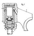
- a hydraulic compensating element 2 is mounted in the rocker arm 1 in a known manner, the adjusting piston 3 of which ends in a ball projection 5 at its end facing the valve stem 4.
- the sliding block 7 is arranged, in whose spherical cap 8 the spherical projection 5 of the adjusting piston 3 engages, and the flat end face 9 of which cooperates with the end face 6 of the valve stem 4.
- the outer surface of the sliding shoe 7 has a radially projecting collar 10 at its end facing the adjusting piston 3.
- a cage part 11 is molded into its circumferential groove 12 at its upper end for attachment to the adjusting piston 3.
- the cage part 11 is drawn in to the holding zones 13, which lie on an inner diameter which is smaller than the diameter of the collar 10.
- the distance of the holding zones 13 from the collar 10 in the axial direction is chosen so that the slide shoe 7 can pivot within the angular movements occurring during operation without hitting the holding zones 13. In this way, a secure mounting of the slide shoe 7 is ensured without its free adjustability being hindered by any adjacent components.
- the variant of the subject of the application shown in FIG. 2 differs from that of FIG. 1 only in that the slide shoe 14 provided here has an outer circumferential surface 15 which is formed as part of a spherical surface, the center of which coincides with the center of the spherical projection 5.
- the holding zones 13 of the cage part 11 end below the transverse plane 16 passing through the center of the spherical projection, as a result of which secure holding of the sliding block 14 and its free angular mobility is ensured.
Landscapes
- Engineering & Computer Science (AREA)
- Mechanical Engineering (AREA)
- General Engineering & Computer Science (AREA)
- Valve-Gear Or Valve Arrangements (AREA)
Claims (4)
Applications Claiming Priority (2)
| Application Number | Priority Date | Filing Date | Title |
|---|---|---|---|
| DE19853541198 DE3541198A1 (de) | 1985-11-21 | 1985-11-21 | Hydraulische spielausgleichsvorrichtung |
| DE3541198 | 1985-11-21 |
Publications (2)
| Publication Number | Publication Date |
|---|---|
| EP0223898A1 EP0223898A1 (fr) | 1987-06-03 |
| EP0223898B1 true EP0223898B1 (fr) | 1989-11-08 |
Family
ID=6286493
Family Applications (1)
| Application Number | Title | Priority Date | Filing Date |
|---|---|---|---|
| EP86102711A Expired EP0223898B1 (fr) | 1985-11-21 | 1986-03-01 | Dispositif hydrauliquede compensation de jeu |
Country Status (4)
| Country | Link |
|---|---|
| US (1) | US4708103A (fr) |
| EP (1) | EP0223898B1 (fr) |
| JP (1) | JPH0668241B2 (fr) |
| DE (2) | DE3541198A1 (fr) |
Families Citing this family (27)
| Publication number | Priority date | Publication date | Assignee | Title |
|---|---|---|---|---|
| DE3614258A1 (de) * | 1986-04-26 | 1987-10-29 | Motomak | Hydraulische ventilspielausgleichsvorrichtung fuer verbrennungsmotoren |
| DE3638202A1 (de) * | 1986-11-08 | 1988-05-19 | Schaeffler Waelzlager Kg | Hydraulisches spielausgleichselement |
| US4806040A (en) * | 1987-02-12 | 1989-02-21 | Cummins Engine Company, Inc. | Ceramic ball and socket joint |
| DE3706006A1 (de) * | 1987-02-25 | 1988-09-08 | Schaeffler Waelzlager Kg | Hydraulisches spielausgleichselement fuer ventilsteuerungen an verbrennungsmotoren |
| DE3725245A1 (de) * | 1987-07-30 | 1989-02-09 | Schaeffler Waelzlager Kg | Kugelgelenk, welches zwischen einen kipphebel und einen ventilschaft eines verbrennungsmotors eingeschaltet ist |
| US4815424A (en) * | 1988-03-11 | 1989-03-28 | Eaton Corporation | Hydraulic lash adjuster |
| JPH02126005U (fr) * | 1989-03-28 | 1990-10-17 | ||
| DE4446552A1 (de) * | 1994-12-24 | 1996-06-27 | Schaeffler Waelzlager Kg | Hydraulische Spielausgleichsvorrichtung |
| DE19502497A1 (de) * | 1995-01-27 | 1996-08-01 | Schaeffler Waelzlager Kg | Hydraulische Spielausgleichsvorrichtung |
| DE19505406A1 (de) * | 1995-02-17 | 1996-08-22 | Schaeffler Waelzlager Kg | Hydraulische Spielausgleichsvorrichtung |
| US5632237A (en) * | 1995-08-07 | 1997-05-27 | Hy-Lift Division Of Spx Corporation | Hydraulic lash compensating element assembly |
| DE19537641A1 (de) * | 1995-10-10 | 1997-04-17 | Bayerische Motoren Werke Ag | Punktgelagerter Schwing- oder Kipphebel |
| US5680838A (en) * | 1996-10-21 | 1997-10-28 | General Motors Corporation | Swivel foot lash adjuster |
| US5706771A (en) | 1996-12-23 | 1998-01-13 | General Motors Corporation | Hydraulic element assembly |
| DE19733027A1 (de) * | 1997-07-31 | 1999-02-04 | Schaeffler Waelzlager Ohg | Hydraulische Ventilspielausgleichsvorrichtung |
| DE19750806B4 (de) * | 1997-11-17 | 2015-03-26 | Schaeffler Technologies AG & Co. KG | Hydraulische Spielausgleichsvorrichtung |
| US6138624A (en) * | 1999-03-01 | 2000-10-31 | Cummins Engine Company, Inc. | Tappet socket assembly for rocker lever assembly and method of assembling the same |
| US6148780A (en) * | 1999-03-31 | 2000-11-21 | Delphi Technologies, Inc. | Hydraulic element assembly |
| US6273042B1 (en) * | 1999-06-14 | 2001-08-14 | Amsted Industries Incorporated | Rocker assemblies for control of engine valves and method of assembling such rocker assemblies |
| US6397805B1 (en) | 1999-06-28 | 2002-06-04 | Michael G. Knickerbocker | Retainer for rocker arm coupling in an internal combustion engine |
| US6199526B1 (en) * | 1999-06-28 | 2001-03-13 | Michael G. Knickerbocker | Retainer for rocker arm coupling in an internal combustion engine |
| US6557507B2 (en) | 2001-03-30 | 2003-05-06 | Caterpillar Inc. | Rocker arm assembly |
| US8006661B2 (en) * | 2009-08-04 | 2011-08-30 | International Engine Intellectual Property Company, Llc | Bridge and pivot foot arrangement for operating engine cylinder valves |
| DE102011002592A1 (de) | 2011-01-12 | 2012-07-12 | Schaeffler Technologies Gmbh & Co. Kg | Winkelgelenk |
| FR2976617B1 (fr) * | 2011-06-15 | 2015-06-19 | Valeo Sys Controle Moteur Sas | Controle d'un moteur a combustion interne |
| DE102012200755A1 (de) | 2012-01-19 | 2013-07-25 | Schaeffler Technologies AG & Co. KG | Hydraulische Spielausgleichsvorrichtung |
| GB2542600A (en) * | 2015-09-25 | 2017-03-29 | Eaton Srl | Hydraulic lash adjuster |
Family Cites Families (11)
| Publication number | Priority date | Publication date | Assignee | Title |
|---|---|---|---|---|
| US1865998A (en) * | 1929-10-23 | 1932-07-05 | Jr Adrian O Abbott | Valve operating assembly |
| US2051313A (en) * | 1933-08-14 | 1936-08-18 | Boyle Motor Products Company | Valve attachment |
| DE1179763B (de) * | 1960-09-14 | 1964-10-15 | Ford Werke Ag | Ventiltrieb fuer ueber Stoessel, Stoesselstangen und Kipphebel gesteuerte Ventile von Brenn-kraftmaschinen |
| US3137282A (en) * | 1962-08-23 | 1964-06-16 | Voorhies Carl | Metering valve with pin |
| GB1369597A (en) * | 1970-10-17 | 1974-10-09 | Snell A J | Valve gear |
| DE2843918C2 (de) * | 1978-10-09 | 1980-12-18 | Ford-Werke Ag, 5000 Koeln | Hydraulischer Stößel für einen Ventiltrieb einer Brennkraftmaschine |
| DE2920075A1 (de) * | 1979-05-18 | 1980-11-20 | Kloeckner Humboldt Deutz Ag | Ventilgesteuerte brennkraftmaschine |
| DE3118466A1 (de) * | 1981-05-09 | 1982-11-25 | Motomak Motorenbau, Maschinen- u. Werkzeugfabrik, Konstruktionen GmbH, 8070 Ingolstadt | Kipp- oder schwinghebel einer brennkraftmaschine |
| DE3203791A1 (de) * | 1982-02-04 | 1983-08-11 | Volkswagenwerk Ag, 3180 Wolfsburg | Ventiltrieb, insbesondere fuer eine kraftfahrzeug-brennkraftmaschine |
| JPS58122710U (ja) * | 1982-02-16 | 1983-08-20 | 宇部興産株式会社 | 排気弁駆動用タペツト |
| DE3304398A1 (de) * | 1983-02-09 | 1984-08-09 | Motomak Motorenbau, Maschinen- u. Werkzeugfabrik, Konstruktionen GmbH, 8070 Ingolstadt | Innenelement fuer ein hydraulisches ventilspielausgleichselement fuer verbrennungsmotoren |
-
1985
- 1985-11-21 DE DE19853541198 patent/DE3541198A1/de not_active Withdrawn
-
1986
- 1986-03-01 EP EP86102711A patent/EP0223898B1/fr not_active Expired
- 1986-03-01 DE DE8686102711T patent/DE3666857D1/de not_active Expired
- 1986-06-02 US US06/869,432 patent/US4708103A/en not_active Expired - Lifetime
- 1986-07-08 JP JP61158902A patent/JPH0668241B2/ja not_active Expired - Lifetime
Also Published As
| Publication number | Publication date |
|---|---|
| DE3541198A1 (de) | 1987-05-27 |
| DE3666857D1 (en) | 1989-12-14 |
| US4708103A (en) | 1987-11-24 |
| JPH0668241B2 (ja) | 1994-08-31 |
| JPS62126211A (ja) | 1987-06-08 |
| EP0223898A1 (fr) | 1987-06-03 |
Similar Documents
| Publication | Publication Date | Title |
|---|---|---|
| EP0223898B1 (fr) | Dispositif hydrauliquede compensation de jeu | |
| EP0244558B1 (fr) | Dispositif hydraulique de compensation du jeu des soupapes pour un moteur à combustion interne | |
| EP0301267B1 (fr) | Rotule située entre un culbuteur et une tige de soupape d'un moteur à combustion interne | |
| DE19749761A1 (de) | Entkoppelte Riemenscheibe | |
| DE202004012604U1 (de) | Kugelgelenk | |
| EP0280888B1 (fr) | Compensateur hydraulique de jeu pour la commande de soupapes des moteurs à combustion interne | |
| DE10142329A1 (de) | Ventiltrieb für eine Brennkraftmaschine | |
| DE3224762C2 (fr) | ||
| DE3330141A1 (de) | Ventilsteuerung fuer brennkraftmaschinen | |
| DE4204630C2 (de) | Kugelraste für die Lagefixierung eines beweglichen Stellelementes | |
| DE9405694U1 (de) | Schlepphebel für einen Ventiltrieb einer Brennkraftmaschine | |
| DE4118776A1 (de) | Mechanischer ventilstoessel fuer eine brennkraftmaschine | |
| EP1623747B1 (fr) | Filtre annulaire pour des rainures annulaire | |
| DE4337330C2 (de) | Rollenstößel mit zwei Rollen je Ventil für Ventiltriebe von Verbrennungsmotoren mit oben liegender Nockenwelle | |
| DE3643673C2 (fr) | ||
| DE3920243C2 (de) | Gelenkverbindung | |
| DE19537641A1 (de) | Punktgelagerter Schwing- oder Kipphebel | |
| DE19750806B4 (de) | Hydraulische Spielausgleichsvorrichtung | |
| DE19544412C1 (de) | Ventiltrieb einer Brennkraftmaschine | |
| DE19903850B4 (de) | Rastvorrichtung für die Lagefixierung der Dreh- oder Längsbewegung einer Schaltwelle | |
| DE4118370A1 (de) | Lagegesicherter ventilbetaetigungs-stoessel | |
| DE19529041B4 (de) | Kipp- oder Schlepphebelanordnung | |
| DE931076C (de) | Zwangsweise arbeitende Ventildreheinrichtung, insbesondere fuer Brennkraftmaschinen | |
| DE4104611A1 (de) | Waelzlager | |
| DE19504315A1 (de) | Abdichtungsvorrichtung für Wälzlager, insbesondere für Kraftfahrzeug-Radnaben |
Legal Events
| Date | Code | Title | Description |
|---|---|---|---|
| PUAI | Public reference made under article 153(3) epc to a published international application that has entered the european phase |
Free format text: ORIGINAL CODE: 0009012 |
|
| 17P | Request for examination filed |
Effective date: 19860314 |
|
| AK | Designated contracting states |
Kind code of ref document: A1 Designated state(s): DE FR GB IT |
|
| 17Q | First examination report despatched |
Effective date: 19880527 |
|
| ITF | It: translation for a ep patent filed | ||
| GRAA | (expected) grant |
Free format text: ORIGINAL CODE: 0009210 |
|
| AK | Designated contracting states |
Kind code of ref document: B1 Designated state(s): DE FR GB IT |
|
| GBT | Gb: translation of ep patent filed (gb section 77(6)(a)/1977) | ||
| REF | Corresponds to: |
Ref document number: 3666857 Country of ref document: DE Date of ref document: 19891214 |
|
| ET | Fr: translation filed | ||
| PLBE | No opposition filed within time limit |
Free format text: ORIGINAL CODE: 0009261 |
|
| STAA | Information on the status of an ep patent application or granted ep patent |
Free format text: STATUS: NO OPPOSITION FILED WITHIN TIME LIMIT |
|
| 26N | No opposition filed | ||
| ITTA | It: last paid annual fee | ||
| PGFP | Annual fee paid to national office [announced via postgrant information from national office to epo] |
Ref country code: GB Payment date: 19940221 Year of fee payment: 9 |
|
| PGFP | Annual fee paid to national office [announced via postgrant information from national office to epo] |
Ref country code: FR Payment date: 19940307 Year of fee payment: 9 |
|
| PG25 | Lapsed in a contracting state [announced via postgrant information from national office to epo] |
Ref country code: GB Effective date: 19950301 |
|
| GBPC | Gb: european patent ceased through non-payment of renewal fee |
Effective date: 19950301 |
|
| PG25 | Lapsed in a contracting state [announced via postgrant information from national office to epo] |
Ref country code: FR Free format text: LAPSE BECAUSE OF NON-PAYMENT OF DUE FEES Effective date: 19951130 |
|
| REG | Reference to a national code |
Ref country code: FR Ref legal event code: ST |
|
| PG25 | Lapsed in a contracting state [announced via postgrant information from national office to epo] |
Ref country code: IT Free format text: LAPSE BECAUSE OF NON-PAYMENT OF DUE FEES;WARNING: LAPSES OF ITALIAN PATENTS WITH EFFECTIVE DATE BEFORE 2007 MAY HAVE OCCURRED AT ANY TIME BEFORE 2007. THE CORRECT EFFECTIVE DATE MAY BE DIFFERENT FROM THE ONE RECORDED. Effective date: 20050301 |
|
| PGFP | Annual fee paid to national office [announced via postgrant information from national office to epo] |
Ref country code: DE Payment date: 20050903 Year of fee payment: 20 |