EP0223923A2 - Rétroviseur extérieur pour véhicule - Google Patents
Rétroviseur extérieur pour véhicule Download PDFInfo
- Publication number
- EP0223923A2 EP0223923A2 EP86110687A EP86110687A EP0223923A2 EP 0223923 A2 EP0223923 A2 EP 0223923A2 EP 86110687 A EP86110687 A EP 86110687A EP 86110687 A EP86110687 A EP 86110687A EP 0223923 A2 EP0223923 A2 EP 0223923A2
- Authority
- EP
- European Patent Office
- Prior art keywords
- mirror
- housing
- base
- rotating member
- mirror base
- Prior art date
- Legal status (The legal status is an assumption and is not a legal conclusion. Google has not performed a legal analysis and makes no representation as to the accuracy of the status listed.)
- Withdrawn
Links
Images
Classifications
-
- B—PERFORMING OPERATIONS; TRANSPORTING
- B60—VEHICLES IN GENERAL
- B60R—VEHICLES, VEHICLE FITTINGS, OR VEHICLE PARTS, NOT OTHERWISE PROVIDED FOR
- B60R1/00—Optical viewing arrangements; Real-time viewing arrangements for drivers or passengers using optical image capturing systems, e.g. cameras or video systems specially adapted for use in or on vehicles
- B60R1/02—Rear-view mirror arrangements
- B60R1/06—Rear-view mirror arrangements mounted on vehicle exterior
- B60R1/076—Rear-view mirror arrangements mounted on vehicle exterior yieldable to excessive external force and provided with an indexed use position
Definitions
- the invention relates to a vehicle exterior mirror with a mirror base to be fastened to the vehicle and a mirror housing which is attached to the mirror base and can be pivoted about a substantially vertical axis and in which an adjustable mirror glass is arranged.
- the exterior mirrors of vehicles must be adjustable to enable the field of vision to be adapted to the respective driver position. It is known to arrange the mirror housing on the vehicle side in the case of vehicle exterior mirrors and to fix the mirror glass to an adjustable mirror carrier which can be pivoted about two axes within the mirror housing.
- the safety regulations require that the mirror housing is attached to the vehicle in a foldable manner and can be pivoted onto the body when an impact hits the mirror housing.
- the adjustment and folding options mentioned are generally available for vehicle mirrors; however, the invention is concerned with another problem which occurs with mirrors of the type mentioned: the vehicle exterior mirrors are produced as a driver-side left mirror and as a passenger-side right mirror, both of which are adjusted to the position of the driver. This means that the driver's left mirror protrudes from the vehicle at almost a right angle, while the right mirror has a smaller angle of attack. The housings of the left and right mirrors therefore have different angles of attack in relation to the vehicle's longitudinal direction. If such mirrors are now also to be used for vehicles with right-hand drive, two further mirror types are required, because then the mirror housing of the left mirror must have a smaller angle of attack to the vehicle body than the mirror housing of the right mirror. For vehicles that are delivered both with right-hand drive and with left-hand drive, a total of four different mirror types must be provided and kept ready.
- the invention has for its object to provide a vehicle exterior mirror of the type mentioned, which can perform both the function of the driver's side mirror and that of the passenger side mirror as a left-hand mirror and can also perform both functions as a right-hand mirror.
- a lockable adjusting device is located between the mirror base or a rotating element fixed in place on the mirror base and the mirror housing is provided, which allows adjustment of the mirror housing to two different pivot positions.
- the vehicle exterior mirror according to the invention can e.g. can be used as a left-hand mirror as both a driver-side and a passenger-side mirror, with the mirror housing being set to a different swivel position.
- the two swivel positions usually differ by an angle of approximately 15 °.
- For vehicles that are optionally equipped with right-hand drive or left-hand drive only two different mirror types are required, provided two exterior mirrors are provided.
- each exterior mirror can be adjusted either as a driver's side or as a passenger's side mirror. The setting once selected is permanently fixed.
- the invention is generally applicable to such vehicle exterior mirrors in which the mirror housing normally protrudes from the body at a fixed angle, ie in those mirrors in which not the entire mirror housing, but only the mirror glass within the mirror housing is adjusted for individual adjustment to the driver position .
- the state in which the mirror housing is mounted relative to the vehicle body can be selected, regardless of whether the mirrors can be folded down.
- the problem underlying the invention does not occur in mirrors in which the entire mirror housing is infinitely adjustable for adjustment to the driver position. This problem arises only when the mirror housing is in the operating state (in the unfolded state) protrudes from the body at a predetermined fixed angle. This fixed angle can be set using the adjustment device.
- a particular advantage is that regardless of whether the mirror is used as a driver's side mirror or as a passenger's mirror, a limited pivoting range of the mirror glass within the mirror housing is sufficient to make the adjustment to the driver's position. This is due to the fact that the mirror housing is set in advance to the respective function of the mirror and that only individual settings then have to be made in relation to the driver, but not in relation to the driver's seat arrangement.
- a swivel limiting device is provided between the mirror base or a rotating member fixed in place on the mirror base and the end stops corresponding to the two swivel positions.
- the swivel limiting device facilitates adjustment to one of the two swivel positions in which the adjusting device is effective.
- the mirror base can have a hollow tube on which a cap-shaped rotating member sits; the rotary organ dips into a recess in the mirror housing; an elastic tensioning device pulls the rotating member and the mirror housing against the mirror base and interlocking locking elements are provided on the rotating member and the mirror base.
- the rotating member forms a device that enables the mirror to be folded down onto the vehicle body and during the subsequent one Resetting the mirror causes the mirror housing to snap back into the normal position.
- the tensioning device has a hollow shaft which extends from the mirror housing into the mirror base. Cables can be inserted from the mirror base into the mirror housing in a concealed manner through the tubular hollow shaft in order to supply an electrical de-icing device and / or an electrical adjusting device with current. The cable is hidden through the interior of the joint that connects the mirror housing with the mirror base. This ensures that the cable does not have to be passed outside the joint.
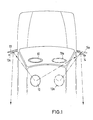
- the steering wheel 10 is shown in solid lines in a left-hand drive vehicle.
- the driver's head is designated by 12.
- the housing of the driver-side mirror 13 projects from the vehicle body almost at right angles.
- the right mirror 14 has a larger inclination than the left mirror 13, i.e. the angle that the mirror housing forms with the vehicle body is more acute than with the mirror 13.
- the exemplary embodiment described below relates to the right-hand mirror 14 or 14a, the housing of which can be adjusted to the two positions shown.
- the left-hand mirror can also be designed in the same way.
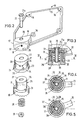
- Fig. 2 only the mirror housing 15 is shown of the mirror 14; the mirror glass and the mirror glass support and the adjustment device for adjusting the Mirror glass in relation to the mirror housing 15 has been omitted for reasons of clarity.
- the outer edge of the mirror housing 15 is also not shown.
- the adjustment drive and the pivot bearing for the mirror glass support are fastened to fastening devices 16 in the interior of the mirror housing 15.
- the mirror housing 15 has a bearing part 17 with a cylindrical recess 18 with a vertical axis.
- the recess 18 is delimited at the top by a horizontal wall 19 which has a hole 20 for pushing through the shaft 21.
- the shaft can also be designed as a hollow rivet. In this case the mother 29 would be omitted.
- the cap-shaped cylindrical rotary member 37 protrudes into the recess 18 from below, the upper wall 22 of which lies against the wall 19 from below.
- the rotating member 37 has at the lower end a radially projecting flange 23 which engages under the edge of the bearing part 17. There are radial grooves 24 in the underside of the flange 23.
- the rigid mirror base 25 mounted on the vehicle is provided with an upstanding cylinder 26 which projects into the interior of the rotary member 37 and has a horizontal wall 27 at its upper end.
- the shaft 21 projects through mutually aligned holes in the walls 19, 22 and 27 and extends into the interior of the cylinder 26.
- the shaft 21 is supported on the wall 19 by a head 21a.
- a helical spring 28 surrounding the shaft 21 inside the cylinder 26 presses against the underside of the wall 27 and is supported at the opposite end by a nut 29 which is screwed onto a thread of the shaft 21.
- the spring 28 therefore presses the walls 27, 22 and 19 axially against one another.
- the mirror base 25 is provided at the lower end of the cylinder 26 with a radial flange 30, on the upper side of which radial ribs 31 are provided.
- Each of the ribs 31 is received by one of the grooves 24 of the rotary member 37. Due to the action of the spring 28, the grooves 24 are pressed over the ribs 31.
- the grooves 24 and the ribs 31 form interlocking latching elements which are pressed against one another under the action of the spring 28 in order to hold the mirror in position. In the event of a blow acting against the mirror housing, the latching elements can disengage and the mirror housing can be folded onto the vehicle body.
- the adjusting device comprising the screw 32 and the two locking holes 33, 34 is provided.
- the screw 32 is screwed into a radial threaded bore in the wall of the bearing part 17 and its end protrudes into one of the two bores 33 or 34 of the rotary member 21.
- the bores 33 and 34 are arranged on the rotating member 37 at the same height and they are at an angular distance of approximately 15 ° from one another.
- the pivot limiting device 35, 36 serves to make it easier to find the pivot position. This consists of the pin 35 protruding from the upper side of the flange 23 of the rotary member 37 and the circumferential groove 36 provided on the underside of the wall of the bearing part 17.
- the pin 35 projects into the groove 36 and is displaceable therein.
- the ends of the groove 36 form end stops. When the pin 35 abuts one end of the groove 36, the screw 32 is in alignment with one of the holes 33 or 34.
- the grooves 24 snap out of the webs 31.
- the grooves snap back into the webs.
- the possibility of setting the mirror housing to two different angular positions in connection with a folding mechanism has been described. If a folding mechanism is not present, the adjusting device is effective directly between the mirror base and the mirror housing, while in the presence of a folding mechanism it is effective between the rotating member 21 which is latchingly connected to the mirror base and the mirror housing.
Landscapes
- Engineering & Computer Science (AREA)
- Multimedia (AREA)
- Mechanical Engineering (AREA)
- Rear-View Mirror Devices That Are Mounted On The Exterior Of The Vehicle (AREA)
Applications Claiming Priority (2)
| Application Number | Priority Date | Filing Date | Title |
|---|---|---|---|
| DE8533057U | 1985-11-23 | ||
| DE19858533057 DE8533057U1 (de) | 1985-11-23 | 1985-11-23 | Fahrzeugaußenspiegel |
Publications (2)
| Publication Number | Publication Date |
|---|---|
| EP0223923A2 true EP0223923A2 (fr) | 1987-06-03 |
| EP0223923A3 EP0223923A3 (fr) | 1988-05-18 |
Family
ID=6787535
Family Applications (1)
| Application Number | Title | Priority Date | Filing Date |
|---|---|---|---|
| EP86110687A Withdrawn EP0223923A3 (fr) | 1985-11-23 | 1986-08-01 | Rétroviseur extérieur pour véhicule |
Country Status (2)
| Country | Link |
|---|---|
| EP (1) | EP0223923A3 (fr) |
| DE (1) | DE8533057U1 (fr) |
Cited By (8)
| Publication number | Priority date | Publication date | Assignee | Title |
|---|---|---|---|---|
| GB2186246B (en) * | 1986-02-10 | 1989-11-08 | Michael Zipperle | External rear view mirror for motor vehicles |
| US5073019A (en) * | 1989-01-10 | 1991-12-17 | Metagal Industria E Comercio Ltda. | External rear view mirror assembly for vehicles |
| US5205182A (en) * | 1991-02-04 | 1993-04-27 | Britax Rainsfords Pty Ltd | Cable actuated mirror tilt control |
| EP0644084A1 (fr) * | 1993-09-03 | 1995-03-22 | Ichikoh Industries Limited | Système de miroir rétroviseur pour véhicules automobiles |
| US5636071A (en) * | 1994-08-25 | 1997-06-03 | Murakami Kaimeido Co., Ltd. | Speed reduction device for an electrically powered foldable rearview mirror |
| US5639054A (en) * | 1994-11-02 | 1997-06-17 | United Technologies Automotive Systems, Inc. | Pivot mount for exterior side-mounted rearview mirror |
| CN102811886A (zh) * | 2010-03-23 | 2012-12-05 | 戴姆勒股份公司 | 车辆外后视镜对 |
| CN116513051A (zh) * | 2023-05-06 | 2023-08-01 | 吕巷汽车零部件江苏有限公司 | 一种具有防撞击功能的后视镜角度调节装置 |
Families Citing this family (2)
| Publication number | Priority date | Publication date | Assignee | Title |
|---|---|---|---|---|
| DE19922797B4 (de) * | 1999-05-18 | 2006-11-02 | Bayerische Motoren Werke Ag | Außenrückblickspiegel für ein Kraftfahrzeug |
| DE102008026039B4 (de) * | 2008-05-30 | 2012-12-13 | Ficosa International Gmbh | Rückspiegel und Verfahren zum Montieren eines Rückspiegels an einem Kraftwagen |
Family Cites Families (3)
| Publication number | Priority date | Publication date | Assignee | Title |
|---|---|---|---|---|
| DE3017228A1 (de) * | 1980-05-06 | 1981-11-12 | Bernhard Dipl.-Wirtsch.-Ing. 3002 Wedemark Mittelhäuser | Aussenrueckblickspiegel fuer kraftfahrzeuge |
| DE3268988D1 (en) * | 1981-10-22 | 1986-03-20 | Britax Wingard Ltd | Exterior rear view mirror |
| DE3433513A1 (de) * | 1984-09-12 | 1986-03-20 | ASE Deutschland GmbH, 7100 Heilbronn | Schwenkhalterung fuer einen fahrzeugteil |
-
1985
- 1985-11-23 DE DE19858533057 patent/DE8533057U1/de not_active Expired
-
1986
- 1986-08-01 EP EP86110687A patent/EP0223923A3/fr not_active Withdrawn
Cited By (10)
| Publication number | Priority date | Publication date | Assignee | Title |
|---|---|---|---|---|
| GB2186246B (en) * | 1986-02-10 | 1989-11-08 | Michael Zipperle | External rear view mirror for motor vehicles |
| US5073019A (en) * | 1989-01-10 | 1991-12-17 | Metagal Industria E Comercio Ltda. | External rear view mirror assembly for vehicles |
| US5205182A (en) * | 1991-02-04 | 1993-04-27 | Britax Rainsfords Pty Ltd | Cable actuated mirror tilt control |
| EP0644084A1 (fr) * | 1993-09-03 | 1995-03-22 | Ichikoh Industries Limited | Système de miroir rétroviseur pour véhicules automobiles |
| US6132050A (en) * | 1993-09-03 | 2000-10-17 | Ichikoh Industries, Ltd. | Rearview mirror system for vehicles |
| US5636071A (en) * | 1994-08-25 | 1997-06-03 | Murakami Kaimeido Co., Ltd. | Speed reduction device for an electrically powered foldable rearview mirror |
| US5639054A (en) * | 1994-11-02 | 1997-06-17 | United Technologies Automotive Systems, Inc. | Pivot mount for exterior side-mounted rearview mirror |
| CN102811886A (zh) * | 2010-03-23 | 2012-12-05 | 戴姆勒股份公司 | 车辆外后视镜对 |
| US9079538B2 (en) | 2010-03-23 | 2015-07-14 | Daimler Ag | Pair of external vehicle mirrors |
| CN116513051A (zh) * | 2023-05-06 | 2023-08-01 | 吕巷汽车零部件江苏有限公司 | 一种具有防撞击功能的后视镜角度调节装置 |
Also Published As
| Publication number | Publication date |
|---|---|
| EP0223923A3 (fr) | 1988-05-18 |
| DE8533057U1 (de) | 1986-01-09 |
Similar Documents
| Publication | Publication Date | Title |
|---|---|---|
| DE4211674C2 (de) | Lenksäule mit einem Sicherheitsglied für ein im Lenkrad mit einem aufblasbaren Gassack ausgerüstetes Kraftfahrzeug | |
| DE68917443T2 (de) | Rückspiegel für Kraftfahrzeuge. | |
| DE68903867T2 (de) | Scharnier fuer eine kraftfahrzeugtuer und verfahren zum befestigen solch eines scharniers an einem kraftfahrzeug. | |
| DE29803816U1 (de) | Notenständer | |
| DE3943137A1 (de) | Traeger zur einstellung der hoehe, des schwenkwinkels und der neigung einer anzeigeeinrichtung | |
| DE7833365U1 (de) | Klemmvorrichtung zur halterung einer verstellbaren steuersaeule fuer ein kraftfahrzeug | |
| DE19934739B4 (de) | Lenkvorrichtung für ein Fahrzeug | |
| EP0223923A2 (fr) | Rétroviseur extérieur pour véhicule | |
| DE69715998T2 (de) | Fahrzeug mit drehbarem Kotflügel | |
| EP3332995B1 (fr) | Flèche d'attelage pour une remorque de véhicule | |
| DE3016212A1 (de) | Laengen- und neigungsverstellbare lenksaeule fuer ein fahrzeug | |
| DE19636719A1 (de) | Lenkbare Starrachse für ein Kraftfahrzeug | |
| DE102005056837B4 (de) | Einrichtung zum Befestigen eines fahrerseitigen Airbagmoduls in einem Fahrzeug | |
| EP0221255A2 (fr) | Rétroviseur pour véhicule | |
| EP0092665B1 (fr) | Dispositif de fixation pour le bras d'un rétroviseur extérieur de véhicule utilitaire | |
| EP0437695A1 (fr) | Rétroviseur extérieur auxiliaire pour véhicules automobiles | |
| EP0802083A2 (fr) | Rétroviseur extérieur | |
| DE102019131595B4 (de) | Fahrzeugsitz | |
| EP0901927B1 (fr) | Trappe d'obturation pour couvrir la tubulure de remplissage pour véhicules automobiles | |
| DE2426489A1 (de) | Rueckblickspiegel fuer kraftfahrzeuge o.dgl. | |
| DE69804009T2 (de) | Verfahren zum befestigen von verstellvorrichtungen in fahrzeug-rückblickspiegel, montageplatte dafür, und spiegel mit solcher platte | |
| DE3605945C2 (de) | Aussenrückblickspiegel für Kraftfahrzeuge | |
| DE3339436A1 (de) | Vorrichtung zur einstellung der position eines fahrzeugsitzes | |
| DE2303688A1 (de) | Rueckblickspiegel | |
| DE2024118A1 (fr) |
Legal Events
| Date | Code | Title | Description |
|---|---|---|---|
| PUAI | Public reference made under article 153(3) epc to a published international application that has entered the european phase |
Free format text: ORIGINAL CODE: 0009012 |
|
| AK | Designated contracting states |
Kind code of ref document: A2 Designated state(s): AT DE FR GB IT NL SE |
|
| PUAL | Search report despatched |
Free format text: ORIGINAL CODE: 0009013 |
|
| AK | Designated contracting states |
Kind code of ref document: A3 Designated state(s): AT DE FR GB IT NL SE |
|
| 17P | Request for examination filed |
Effective date: 19881028 |
|
| STAA | Information on the status of an ep patent application or granted ep patent |
Free format text: STATUS: THE APPLICATION HAS BEEN WITHDRAWN |
|
| 17Q | First examination report despatched |
Effective date: 19900918 |
|
| 18W | Application withdrawn |
Withdrawal date: 19901018 |
|
| RIN1 | Information on inventor provided before grant (corrected) |
Inventor name: LUCHTENBERG, CURT |