EP0223954A1 - Inductance pour redresseur commandé, en particulier pour installations de transmission de courant continu à haute tension - Google Patents
Inductance pour redresseur commandé, en particulier pour installations de transmission de courant continu à haute tension Download PDFInfo
- Publication number
- EP0223954A1 EP0223954A1 EP86112961A EP86112961A EP0223954A1 EP 0223954 A1 EP0223954 A1 EP 0223954A1 EP 86112961 A EP86112961 A EP 86112961A EP 86112961 A EP86112961 A EP 86112961A EP 0223954 A1 EP0223954 A1 EP 0223954A1
- Authority
- EP
- European Patent Office
- Prior art keywords
- winding
- feature
- core
- valve throttle
- primary winding
- Prior art date
- Legal status (The legal status is an assumption and is not a legal conclusion. Google has not performed a legal analysis and makes no representation as to the accuracy of the status listed.)
- Granted
Links
- 230000005540 biological transmission Effects 0.000 title claims description 5
- 238000009434 installation Methods 0.000 title 1
- 238000004804 winding Methods 0.000 claims abstract description 45
- 239000000872 buffer Substances 0.000 claims abstract description 3
- 238000005538 encapsulation Methods 0.000 claims abstract 2
- 238000001816 cooling Methods 0.000 claims description 16
- 238000005266 casting Methods 0.000 claims description 9
- 238000004382 potting Methods 0.000 claims description 6
- RYGMFSIKBFXOCR-UHFFFAOYSA-N Copper Chemical compound [Cu] RYGMFSIKBFXOCR-UHFFFAOYSA-N 0.000 claims description 4
- 239000004020 conductor Substances 0.000 claims description 4
- 229910052802 copper Inorganic materials 0.000 claims description 4
- 239000010949 copper Substances 0.000 claims description 4
- 239000002826 coolant Substances 0.000 claims description 2
- 150000001875 compounds Chemical class 0.000 claims 1
- 238000013016 damping Methods 0.000 claims 1
- 238000009413 insulation Methods 0.000 abstract description 3
- 238000004519 manufacturing process Methods 0.000 abstract description 3
- 238000000034 method Methods 0.000 abstract 1
- 238000005520 cutting process Methods 0.000 description 5
- 239000010410 layer Substances 0.000 description 2
- 239000000463 material Substances 0.000 description 2
- 230000007704 transition Effects 0.000 description 2
- 230000035508 accumulation Effects 0.000 description 1
- 238000009825 accumulation Methods 0.000 description 1
- 238000005352 clarification Methods 0.000 description 1
- 229940125773 compound 10 Drugs 0.000 description 1
- 238000010276 construction Methods 0.000 description 1
- 230000001419 dependent effect Effects 0.000 description 1
- 238000005516 engineering process Methods 0.000 description 1
- 230000017525 heat dissipation Effects 0.000 description 1
- ZLVXBBHTMQJRSX-VMGNSXQWSA-N jdtic Chemical compound C1([C@]2(C)CCN(C[C@@H]2C)C[C@H](C(C)C)NC(=O)[C@@H]2NCC3=CC(O)=CC=C3C2)=CC=CC(O)=C1 ZLVXBBHTMQJRSX-VMGNSXQWSA-N 0.000 description 1
- 230000035515 penetration Effects 0.000 description 1
- 230000002265 prevention Effects 0.000 description 1
- 239000004065 semiconductor Substances 0.000 description 1
- 239000002356 single layer Substances 0.000 description 1
- 229910001220 stainless steel Inorganic materials 0.000 description 1
- 239000010935 stainless steel Substances 0.000 description 1
Images

Classifications
-
- H—ELECTRICITY
- H01—ELECTRIC ELEMENTS
- H01F—MAGNETS; INDUCTANCES; TRANSFORMERS; SELECTION OF MATERIALS FOR THEIR MAGNETIC PROPERTIES
- H01F27/00—Details of transformers or inductances, in general
- H01F27/28—Coils; Windings; Conductive connections
- H01F27/30—Fastening or clamping coils, windings, or parts thereof together; Fastening or mounting coils or windings on core, casing, or other support
- H01F27/306—Fastening or mounting coils or windings on core, casing or other support
-
- H—ELECTRICITY
- H01—ELECTRIC ELEMENTS
- H01F—MAGNETS; INDUCTANCES; TRANSFORMERS; SELECTION OF MATERIALS FOR THEIR MAGNETIC PROPERTIES
- H01F27/00—Details of transformers or inductances, in general
- H01F27/08—Cooling; Ventilating
- H01F27/10—Liquid cooling
-
- H—ELECTRICITY
- H01—ELECTRIC ELEMENTS
- H01F—MAGNETS; INDUCTANCES; TRANSFORMERS; SELECTION OF MATERIALS FOR THEIR MAGNETIC PROPERTIES
- H01F38/00—Adaptations of transformers or inductances for specific applications or functions
- H01F38/18—Rotary transformers
Definitions
- the invention relates to a valve throttle for high-voltage direct current transmission systems.
- HVDC systems are generally used today to distribute electrical energy as a link between two three-phase systems; network-controlled controllable semiconductors (thyristors) convert the three-phase current on the transmitting side for transmission into direct current and on the receiving side back into three-phase current.
- thyristors network-controlled controllable semiconductors
- the highest achievable thyristor voltage is small compared to the valve voltage necessary for economical transmission.
- a large number of thyristors must therefore be connected in series for an HVDC valve.
- a valve choke with a liquid-cooled choke coil and choke core is also connected in series with the individual thyristors.
- each HVDC valve consists of a larger or smaller number of identical thyristor and throttle modules, which are combined in a tower-like manner in a tower base frame, depending on the voltage to be controlled.
- a compact valve throttle should be able to be created with simple manufacturing technology, which can nevertheless ensure the insulation strength and freedom from partial discharge required for all load cases between the components which are under different voltages.
- the arrangement of the entire choke coil winding in a potting block held in a frame by means of mounting pins and thus contact-free to only one leg of the self-potted choke core allows a high level of insulation and maximum creepage distances with a compact and easy-to-assemble construction, and thus a high degree of freedom from partial discharge as well as very good cooling properties.
- a particularly high degree of compactness, in particular a low overall height, can be achieved for the choke coil mounted on only one leg of the choke core in that it has two layers with a first winding part and a second winding part concentric therewith and with a core potential center connection approximately in the center of the winding, i.e. in the transition from the first winding part is provided for the second winding part; as a result, the voltage stress between the choke core and the choke winding, which is supported in a cantilever manner to one leg of the choke core, can be reduced to half the nominal voltage, and the maximum necessary clearance or creepage distance can also be reduced by half.
- the particularly good possibility of heat dissipation also contributes to the compactness of the valve throttle according to the invention, in particular due to the casting a cooling pipe through which the cooling medium flows to the surrounding primary winding and, on the other hand, the non-potting of the choke core, material accumulations and thus the risk of increased material tensions due to different temperature expansion coefficients being advantageously avoided in comparison with valve chokes with an integrally molded choke coil and choke core.
- the clamping frame which is used on the one hand for fastening the throttle core and on the other hand for the self-supporting mounting of the choke coil, is made of plastic, which, in addition to a simple specific shape for the mounting receptacles, also results in additional losses in the sense of great compactness of the valve throttle can be reduced by stray fields.
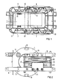
- a cutting band throttle core 5 In a ribbed plastic tenter frame 6, the most important parts of the valve throttle are a cutting band throttle core 5 and a casting block 1, into which a primary winding 2, 3 and a secondary winding 4 are cast.
- the double U-shaped cutting band throttle core 5 held together by tensioning straps 52 is held in the tensioning frame 6 by means of tie rods 51.
- One left leg of the cutting band choke core 5 is encased without contact by the casting block 1, in which the primary winding 2, 3 and the secondary winding 4 are cast.
- the casting block 1 is supported in the clamping frame 6 in a cantilever manner to the left leg of the cutting band throttle core 5.
- Rubber buffers 7 serve as lower receptacles, while funnel-shaped depressions 11 are cast into the casting block 1 as upper receptacles, engage in the stud screws 8, the penetration depth of which can be adjusted relative to the clamping frame 6 and can be fixed after the desired setting depth has been reached.
- the primary winding 2, 3 of the choke coil is wound in two layers with a first winding part 2 with the outer connection 21 and and a second inner winding part 3 concentric with it, with an outer connection 31 and a core potential center connection M in the middle of the winding, ie in the transition area from the outer first winding part 2 to the inner second winding part 3.
- a single-layer secondary winding 4 protrudes from the casting block 1 with its outer connections 41, 42.
- a water-flowed stainless steel cooling tube 9 with the outer connections 91, 92 serves to cool the primary winding 2, 3; for better thermal contact between the cooling tube 9 and the secondary winding 2, 3, which is expediently surrounding in the form of an upright wound copper hollow profile conductor is the space between the cooling tube 9 and the primary winding - as can be seen from the partial section in the left part of Figure 2 - also filled with a potting compound 10.
- the cooling tube provided here within the primary winding, which is preferably designed as a hollow profile with a cooling tube running inside the hollow profile, it can also be ensured by expanding the pressure of the cooling tube or by shrinking the hollow profile onto the cooling tube that this is in particularly good thermal contact with the primary winding.
- the leg of the cutting band choke core 5 encompassed by the potting block 1 is held in contact-free distance from the potting block 1 on all sides, so that compared to the usual windings wedged on the choke core, the dimensions are much higher in comparison Partial discharges exist or the throttle module can be built much more compactly with the same good prevention of partial discharges.
Landscapes
- Engineering & Computer Science (AREA)
- Power Engineering (AREA)
- Coils Of Transformers For General Uses (AREA)
- Rectifiers (AREA)
- Power Conversion In General (AREA)
Priority Applications (1)
| Application Number | Priority Date | Filing Date | Title |
|---|---|---|---|
| AT86112961T ATE45438T1 (de) | 1985-10-01 | 1986-09-19 | Ventildrossel, insbesondere fuer hochspannungsgleichstrom-¨bertragungsanlagen. |
Applications Claiming Priority (2)
| Application Number | Priority Date | Filing Date | Title |
|---|---|---|---|
| DE3535018 | 1985-10-01 | ||
| DE3535018 | 1985-10-01 |
Publications (2)
| Publication Number | Publication Date |
|---|---|
| EP0223954A1 true EP0223954A1 (fr) | 1987-06-03 |
| EP0223954B1 EP0223954B1 (fr) | 1989-08-09 |
Family
ID=6282479
Family Applications (1)
| Application Number | Title | Priority Date | Filing Date |
|---|---|---|---|
| EP86112961A Expired EP0223954B1 (fr) | 1985-10-01 | 1986-09-19 | Inductance pour redresseur commandé, en particulier pour installations de transmission de courant continu à haute tension |
Country Status (6)
| Country | Link |
|---|---|
| US (1) | US4775848A (fr) |
| EP (1) | EP0223954B1 (fr) |
| JP (1) | JPS6286706A (fr) |
| AT (1) | ATE45438T1 (fr) |
| DE (1) | DE3664973D1 (fr) |
| IN (1) | IN163747B (fr) |
Cited By (2)
| Publication number | Priority date | Publication date | Assignee | Title |
|---|---|---|---|---|
| EP0459326A1 (fr) * | 1990-06-01 | 1991-12-04 | ABBPATENT GmbH | Bobine de self refroidie par liquide |
| US5682292A (en) * | 1993-05-10 | 1997-10-28 | Siemens Aktiengesellschaft | Liquid-cooled valve reactor |
Citations (10)
| Publication number | Priority date | Publication date | Assignee | Title |
|---|---|---|---|---|
| US2264057A (en) * | 1940-08-21 | 1941-11-25 | Gen Electric | Coil support for electrical induction apparatus |
| GB630353A (en) * | 1947-09-18 | 1949-10-11 | Gen Electric Co Ltd | Improvements in or relating to electric inductances |
| US2579522A (en) * | 1946-02-04 | 1951-12-25 | Ohio Crankshaft Co | Transformer construction |
| US2699531A (en) * | 1950-09-02 | 1955-01-11 | Bendix Aviat Corp | Transformer core mounting |
| DE1137148B (de) * | 1959-11-04 | 1962-09-27 | Siemens Ag | Haltevorrichtung fuer Ringkernpaare, vorzugsweise fuer Magnetverstaerker |
| FR2106643A5 (en) * | 1970-09-18 | 1972-05-05 | Anvar | High tension power supply - for linear accelerator ion source |
| DE2554142A1 (de) * | 1975-11-28 | 1977-06-02 | Siemens Ag | Anordnung mit induktiven spannungswandlern |
| DE2642111A1 (de) * | 1976-09-18 | 1978-03-23 | Bosch Gmbh Robert | Scheibenfoermiger leistungstransformator fuer die induktive erwaermung von metallischen werkstuecken |
| EP0050432A1 (fr) * | 1980-10-03 | 1982-04-28 | Ford Motor Company Limited | Transformateur |
| DE3404457A1 (de) * | 1984-02-08 | 1985-08-08 | Siemens AG, 1000 Berlin und 8000 München | Einrichtung zur kuehlung eines magnetsystems |
Family Cites Families (11)
| Publication number | Priority date | Publication date | Assignee | Title |
|---|---|---|---|---|
| US3258728A (en) * | 1966-06-28 | Electrical coil and lead wire assembly | ||
| US1471096A (en) * | 1919-05-08 | 1923-10-16 | Gen Electric | Electrical apparatus |
| US1789229A (en) * | 1929-03-09 | 1931-01-13 | Wired Radio Inc | Inductance coil |
| US2413195A (en) * | 1942-12-21 | 1946-12-24 | Pacific Electric Mfg Corp | High potential current transformer means |
| US2464029A (en) * | 1945-04-07 | 1949-03-08 | Gen Electric | Method of making transformers |
| US2988715A (en) * | 1958-09-02 | 1961-06-13 | Zenith Radio Corp | Sweep transformer |
| FR1564936A (fr) * | 1968-03-15 | 1969-04-25 | ||
| DE2133987C3 (de) * | 1971-07-08 | 1974-04-25 | Aeg-Elotherm Gmbh, 5630 Remscheidhasten | Mittelfrequenz-Leistungstransformator mit einer einwindigen Sekundärwicklung |
| GB1470902A (en) * | 1975-02-28 | 1977-04-21 | Tioxide Group Ltd | Electrical series reactor |
| DE2554143A1 (de) * | 1975-11-28 | 1977-06-02 | Siemens Ag | Spannungswandler fuer hohe spannungen |
| DE3100419C2 (de) * | 1981-01-09 | 1986-07-17 | ANT Nachrichtentechnik GmbH, 7150 Backnang | Übertrager hoher Leistungsdichte |
-
1986
- 1986-07-31 IN IN583/CAL/86A patent/IN163747B/en unknown
- 1986-09-19 DE DE8686112961T patent/DE3664973D1/de not_active Expired
- 1986-09-19 EP EP86112961A patent/EP0223954B1/fr not_active Expired
- 1986-09-19 AT AT86112961T patent/ATE45438T1/de not_active IP Right Cessation
- 1986-09-29 JP JP61231085A patent/JPS6286706A/ja active Pending
- 1986-09-30 US US06/913,812 patent/US4775848A/en not_active Expired - Fee Related
Patent Citations (10)
| Publication number | Priority date | Publication date | Assignee | Title |
|---|---|---|---|---|
| US2264057A (en) * | 1940-08-21 | 1941-11-25 | Gen Electric | Coil support for electrical induction apparatus |
| US2579522A (en) * | 1946-02-04 | 1951-12-25 | Ohio Crankshaft Co | Transformer construction |
| GB630353A (en) * | 1947-09-18 | 1949-10-11 | Gen Electric Co Ltd | Improvements in or relating to electric inductances |
| US2699531A (en) * | 1950-09-02 | 1955-01-11 | Bendix Aviat Corp | Transformer core mounting |
| DE1137148B (de) * | 1959-11-04 | 1962-09-27 | Siemens Ag | Haltevorrichtung fuer Ringkernpaare, vorzugsweise fuer Magnetverstaerker |
| FR2106643A5 (en) * | 1970-09-18 | 1972-05-05 | Anvar | High tension power supply - for linear accelerator ion source |
| DE2554142A1 (de) * | 1975-11-28 | 1977-06-02 | Siemens Ag | Anordnung mit induktiven spannungswandlern |
| DE2642111A1 (de) * | 1976-09-18 | 1978-03-23 | Bosch Gmbh Robert | Scheibenfoermiger leistungstransformator fuer die induktive erwaermung von metallischen werkstuecken |
| EP0050432A1 (fr) * | 1980-10-03 | 1982-04-28 | Ford Motor Company Limited | Transformateur |
| DE3404457A1 (de) * | 1984-02-08 | 1985-08-08 | Siemens AG, 1000 Berlin und 8000 München | Einrichtung zur kuehlung eines magnetsystems |
Cited By (2)
| Publication number | Priority date | Publication date | Assignee | Title |
|---|---|---|---|---|
| EP0459326A1 (fr) * | 1990-06-01 | 1991-12-04 | ABBPATENT GmbH | Bobine de self refroidie par liquide |
| US5682292A (en) * | 1993-05-10 | 1997-10-28 | Siemens Aktiengesellschaft | Liquid-cooled valve reactor |
Also Published As
| Publication number | Publication date |
|---|---|
| ATE45438T1 (de) | 1989-08-15 |
| JPS6286706A (ja) | 1987-04-21 |
| EP0223954B1 (fr) | 1989-08-09 |
| DE3664973D1 (en) | 1989-09-14 |
| US4775848A (en) | 1988-10-04 |
| IN163747B (fr) | 1988-11-05 |
Similar Documents
| Publication | Publication Date | Title |
|---|---|---|
| DE19515003C2 (de) | Supraleitende Spule | |
| DE69512217T2 (de) | Direktwirkendes berührungloses elektrisches leistungskabel | |
| EP0698277B1 (fr) | Bobine de self pour tube refroidie par liquide | |
| DE10304606B3 (de) | Transformator zur Erzeugung hoher elektrischer Ströme | |
| DE10037379A1 (de) | Modular aufgebauter Stromrichter | |
| EP0557549B1 (fr) | Transformateur à noyau annulaire | |
| DE4008417C2 (de) | Vorrichtung zur Verbindung der elektrischen Anschlüsse von Kondensatoren | |
| EP1423903B1 (fr) | Moteur electrique equipe d'un systeme de refroidissement | |
| DE3590224T1 (de) | Leistungstransformator für integrierte Höchstgeschwindigkeitsschaltungen | |
| DE69308592T2 (de) | Gasgekühlte durchführung in kryotanks für anwendungen bei supraleitern | |
| EP0223954B1 (fr) | Inductance pour redresseur commandé, en particulier pour installations de transmission de courant continu à haute tension | |
| DE4023687A1 (de) | Stromrichteranordnung | |
| DE4141516A1 (de) | Elektrischer impulsgenerator mit saettigbarer induktanz | |
| DE8527970U1 (de) | Ventildrossel, insbesondere für Hochspannungs-Gleichstrom-Übertragungsanlagen | |
| DE3928223C2 (de) | Magnetische Einrichtung für eine Hochspannungsimpulsgeneratorvorrichtung | |
| EP1554741B1 (fr) | Boitier en materiau isolant presentant un profil interieur rainure | |
| DE2417125B2 (de) | Leistungstransformator | |
| EP0015488A1 (fr) | Colonne de thyristors | |
| EP0124809B1 (fr) | Composant inductif | |
| DE19723958C2 (de) | Spannverband | |
| DE935918C (de) | Transformator mit zwischen Scheibenspulen angeordneten Abstuetzungen | |
| DE19627817A1 (de) | Flachspule | |
| DE69320983T2 (de) | Stromverteilung zwischen mehreren strängen einer supraleitenden wicklung | |
| DE3040412C2 (de) | Wicklungsanordnung für Transformatoren | |
| DE19726563A1 (de) | Elektrische Maschine |
Legal Events
| Date | Code | Title | Description |
|---|---|---|---|
| PUAI | Public reference made under article 153(3) epc to a published international application that has entered the european phase |
Free format text: ORIGINAL CODE: 0009012 |
|
| 17P | Request for examination filed |
Effective date: 19870407 |
|
| AK | Designated contracting states |
Kind code of ref document: A1 Designated state(s): AT CH DE FR GB IT LI SE |
|
| 17Q | First examination report despatched |
Effective date: 19881107 |
|
| GRAA | (expected) grant |
Free format text: ORIGINAL CODE: 0009210 |
|
| AK | Designated contracting states |
Kind code of ref document: B1 Designated state(s): AT CH DE FR GB IT LI SE |
|
| REF | Corresponds to: |
Ref document number: 45438 Country of ref document: AT Date of ref document: 19890815 Kind code of ref document: T |
|
| PGFP | Annual fee paid to national office [announced via postgrant information from national office to epo] |
Ref country code: AT Payment date: 19890825 Year of fee payment: 4 |
|
| PGFP | Annual fee paid to national office [announced via postgrant information from national office to epo] |
Ref country code: SE Payment date: 19890912 Year of fee payment: 4 |
|
| REF | Corresponds to: |
Ref document number: 3664973 Country of ref document: DE Date of ref document: 19890914 |
|
| PGFP | Annual fee paid to national office [announced via postgrant information from national office to epo] |
Ref country code: FR Payment date: 19890928 Year of fee payment: 4 |
|
| ET | Fr: translation filed | ||
| ITF | It: translation for a ep patent filed | ||
| GBT | Gb: translation of ep patent filed (gb section 77(6)(a)/1977) | ||
| PGFP | Annual fee paid to national office [announced via postgrant information from national office to epo] |
Ref country code: DE Payment date: 19891127 Year of fee payment: 4 |
|
| PGFP | Annual fee paid to national office [announced via postgrant information from national office to epo] |
Ref country code: CH Payment date: 19891218 Year of fee payment: 4 |
|
| PLBE | No opposition filed within time limit |
Free format text: ORIGINAL CODE: 0009261 |
|
| STAA | Information on the status of an ep patent application or granted ep patent |
Free format text: STATUS: NO OPPOSITION FILED WITHIN TIME LIMIT |
|
| 26N | No opposition filed | ||
| PG25 | Lapsed in a contracting state [announced via postgrant information from national office to epo] |
Ref country code: GB Effective date: 19900919 Ref country code: AT Effective date: 19900919 |
|
| PG25 | Lapsed in a contracting state [announced via postgrant information from national office to epo] |
Ref country code: SE Effective date: 19900920 |
|
| ITTA | It: last paid annual fee | ||
| PG25 | Lapsed in a contracting state [announced via postgrant information from national office to epo] |
Ref country code: LI Effective date: 19900930 Ref country code: CH Effective date: 19900930 |
|
| GBPC | Gb: european patent ceased through non-payment of renewal fee | ||
| PG25 | Lapsed in a contracting state [announced via postgrant information from national office to epo] |
Ref country code: FR Effective date: 19910530 |
|
| REG | Reference to a national code |
Ref country code: CH Ref legal event code: PL |
|
| PG25 | Lapsed in a contracting state [announced via postgrant information from national office to epo] |
Ref country code: DE Effective date: 19910601 |
|
| REG | Reference to a national code |
Ref country code: FR Ref legal event code: ST |
|
| EUG | Se: european patent has lapsed |
Ref document number: 86112961.7 Effective date: 19910527 |
|
| PG25 | Lapsed in a contracting state [announced via postgrant information from national office to epo] |
Ref country code: IT Free format text: LAPSE BECAUSE OF NON-PAYMENT OF DUE FEES;WARNING: LAPSES OF ITALIAN PATENTS WITH EFFECTIVE DATE BEFORE 2007 MAY HAVE OCCURRED AT ANY TIME BEFORE 2007. THE CORRECT EFFECTIVE DATE MAY BE DIFFERENT FROM THE ONE RECORDED. Effective date: 20050919 |