EP0224014B1 - Focalisation variable pour imagerie à ultrasons au moyen d'un échantillonnage non-uniforme - Google Patents
Focalisation variable pour imagerie à ultrasons au moyen d'un échantillonnage non-uniforme Download PDFInfo
- Publication number
- EP0224014B1 EP0224014B1 EP86114436A EP86114436A EP0224014B1 EP 0224014 B1 EP0224014 B1 EP 0224014B1 EP 86114436 A EP86114436 A EP 86114436A EP 86114436 A EP86114436 A EP 86114436A EP 0224014 B1 EP0224014 B1 EP 0224014B1
- Authority
- EP
- European Patent Office
- Prior art keywords
- analog
- digital
- signals
- data
- memory
- Prior art date
- Legal status (The legal status is an assumption and is not a legal conclusion. Google has not performed a legal analysis and makes no representation as to the accuracy of the status listed.)
- Expired - Lifetime
Links
Images

Classifications
-
- G—PHYSICS
- G06—COMPUTING OR CALCULATING; COUNTING
- G06T—IMAGE DATA PROCESSING OR GENERATION, IN GENERAL
- G06T1/00—General purpose image data processing
-
- G—PHYSICS
- G10—MUSICAL INSTRUMENTS; ACOUSTICS
- G10K—SOUND-PRODUCING DEVICES; METHODS OR DEVICES FOR PROTECTING AGAINST, OR FOR DAMPING, NOISE OR OTHER ACOUSTIC WAVES IN GENERAL; ACOUSTICS NOT OTHERWISE PROVIDED FOR
- G10K11/00—Methods or devices for transmitting, conducting or directing sound in general; Methods or devices for protecting against, or for damping, noise or other acoustic waves in general
- G10K11/18—Methods or devices for transmitting, conducting or directing sound
- G10K11/26—Sound-focusing or directing, e.g. scanning
- G10K11/34—Sound-focusing or directing, e.g. scanning using electrical steering of transducer arrays, e.g. beam steering
- G10K11/341—Circuits therefor
- G10K11/345—Circuits therefor using energy switching from one active element to another
-
- G—PHYSICS
- G01—MEASURING; TESTING
- G01S—RADIO DIRECTION-FINDING; RADIO NAVIGATION; DETERMINING DISTANCE OR VELOCITY BY USE OF RADIO WAVES; LOCATING OR PRESENCE-DETECTING BY USE OF THE REFLECTION OR RERADIATION OF RADIO WAVES; ANALOGOUS ARRANGEMENTS USING OTHER WAVES
- G01S7/00—Details of systems according to groups G01S13/00, G01S15/00, G01S17/00
- G01S7/52—Details of systems according to groups G01S13/00, G01S15/00, G01S17/00 of systems according to group G01S15/00
-
- G—PHYSICS
- G01—MEASURING; TESTING
- G01S—RADIO DIRECTION-FINDING; RADIO NAVIGATION; DETERMINING DISTANCE OR VELOCITY BY USE OF RADIO WAVES; LOCATING OR PRESENCE-DETECTING BY USE OF THE REFLECTION OR RERADIATION OF RADIO WAVES; ANALOGOUS ARRANGEMENTS USING OTHER WAVES
- G01S7/00—Details of systems according to groups G01S13/00, G01S15/00, G01S17/00
- G01S7/52—Details of systems according to groups G01S13/00, G01S15/00, G01S17/00 of systems according to group G01S15/00
- G01S7/52017—Details of systems according to groups G01S13/00, G01S15/00, G01S17/00 of systems according to group G01S15/00 particularly adapted to short-range imaging
- G01S7/52046—Techniques for image enhancement involving transmitter or receiver
-
- G—PHYSICS
- G01—MEASURING; TESTING
- G01S—RADIO DIRECTION-FINDING; RADIO NAVIGATION; DETERMINING DISTANCE OR VELOCITY BY USE OF RADIO WAVES; LOCATING OR PRESENCE-DETECTING BY USE OF THE REFLECTION OR RERADIATION OF RADIO WAVES; ANALOGOUS ARRANGEMENTS USING OTHER WAVES
- G01S7/00—Details of systems according to groups G01S13/00, G01S15/00, G01S17/00
- G01S7/52—Details of systems according to groups G01S13/00, G01S15/00, G01S17/00 of systems according to group G01S15/00
- G01S7/52017—Details of systems according to groups G01S13/00, G01S15/00, G01S17/00 of systems according to group G01S15/00 particularly adapted to short-range imaging
- G01S7/52053—Display arrangements
- G01S7/52057—Cathode ray tube displays
- G01S7/5206—Two-dimensional coordinated display of distance and direction; B-scan display
- G01S7/52063—Sector scan display
Definitions
- This invention relates generally to ultrasound imaging, and more particularly the invention relates to the variable focusing beam forming apparatus necessary to image formation.
- Ultrasound imaging systems transmit ultrasonic waves into a volume to be imaged and receive ultrasonic waves therefrom.
- the reflected ultrasonic waves are converted to electrical signals which are then processed for use in controlling a video display.
- ultrasonic waves are transmitted and received from multiple transducer elements.
- the quality of the electronic signal used to generate the image data depends on selective delaying of signals from the individual transmitting and receiving transducer elements and forming a single beam from a coherent summation of the respective element signals.
- Analog processing has been used to accomplish the time resolution and accuracy needed for beam formation in the front end of phased array sector scanners, e.g. as known from US-A-4 290 127 or from Electronic Letters, vol. 21, no.17, 15th August 1985, pages 749-751, Stevenage/GB (M.H. Lee et al.: "New continous dynamic focusing technique in ultrasound imaging).
- low bandwidth and impedance matching constraints are severe limitations in using analog time delays.
- the time delays necessary in focusing of image data are decoupled from the sampling rate of the analog to digital converters through use of non-uniform sampling.
- the analog electrical signals generated by a transducer array in response to an ultrasonic wave reflection are optimized for processing by first translating the analog signals to lower frequencies using baseband signal processing, described by William Engeler, General Electric Company Patent No. 4,155,259. Due to the translation of the acoustic bandwidth to a lower electrical bandwidth the limitation of aperture time integration is effectively eliminated when the electrical signal is applied to an analog to digital converter. Operation of the analog to digital converters is selectively delayed in accordance with a desired focusing.
- This phase compensation of the reflected signals can be accomplished with digitally programmable delay lines on each of the sample clocks to the analog to digital converters. By so skewing the clocks, the sample frequency to the analog to digital converter is dependent only on the bandwidth of the incoming signal. Accordingly, slower and thus less expensive analog to digital converters can be employed.
- the digital data output from the analog to digital converters is stored in digital memory means.
- the readout of the data from the digital memory can be selectively delayed to further provide a focusing of the image data.
- large time delays for focusing can be readily accomplished in the readout of data from the array while the finer phase delay for focusing is accomplished by skewing the operation of the analog to digital converters.
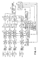
- FIG. l is a functional block diagram of signal processing apparatus in a phased array sector scanner.
- a plurality of transducer elements 10 transmit and receive ultrasonic waves, and the analog electrical signals generated by each of the transducer elements 10 are applied through preamplifiers 12, time gain control amplifiers 14 and translated to baseband frequencies with the baseband local oscillators 15 to analog to digital converters 16.
- the analog to digital converters 16 operate in response to a sampling clock 18 for sampling the amplified analog signals and generating digital data in response thereto.
- the sampling rate of the converters must equal at least twice the highest frequency in the amplified analog signals.
- the digital data from converters 16 are then stored in random access memories 20, and the data from memories 20 are later read, summed, and processed in an arithmetic logic unit 22 for generating video signal data at 24.
- a master controller 24 controls the operation of ALU 22, memory controller 26, AGC controller 28 and baseband local oscillator controller 17.
- FIG 2 is a block diagram of two analog to digital converters 16 for use in the apparatus of Figure l.
- the master clock signals for controlling operation of the A/D converters 16 are applied through programmable delay lines 30.
- the sampling of analog signals by the converter 16 can be skewed as required for a particular image focus.
- the clock frequency for the A/D converters is independent of the delay interposed by the delay lines 30. Accordingly, the time delay is not restricted by the sample rate of the A/D converters.
- FIG 3 is a functional block diagram of a digital random access memory 22 for use in the apparatus of Figure l.
- Digital data from an A/D converter 16 is applied at the input of memory 22, and data is read from memory 22 at the output.
- data for two vectors can be stored in the memory.
- the writing of data into the memory occurs during a phase l time period, and the reading of vector data from the memory occurs during phase 2 and phase 3 time periods.
- a write address 40 provides addresses through address multiplexer 42 to memory 22, and during the reading of data from memory 22 addresses are applied by read A address 44 and read B address 46 during phase 2 and phase 3, respectively.
- the addresses from 44 and 46 can be controlled in response to a desired focus stored at 48.
- the focus responds to a control signal on line 50 which is received by register 52.
- a desired focus from one vector can be achieved by selectively addressing the memory to read every address, every other address, or another selected sequence of addresses.
- the output from memory 22 is delayed by a HOLD OFF circuit 54 which controls the latches 56 and 58 for the A vector and B vector outputs, respectively. Accordingly, data read from memory 22 is delayed by the HOLD OFF circuit 54 to provide focusing, and data is read from the memory 22 under control of the focus unit 48 to provide focusing.
- Delay apparatus in accordance with the invention provides both a fine focus and course focus capability which is not restricted by the sampling rate of the analog to digital converters. While the invention has been described with reference to a specific embodiment, the description is illustrative of the invention and is not to be construed as limiting the invention.
Landscapes
- Engineering & Computer Science (AREA)
- Physics & Mathematics (AREA)
- General Physics & Mathematics (AREA)
- Computer Networks & Wireless Communication (AREA)
- Radar, Positioning & Navigation (AREA)
- Remote Sensing (AREA)
- Acoustics & Sound (AREA)
- Multimedia (AREA)
- Theoretical Computer Science (AREA)
- Ultra Sonic Daignosis Equipment (AREA)
- Investigating Or Analyzing Materials By The Use Of Ultrasonic Waves (AREA)
- Measurement Of Velocity Or Position Using Acoustic Or Ultrasonic Waves (AREA)
Claims (6)
- Procédé de focalisation de signaux dans un système d'imagerie à matrice en phase à ultrasons à bande de base, comprenant la séquence suivante des étapes consistant à :
Produire d'abord une multitude de signaux électriques analogiques en réponse à une onde ultrasonore reçue par une matrice d'éléments de transducteur, caractérisé par les étapes consistant a :
appliquer alors chaque signal analogique à un convertisseur analogique-numérique,
retarder alors sélectivement le fonctionnement de chaque convertisseur analogique-numérique, d'où le décalage dans le temps des sorties dudit convertisseur analogiquenumérique pour un foyer désiré, et
faire ensuite la sommation desdits signaux décalés dans le temps. - Procédé de focalisation de signaux dans un système d'imagerie à matrice en phase à ultrasons à bande de base, comprenant la séquence suivante des étapes consistant à :
produire d'abord une multitude de signaux électriques analogiques en réponse à une onde ultrasonore reçue par une matrice d'éléments de transducteur, caractérisé par les étapes consistant à :
appliquer alors chaque signal analogique à un convertisseur analogique-numérique,
retarder alors le fonctionnement de chaque convertisseur analogique-numérique pendant une première durée sélectionnée et ensuite échantillonner lesdits signaux analogiques à une fréquence d'échantillonnage,
stocker alors les données numériques échantillonnées sortant de chaque convertisseur analogique-numérique dans une mémoire numérique,
lire alors les données dans chaque mémoire numérique après une seconde durée sélectionnée qui suit le stockage desdites données dans ladite mémoire, et
procéder ensuite à la sommation des données provenant desdites mémoires numériques. - Procédé selon la revendication 2, dans lequel la première durée et la seconde durée sont variables afin de faire varier la focalisation des signaux.
- Dispositif pour la focalisation de signaux dans un système d'imagerie à matrice en phase à ultrasons, comprenant :
une matrice linéaire d'éléments de transducteur disposés de manière à produire une multitude de signaux électriques analogiques en réponse à une onde ultrasonique, caractérisé par :
une multitude de moyens de conversion analogiquenumérique, chacun connecté de manière à recevoir l'un desdits signaux analogiques et chacun produisant des données numériques, lesdits moyens de conversion comportant un moyen pour retarder sélectivement le fonctionnement desdits moyens de conversion pour le signal analogique sélectionné respectif, d'où le décalage dans le temps des signaux numériques,
un moyen de mémoire numérique monté de façon à recevoir et stocker lesdites données numériques et lire des données numériques stockées, ce moyen de mémoire numérique comportant un moyen pour retarder sélectivement la lecture desdites données numériques stockées, et
un moyen pour faire la somme des données numériques stockées lues dans ledit moyen de mémoire numérique. - Dispositif selon la revendication 4, dans lequel une mémoire numérique et un convertisseur analogique-numérique sont prévus pour chaque élément de transducteur.
- Dispositif selon la revendication 5, dans lequel chaque mémoire numérique a une capacité de stockage pour une multitude de vecteurs, d'où il résulte que les données pour une multitude de vecteurs peuvent être écrites séquentiellement et lues séquentiellement dans chaque mémoire.
Applications Claiming Priority (2)
| Application Number | Priority Date | Filing Date | Title |
|---|---|---|---|
| US06/794,095 US4669314A (en) | 1985-10-31 | 1985-10-31 | Variable focusing in ultrasound imaging using non-uniform sampling |
| US794095 | 1985-10-31 |
Publications (2)
| Publication Number | Publication Date |
|---|---|
| EP0224014A1 EP0224014A1 (fr) | 1987-06-03 |
| EP0224014B1 true EP0224014B1 (fr) | 1992-04-01 |
Family
ID=25161694
Family Applications (1)
| Application Number | Title | Priority Date | Filing Date |
|---|---|---|---|
| EP86114436A Expired - Lifetime EP0224014B1 (fr) | 1985-10-31 | 1986-10-17 | Focalisation variable pour imagerie à ultrasons au moyen d'un échantillonnage non-uniforme |
Country Status (6)
| Country | Link |
|---|---|
| US (1) | US4669314A (fr) |
| EP (1) | EP0224014B1 (fr) |
| JP (1) | JPS62116279A (fr) |
| KR (1) | KR870004387A (fr) |
| DE (1) | DE3684669D1 (fr) |
| IL (1) | IL79845A0 (fr) |
Families Citing this family (29)
| Publication number | Priority date | Publication date | Assignee | Title |
|---|---|---|---|---|
| US4815047A (en) * | 1986-06-20 | 1989-03-21 | Hewlett-Packard Company | Synthetic focus annular array transducer |
| US4839652A (en) * | 1987-06-01 | 1989-06-13 | General Electric Company | Method and apparatus for high speed digital phased array coherent imaging system |
| US5005419A (en) * | 1988-06-16 | 1991-04-09 | General Electric Company | Method and apparatus for coherent imaging system |
| US4974211A (en) * | 1989-03-17 | 1990-11-27 | Hewlett-Packard Company | Digital ultrasound system with dynamic focus |
| US4983970A (en) * | 1990-03-28 | 1991-01-08 | General Electric Company | Method and apparatus for digital phased array imaging |
| US5113706A (en) * | 1990-07-03 | 1992-05-19 | Hewlett-Packard Company | Ultrasound system with dynamic transmit focus |
| US5111695A (en) * | 1990-07-11 | 1992-05-12 | General Electric Company | Dynamic phase focus for coherent imaging beam formation |
| US5121364A (en) * | 1991-08-07 | 1992-06-09 | General Electric Company | Time frequency control filter for an ultrasonic imaging system |
| US5142649A (en) * | 1991-08-07 | 1992-08-25 | General Electric Company | Ultrasonic imaging system with multiple, dynamically focused transmit beams |
| US5235982A (en) * | 1991-09-30 | 1993-08-17 | General Electric Company | Dynamic transmit focusing of a steered ultrasonic beam |
| US5291892A (en) * | 1991-11-04 | 1994-03-08 | General Electric Company | Ultrasonic flow imaging |
| US5172343A (en) * | 1991-12-06 | 1992-12-15 | General Electric Company | Aberration correction using beam data from a phased array ultrasonic scanner |
| GB9126944D0 (en) * | 1991-12-19 | 1992-02-19 | Secr Defence | A digital beamforming array |
| US5230340A (en) * | 1992-04-13 | 1993-07-27 | General Electric Company | Ultrasound imaging system with improved dynamic focusing |
| US5685308A (en) * | 1994-08-05 | 1997-11-11 | Acuson Corporation | Method and apparatus for receive beamformer system |
| US5928152A (en) * | 1994-08-05 | 1999-07-27 | Acuson Corporation | Method and apparatus for a baseband processor of a receive beamformer system |
| US6029116A (en) * | 1994-08-05 | 2000-02-22 | Acuson Corporation | Method and apparatus for a baseband processor of a receive beamformer system |
| US5793701A (en) * | 1995-04-07 | 1998-08-11 | Acuson Corporation | Method and apparatus for coherent image formation |
| US5991239A (en) * | 1996-05-08 | 1999-11-23 | Mayo Foundation For Medical Education And Research | Confocal acoustic force generator |
| US5740805A (en) * | 1996-11-19 | 1998-04-21 | Analogic Corporation | Ultrasound beam softening compensation system |
| US5844139A (en) * | 1996-12-30 | 1998-12-01 | General Electric Company | Method and apparatus for providing dynamically variable time delays for ultrasound beamformer |
| US20020110187A1 (en) * | 2001-02-13 | 2002-08-15 | Sigmatel, Inc. | Method and apparatus for providing domain conversions for multiple channels and applications thereof |
| KR100419806B1 (ko) * | 2001-12-31 | 2004-02-21 | 주식회사 메디슨 | 평면파를 이용하는 초음파 영상의 합성 구경 집속 방법 |
| US7936338B2 (en) | 2002-10-01 | 2011-05-03 | Sony Corporation | Display unit and its manufacturing method |
| KR100748585B1 (ko) * | 2005-07-15 | 2007-08-13 | 주식회사 메디슨 | 부가정보를 이용하여 영상을 구성하는 초음파 시스템 |
| KR101242368B1 (ko) * | 2012-04-23 | 2013-03-15 | 주식회사 힐세리온 | 2차원 배열 데이터를 이용한 모바일 초음파 진단 프로브 장치 및 이를 이용한 모바일 초음파 진단 시스템 |
| US10613205B2 (en) | 2014-10-06 | 2020-04-07 | Analog Devices, Inc. | Systems and methods for ultrasound beamforming |
| JP6779886B2 (ja) | 2015-01-23 | 2020-11-04 | ダルハウジー ユニバーシティー | 可変サンプリングを用いたビームフォーミングのためのシステム及び方法 |
| US20200405266A1 (en) * | 2019-06-25 | 2020-12-31 | Butterfly Network, Inc. | Methods and apparatuses for processing ultrasound signals |
Citations (3)
| Publication number | Priority date | Publication date | Assignee | Title |
|---|---|---|---|---|
| US4155259A (en) * | 1978-05-24 | 1979-05-22 | General Electric Company | Ultrasonic imaging system |
| JPS576377A (en) * | 1980-06-13 | 1982-01-13 | Hitachi Ltd | Multiplication array type ultrasonic wave searching device |
| US4325257A (en) * | 1980-02-20 | 1982-04-20 | Kino Gordon S | Real-time digital, synthetic-focus, acoustic imaging system |
Family Cites Families (14)
| Publication number | Priority date | Publication date | Assignee | Title |
|---|---|---|---|---|
| US4105018A (en) * | 1976-02-02 | 1978-08-08 | University Of Utah | Acoustic examination, material characterization and imaging of the internal structure of a body by measurement of the time-of-flight of acoustic energy therethrough |
| US4152678A (en) * | 1976-07-01 | 1979-05-01 | Board of Trustees of the Leland Stanford Jr. Unv. | Cascade charge coupled delay line device for compound delays |
| GB1592601A (en) * | 1977-02-19 | 1981-07-08 | Rolls Royce | Apparatus for ultrasonic examination |
| US4227417A (en) * | 1977-06-13 | 1980-10-14 | New York Institute Of Technology | Dynamic focusing apparatus and method |
| US4173007A (en) * | 1977-07-01 | 1979-10-30 | G. D. Searle & Co. | Dynamically variable electronic delay lines for real time ultrasonic imaging systems |
| JPS5468090A (en) * | 1977-11-10 | 1979-05-31 | Tokyo Shibaura Electric Co | Ultrasonic scanner |
| US4155258A (en) * | 1978-05-24 | 1979-05-22 | General Electric Company | Ultrasonic imaging system |
| US4154113A (en) * | 1978-05-24 | 1979-05-15 | General Electric Company | Ultrasonic imaging system |
| US4155260A (en) * | 1978-05-24 | 1979-05-22 | General Electric Company | Ultrasonic imaging system |
| US4165537A (en) * | 1978-08-16 | 1979-08-21 | General Electric Company | Analog charge transfer apparatus |
| US4290310A (en) * | 1979-07-09 | 1981-09-22 | Varian Associates, Inc. | Ultrasonic imaging system using digital control |
| US4290127A (en) * | 1979-12-03 | 1981-09-15 | Raytheon Company | Beamformer with reduced sampling rate |
| JPS6060061B2 (ja) * | 1980-10-27 | 1985-12-27 | 株式会社東芝 | 画像処理システム |
| JPS58113746A (ja) * | 1981-12-26 | 1983-07-06 | Toshiba Corp | 電子走査型超音波探傷装置 |
-
1985
- 1985-10-31 US US06/794,095 patent/US4669314A/en not_active Expired - Lifetime
-
1986
- 1986-08-26 IL IL79845A patent/IL79845A0/xx unknown
- 1986-10-17 DE DE8686114436T patent/DE3684669D1/de not_active Expired - Lifetime
- 1986-10-17 EP EP86114436A patent/EP0224014B1/fr not_active Expired - Lifetime
- 1986-10-28 JP JP61254854A patent/JPS62116279A/ja active Pending
- 1986-10-30 KR KR860009119A patent/KR870004387A/ko active Pending
Patent Citations (3)
| Publication number | Priority date | Publication date | Assignee | Title |
|---|---|---|---|---|
| US4155259A (en) * | 1978-05-24 | 1979-05-22 | General Electric Company | Ultrasonic imaging system |
| US4325257A (en) * | 1980-02-20 | 1982-04-20 | Kino Gordon S | Real-time digital, synthetic-focus, acoustic imaging system |
| JPS576377A (en) * | 1980-06-13 | 1982-01-13 | Hitachi Ltd | Multiplication array type ultrasonic wave searching device |
Also Published As
| Publication number | Publication date |
|---|---|
| IL79845A0 (en) | 1986-11-30 |
| US4669314A (en) | 1987-06-02 |
| DE3684669D1 (de) | 1992-05-07 |
| JPS62116279A (ja) | 1987-05-27 |
| KR870004387A (ko) | 1987-05-09 |
| EP0224014A1 (fr) | 1987-06-03 |
Similar Documents
| Publication | Publication Date | Title |
|---|---|---|
| US4669314A (en) | Variable focusing in ultrasound imaging using non-uniform sampling | |
| CA1141855A (fr) | Systeme de visualisation ultrasonore a commande digitale | |
| US5544128A (en) | Multi-beam digital beamforming method and apparatus | |
| US6126602A (en) | Phased array acoustic systems with intra-group processors | |
| US5522391A (en) | Delay generator for phased array ultrasound beamformer | |
| US6514205B1 (en) | Medical digital ultrasonic imaging apparatus capable of storing and reusing radio-frequency (RF) ultrasound pulse echoes | |
| US5844139A (en) | Method and apparatus for providing dynamically variable time delays for ultrasound beamformer | |
| US5469851A (en) | Time multiplexed digital ultrasound beamformer | |
| US4839652A (en) | Method and apparatus for high speed digital phased array coherent imaging system | |
| JP3100637B2 (ja) | 多重位相並列処理を持つディジタルビームフォーマ | |
| JP2776986B2 (ja) | 部分的なビーム形成 | |
| US5419330A (en) | Ultrasonic diagnostic equipment | |
| JPS62280650A (ja) | 超音波信号の遅延方法および装置 | |
| JP2770391B2 (ja) | 超音波撮像装置 | |
| US4484477A (en) | Variable delay memory system | |
| US5088496A (en) | Ultrasonic echography apparatus utilizing a digital device for forming channels, in the receiving mode | |
| US5591911A (en) | Ultrasound signal processor | |
| Feldkamper et al. | Low power delay calculation for digital beamforming in handheld ultrasound systems | |
| US7993270B2 (en) | Digital receive-focusing apparatus using analogue multiplexers | |
| EP0959368B1 (fr) | Technique d'échantillonage de bande pour focalisation totale dans les systèmes d'imagerie à groupement de transducteurs | |
| EP0702247B1 (fr) | Méthode et appareil pour visualisation ultrasonique | |
| JP2722910B2 (ja) | 超音波診断装置 | |
| EP0543595A1 (fr) | Formateur de faisceau pour appareil de diagnostic et ultrasons | |
| JPH0819537A (ja) | 超音波装置の受波整相回路 | |
| JPH04161878A (ja) | 可変遅延回路 |
Legal Events
| Date | Code | Title | Description |
|---|---|---|---|
| PUAI | Public reference made under article 153(3) epc to a published international application that has entered the european phase |
Free format text: ORIGINAL CODE: 0009012 |
|
| AK | Designated contracting states |
Kind code of ref document: A1 Designated state(s): DE FR GB NL |
|
| 17P | Request for examination filed |
Effective date: 19871111 |
|
| 17Q | First examination report despatched |
Effective date: 19890818 |
|
| GRAA | (expected) grant |
Free format text: ORIGINAL CODE: 0009210 |
|
| AK | Designated contracting states |
Kind code of ref document: B1 Designated state(s): DE FR GB NL |
|
| ET | Fr: translation filed | ||
| REF | Corresponds to: |
Ref document number: 3684669 Country of ref document: DE Date of ref document: 19920507 |
|
| PGFP | Annual fee paid to national office [announced via postgrant information from national office to epo] |
Ref country code: FR Payment date: 19920913 Year of fee payment: 7 |
|
| PGFP | Annual fee paid to national office [announced via postgrant information from national office to epo] |
Ref country code: GB Payment date: 19920922 Year of fee payment: 7 |
|
| REG | Reference to a national code |
Ref country code: GB Ref legal event code: 746 |
|
| PGFP | Annual fee paid to national office [announced via postgrant information from national office to epo] |
Ref country code: NL Payment date: 19921031 Year of fee payment: 7 |
|
| PLBE | No opposition filed within time limit |
Free format text: ORIGINAL CODE: 0009261 |
|
| STAA | Information on the status of an ep patent application or granted ep patent |
Free format text: STATUS: NO OPPOSITION FILED WITHIN TIME LIMIT |
|
| REG | Reference to a national code |
Ref country code: FR Ref legal event code: DL |
|
| 26N | No opposition filed | ||
| PG25 | Lapsed in a contracting state [announced via postgrant information from national office to epo] |
Ref country code: GB Effective date: 19931017 |
|
| PG25 | Lapsed in a contracting state [announced via postgrant information from national office to epo] |
Ref country code: NL Effective date: 19940501 |
|
| GBPC | Gb: european patent ceased through non-payment of renewal fee |
Effective date: 19931017 |
|
| NLV4 | Nl: lapsed or anulled due to non-payment of the annual fee | ||
| PG25 | Lapsed in a contracting state [announced via postgrant information from national office to epo] |
Ref country code: FR Effective date: 19940630 |
|
| REG | Reference to a national code |
Ref country code: FR Ref legal event code: ST |
|
| PGFP | Annual fee paid to national office [announced via postgrant information from national office to epo] |
Ref country code: DE Payment date: 19950925 Year of fee payment: 10 |
|
| PG25 | Lapsed in a contracting state [announced via postgrant information from national office to epo] |
Ref country code: DE Effective date: 19970701 |