EP0224203A2 - Control apparatus of speed, position and specific functions for industrial sewing machines - Google Patents
Control apparatus of speed, position and specific functions for industrial sewing machines Download PDFInfo
- Publication number
- EP0224203A2 EP0224203A2 EP86116103A EP86116103A EP0224203A2 EP 0224203 A2 EP0224203 A2 EP 0224203A2 EP 86116103 A EP86116103 A EP 86116103A EP 86116103 A EP86116103 A EP 86116103A EP 0224203 A2 EP0224203 A2 EP 0224203A2
- Authority
- EP
- European Patent Office
- Prior art keywords
- fact
- spool
- machine
- speed
- shaft
- Prior art date
- Legal status (The legal status is an assumption and is not a legal conclusion. Google has not performed a legal analysis and makes no representation as to the accuracy of the status listed.)
- Granted
Links
- 238000009958 sewing Methods 0.000 title claims abstract description 18
- 238000000034 method Methods 0.000 claims abstract description 9
- 230000006698 induction Effects 0.000 description 2
- 230000002045 lasting effect Effects 0.000 description 2
- 229910000831 Steel Inorganic materials 0.000 description 1
- 230000004913 activation Effects 0.000 description 1
- XAGFODPZIPBFFR-UHFFFAOYSA-N aluminium Chemical compound [Al] XAGFODPZIPBFFR-UHFFFAOYSA-N 0.000 description 1
- 229910052782 aluminium Inorganic materials 0.000 description 1
- 239000004411 aluminium Substances 0.000 description 1
- 238000010276 construction Methods 0.000 description 1
- 238000010586 diagram Methods 0.000 description 1
- 239000000428 dust Substances 0.000 description 1
- 230000000694 effects Effects 0.000 description 1
- 239000000463 material Substances 0.000 description 1
- 230000003287 optical effect Effects 0.000 description 1
- 210000000056 organ Anatomy 0.000 description 1
- 239000010959 steel Substances 0.000 description 1
- 230000026683 transduction Effects 0.000 description 1
- 238000010361 transduction Methods 0.000 description 1
- 238000011144 upstream manufacturing Methods 0.000 description 1
Images

Classifications
-
- D—TEXTILES; PAPER
- D05—SEWING; EMBROIDERING; TUFTING
- D05B—SEWING
- D05B69/00—Driving-gear; Control devices
- D05B69/14—Devices for changing speed or for reversing direction of rotation
- D05B69/18—Devices for changing speed or for reversing direction of rotation electric, e.g. foot pedals
Definitions
- the present invention relates to control apparatus of speed, position and specific functions for industrial sewing machines.
- the present invention refers to control apparatus of speed, position and special functions for industrial sewing machines, realized with a digital technique having an input with variable inductance.
- the various tracks incised on the photographic cams acting as so many optic switches, transmit the various signals to the machine for the speed, position of the needle, pressure foot, threadcutter, etc.
- the brake-clutch unit which is the principal organ, is controlled with the same technique according to the characteristics of each embodiment, for which a tiresome adjustment and line-up of several parts is required.
- the present invention solves the above-mentioned problems and drawbacks by conducting a control on speed, position and specific functions in industrial sewing machines, through a digital technique with an input having variable inductance.
- the control apparatus of the present invention mainly consists of a spool intersected by a shaft, activated by a lever connected to the sewing machine treadle by means of a system of rods and levers.
- Said inductance outputs are transmitted to the electrovalves, dedicated to various service operations, such as stopping of the machine, activation of a threadcutter or the pressure treadle, reverse gear or positioning of the needle, etc. through :
- the power actuator sets into motion the various electrovalves dedicated to the various working stages.
- the advantages obtained from the present invention consist mainly in the fact that since the input does not necessitate specific optic or contact switches and employs only differentiated impulses or signals generated from the linear variation of inductance of a spool intersected by a rod, it gives a high electrical reliability due to an almost total absence of mechanical wear.
- the synchronizer being provided with a single standard disk, may be applied to a great number of sewing machine types or makes, even with construction characteristics different one from the other and permits, moreover, thanks to the digital technique adopted herein, extremely accurate and lasting controls and adjustments.
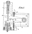
- the input with variable inductance 7 comprises a spool 1 intersected by a shaft 2; a lever 3, activated by a machine treadle, and which moves said shaft 2 inside the spool 1; a return spring 4 which keeps the lever 3 in the lower downstroke position and an adjustable screw 5 which sets the stroke of the lever 3.
- the position and speed transducer unit comprising a spool 1 containing a sliding rod 2 is housed in a casing made of sheet steel or cast aluminium or other material suitable for the purpose.
- the lever 3 is activated by the treadle through a system of rods not shown in the figure.
- the varying controlled pressure exerted by the operator on the treadle, forming part of the unit 7 comprises an angular shifting of the lever 3 which then acts on the shaft 2 sliding in the spool 1, causing variations in continuous inductance inside the same, corresponding to each position that the shaft 2 moves into.
- the computer 8 Once the latter has received the various signals from the computer 8, it activates the separate electrovalves which control the various service operations, such as the treadle lifter, the reverse gear, return of the flywheel and the threadcutter.
- the display 9 placed so as to be under the operator's immediate control, permits a continuous check, in the form of numbers, on the sewing machine camshaft positions.
- the initial setting of the technical panel 10 is carried out just once at the beginning and subsequently memorized by the computer. This operation is facilitated by appropriate symbols or reference points present on the same panel 10. This permits setting of the starting point for all subsequent adjustments, regardless of the type of machine being used.
- Use of the computer and digital technique make it possible to set one or more positions of the machine camshaft and memorization of same ; moreover, it is used to drive the brake-postion group by means of a regulator 14 and sets accurately the maximum machine speed, which consequently cannot be exceeded.
Landscapes
- Engineering & Computer Science (AREA)
- Mechanical Engineering (AREA)
- Textile Engineering (AREA)
- Sewing Machines And Sewing (AREA)
- Control Of Electric Motors In General (AREA)
Abstract
Description
- The present invention relates to control apparatus of speed, position and specific functions for industrial sewing machines.
- To be more precise, the present invention refers to control apparatus of speed, position and special functions for industrial sewing machines, realized with a digital technique having an input with variable inductance.
- Functions control apparatus for industrial sewing machines are already known ; however, in the former, the input (i.e. the transduction of the controlled pressure exerted by the operator on the machine treadle) is determined by means of disks or rotating photographic cams.
- The various tracks incised on the photographic cams, acting as so many optic switches, transmit the various signals to the machine for the speed, position of the needle, pressure foot, threadcutter, etc.
- Other apparatus achieves the same effect not through an optical effect, but by means of simple contacts, others adopt potentiometers. In all these cases working set- backs occur quite frequently, caused by wear of the contacts, exposure to dust, as well as a limited mechanical endurance of the parts.
- Moreover, in these instruments the brake-clutch unit, which is the principal organ, is controlled with the same technique according to the characteristics of each embodiment, for which a tiresome adjustment and line-up of several parts is required.
- Another drawback found in the known apparatus is that the type of synchronizers found in them, comprising disks or optic switches, or other contact systems, cannot be interchanged, that is to say, they may not be adopted indiscriminately for sewing machines, the characteristics of which differ from one to the other : consequently, it is necessary that each type and/or make of machine be matched with specific cams or contact systems. Finally, the initial line-up in the known instruments involves a a great deal of time and does not reach the necessary, lasting precision and the control of maximum speed.
- The present invention solves the above-mentioned problems and drawbacks by conducting a control on speed, position and specific functions in industrial sewing machines, through a digital technique with an input having variable inductance.
- The control apparatus of the present invention mainly consists of a spool intersected by a shaft, activated by a lever connected to the sewing machine treadle by means of a system of rods and levers.
- The various positions that the shaft or rod, sliding in the spool and activated by the lever, moves to, as a result of the controlled pressure exerted by the operator on the treadle, determine the same number of outputs with differentiated inductance. Said inductance outputs are transmitted to the electrovalves, dedicated to various service operations, such as stopping of the machine, activation of a threadcutter or the pressure treadle, reverse gear or positioning of the needle, etc. through :
- an electronic computer with numerical display, for the processing of impulses deriving from the spool itself;
- a technical panel and synchronizer forming an integral part of the main camshaft of the sewing machine;
- The power actuator sets into motion the various electrovalves dedicated to the various working stages.
- The advantages obtained from the present invention consist mainly in the fact that since the input does not necessitate specific optic or contact switches and employs only differentiated impulses or signals generated from the linear variation of inductance of a spool intersected by a rod, it gives a high electrical reliability due to an almost total absence of mechanical wear.
- Moreover, the synchronizer, being provided with a single standard disk, may be applied to a great number of sewing machine types or makes, even with construction characteristics different one from the other and permits, moreover, thanks to the digital technique adopted herein, extremely accurate and lasting controls and adjustments. The present invention will be better understood from the following detailed description in which reference is made to the appended drawings which show a preferred embodiment, illustrative but not limitative of the control equipment of the present invention, wherein :
- figure 1 shows a perspective schematic view of the driving device of the spool shaft; and
- figure 2 shows the connection diagram of the parts comprising the control equipment of the present invention. With reference to figure 2, the control apparatus of speed, position and specific functions for sewing machines realized using a digital technique, with variable induction input comprises an input having variable induction 7, a
computer 8 with display 9, atechnical panel 10,operator panel 11, an electrovalve power actuator 12, a brake-clutch group regulator 14 placed upstream of the brake-clutch group 13 and themotor 15, and asynchronizer 16. - As shown in figure 1, and according to the present invention, the input with variable inductance 7 comprises a
spool 1 intersected by ashaft 2; alever 3, activated by a machine treadle, and which moves saidshaft 2 inside thespool 1; areturn spring 4 which keeps thelever 3 in the lower downstroke position and anadjustable screw 5 which sets the stroke of thelever 3. - The
screw 5 is blocked by a lock nut 6. In accordance with the present invention, the position and speed transducer unit, comprising aspool 1 containing asliding rod 2, is housed in a casing made of sheet steel or cast aluminium or other material suitable for the purpose. Thelever 3 is activated by the treadle through a system of rods not shown in the figure. The varying controlled pressure exerted by the operator on the treadle, forming part of the unit 7 comprises an angular shifting of thelever 3 which then acts on theshaft 2 sliding in thespool 1, causing variations in continuous inductance inside the same, corresponding to each position that theshaft 2 moves into. - The
spool 1, linked to acomputer 8, preferably placed near a working table but in such a manner as not to impede sewing operations, transmits to same the differentiated impulses, caused by theshaft 2 sliding in thespool 1. Said impulses, transduced in numeral entities, are assimilated by thecomputer 8 which, depending on the inputs, establishes the appropriate signals to be sent to an electrovalve power actuator 12. Once the latter has received the various signals from thecomputer 8, it activates the separate electrovalves which control the various service operations, such as the treadle lifter, the reverse gear, return of the flywheel and the threadcutter. - The display 9, placed so as to be under the operator's immediate control, permits a continuous check, in the form of numbers, on the sewing machine camshaft positions.
- The initial setting of the
technical panel 10 is carried out just once at the beginning and subsequently memorized by the computer. This operation is facilitated by appropriate symbols or reference points present on thesame panel 10. This permits setting of the starting point for all subsequent adjustments, regardless of the type of machine being used. Use of the computer and digital technique make it possible to set one or more positions of the machine camshaft and memorization of same ; moreover, it is used to drive the brake-postion group by means of aregulator 14 and sets accurately the maximum machine speed, which consequently cannot be exceeded. During sewing operations, it may be necessary to stop the needle or the treadle in the high or low position for both at the same time, or first for one and then the other, together with other operations such as cutting the thread ; all these operations, previously scheduled and memorized by thecomputer 8, may be recalled, whenever necessary, according to an infinity of combinations, through theoperator panel 11, equipped with a keyboard bearing symbols and connected to thecomputer 8.
and an electrovalve power actuator.
Claims (6)
Priority Applications (1)
| Application Number | Priority Date | Filing Date | Title |
|---|---|---|---|
| AT86116103T ATE67534T1 (en) | 1985-11-26 | 1986-11-20 | FOOT LEVER FOR SEWING MACHINE. |
Applications Claiming Priority (2)
| Application Number | Priority Date | Filing Date | Title |
|---|---|---|---|
| IT22993/85A IT1186398B (en) | 1985-11-26 | 1985-11-26 | SPEED, POSITION AND SPECIFIC FUNCTION CONTROL EQUIPMENT FOR INDUSTRIAL SEWING MACHINES, RELATED IN DIGITAL TECHNIQUE WITH INDUCTANCE VARIATION "INPUT" |
| IT2299385 | 1985-11-26 |
Publications (3)
| Publication Number | Publication Date |
|---|---|
| EP0224203A2 true EP0224203A2 (en) | 1987-06-03 |
| EP0224203A3 EP0224203A3 (en) | 1988-02-10 |
| EP0224203B1 EP0224203B1 (en) | 1991-09-18 |
Family
ID=11202657
Family Applications (1)
| Application Number | Title | Priority Date | Filing Date |
|---|---|---|---|
| EP86116103A Expired EP0224203B1 (en) | 1985-11-26 | 1986-11-20 | Control apparatus of speed, position and specific functions for industrial sewing machines |
Country Status (5)
| Country | Link |
|---|---|
| EP (1) | EP0224203B1 (en) |
| AT (1) | ATE67534T1 (en) |
| DE (1) | DE3681563D1 (en) |
| ES (1) | ES2021564T3 (en) |
| IT (1) | IT1186398B (en) |
Cited By (1)
| Publication number | Priority date | Publication date | Assignee | Title |
|---|---|---|---|---|
| EP0505660A1 (en) * | 1991-03-27 | 1992-09-30 | COMELZ S.p.A. | Control unit for an electric drive motor of industrial processing machinery. |
Family Cites Families (2)
| Publication number | Priority date | Publication date | Assignee | Title |
|---|---|---|---|---|
| JPS57208881A (en) * | 1981-06-15 | 1982-12-22 | Matsushita Electric Ind Co Ltd | Driving system for sewing machine |
| RO82939A2 (en) * | 1983-01-24 | 1985-10-31 | Institutul De Cercetare Stiintifica Si Inginerie Tehnologica Pentru Industria Electrotehnica,Ro | ELECTRONIC CONTROL INSTALLATION OF CONTROL SYSTEMS FOR ACTUATION SYSTEMS WITH ELECTROMAGNETIC COUPLINGS FOR SEWING AND / OR FASTENING MACHINES |
-
1985
- 1985-11-26 IT IT22993/85A patent/IT1186398B/en active
-
1986
- 1986-11-20 EP EP86116103A patent/EP0224203B1/en not_active Expired
- 1986-11-20 DE DE8686116103T patent/DE3681563D1/en not_active Expired - Fee Related
- 1986-11-20 ES ES198686116103T patent/ES2021564T3/en not_active Expired - Lifetime
- 1986-11-20 AT AT86116103T patent/ATE67534T1/en not_active IP Right Cessation
Cited By (2)
| Publication number | Priority date | Publication date | Assignee | Title |
|---|---|---|---|---|
| EP0505660A1 (en) * | 1991-03-27 | 1992-09-30 | COMELZ S.p.A. | Control unit for an electric drive motor of industrial processing machinery. |
| US5336981A (en) * | 1991-03-27 | 1994-08-09 | Comelz S.P.A. | Control unit for an electric drive motor of industrial processing machinery |
Also Published As
| Publication number | Publication date |
|---|---|
| ES2021564A4 (en) | 1991-11-16 |
| ES2021564T3 (en) | 1992-04-01 |
| IT1186398B (en) | 1987-11-26 |
| IT8522993A0 (en) | 1985-11-26 |
| ATE67534T1 (en) | 1991-10-15 |
| EP0224203A3 (en) | 1988-02-10 |
| DE3681563D1 (en) | 1991-10-24 |
| EP0224203B1 (en) | 1991-09-18 |
Similar Documents
| Publication | Publication Date | Title |
|---|---|---|
| JP2004522154A (en) | Microtome | |
| DE42268T1 (en) | DENTAL APPARATUS WITH A NUMBER OF DENTAL INSTRUMENTS CONNECTED TO A COMMON CONTROL CIRCUIT AND TO A COMMON SWITCHING UNIT. | |
| US3877405A (en) | Automatically adjustable apparatus for embroidery stitching | |
| US4674928A (en) | Milling machine controller | |
| US3162232A (en) | Multiple depth control for power press brakes | |
| US3134325A (en) | Ink adjusting mechanism | |
| EP0224203A2 (en) | Control apparatus of speed, position and specific functions for industrial sewing machines | |
| GB2069769A (en) | Positioning drive | |
| US4167912A (en) | Sewing machine stitch length override and feed balance for digital feed actuators | |
| JPS59116459A (en) | Tension regulator of flat traverse knitting machine | |
| US2805552A (en) | Pre-selector dial devices | |
| US1383438A (en) | Sewing-machine | |
| US2487031A (en) | Automatic back gauge spacer | |
| DE3519849C1 (en) | Blindstitch sewing machine | |
| US3015350A (en) | Bacon slicer having adjustable control of group size | |
| US3026834A (en) | Automatic tool control mechanisms | |
| US3611352A (en) | Device for automatically, or semiautomatically, changing the length of stroke of the grating advance mechanism in welding machines for welding wire gratings | |
| EP0749813A1 (en) | Food product slicers | |
| GB2070419A (en) | Slicing machines | |
| US2105288A (en) | Spindle driving transmission | |
| FR2511107B1 (en) | ||
| EP0074250A2 (en) | Press speed control and indication system | |
| US3191412A (en) | Press brake control | |
| US3510610A (en) | Switching apparatus | |
| US5117367A (en) | Cutting machine |
Legal Events
| Date | Code | Title | Description |
|---|---|---|---|
| PUAI | Public reference made under article 153(3) epc to a published international application that has entered the european phase |
Free format text: ORIGINAL CODE: 0009012 |
|
| AK | Designated contracting states |
Kind code of ref document: A2 Designated state(s): AT BE CH DE ES FR GB GR LI LU NL SE |
|
| PUAL | Search report despatched |
Free format text: ORIGINAL CODE: 0009013 |
|
| AK | Designated contracting states |
Kind code of ref document: A3 Designated state(s): AT BE CH DE ES FR GB GR LI LU NL SE |
|
| 17P | Request for examination filed |
Effective date: 19880507 |
|
| 17Q | First examination report despatched |
Effective date: 19891018 |
|
| GRAA | (expected) grant |
Free format text: ORIGINAL CODE: 0009210 |
|
| AK | Designated contracting states |
Kind code of ref document: B1 Designated state(s): AT BE CH DE ES FR GB GR LI LU NL SE |
|
| PG25 | Lapsed in a contracting state [announced via postgrant information from national office to epo] |
Ref country code: SE Effective date: 19910918 Ref country code: NL Effective date: 19910918 Ref country code: LI Effective date: 19910918 Ref country code: GR Free format text: LAPSE BECAUSE OF FAILURE TO SUBMIT A TRANSLATION OF THE DESCRIPTION OR TO PAY THE FEE WITHIN THE PRESCRIBED TIME-LIMIT Effective date: 19910918 Ref country code: CH Effective date: 19910918 Ref country code: AT Effective date: 19910918 |
|
| REF | Corresponds to: |
Ref document number: 67534 Country of ref document: AT Date of ref document: 19911015 Kind code of ref document: T |
|
| REF | Corresponds to: |
Ref document number: 3681563 Country of ref document: DE Date of ref document: 19911024 |
|
| ET | Fr: translation filed | ||
| PG25 | Lapsed in a contracting state [announced via postgrant information from national office to epo] |
Ref country code: LU Free format text: LAPSE BECAUSE OF NON-PAYMENT OF DUE FEES Effective date: 19911130 |
|
| REG | Reference to a national code |
Ref country code: CH Ref legal event code: PL |
|
| NLV1 | Nl: lapsed or annulled due to failure to fulfill the requirements of art. 29p and 29m of the patents act | ||
| REG | Reference to a national code |
Ref country code: ES Ref legal event code: FG2A Ref document number: 2021564 Country of ref document: ES Kind code of ref document: T3 |
|
| PLBE | No opposition filed within time limit |
Free format text: ORIGINAL CODE: 0009261 |
|
| STAA | Information on the status of an ep patent application or granted ep patent |
Free format text: STATUS: NO OPPOSITION FILED WITHIN TIME LIMIT |
|
| 26N | No opposition filed | ||
| PGFP | Annual fee paid to national office [announced via postgrant information from national office to epo] |
Ref country code: GB Payment date: 19941121 Year of fee payment: 9 Ref country code: BE Payment date: 19941121 Year of fee payment: 9 |
|
| PGFP | Annual fee paid to national office [announced via postgrant information from national office to epo] |
Ref country code: ES Payment date: 19941122 Year of fee payment: 9 |
|
| PGFP | Annual fee paid to national office [announced via postgrant information from national office to epo] |
Ref country code: FR Payment date: 19941124 Year of fee payment: 9 |
|
| PGFP | Annual fee paid to national office [announced via postgrant information from national office to epo] |
Ref country code: DE Payment date: 19950124 Year of fee payment: 9 |
|
| PG25 | Lapsed in a contracting state [announced via postgrant information from national office to epo] |
Ref country code: GB Effective date: 19951120 |
|
| PG25 | Lapsed in a contracting state [announced via postgrant information from national office to epo] |
Ref country code: ES Free format text: LAPSE BECAUSE OF NON-PAYMENT OF DUE FEES Effective date: 19951121 |
|
| PG25 | Lapsed in a contracting state [announced via postgrant information from national office to epo] |
Ref country code: BE Effective date: 19951130 |
|
| BERE | Be: lapsed |
Owner name: ELEMAC S.P.A. Effective date: 19951130 |
|
| GBPC | Gb: european patent ceased through non-payment of renewal fee |
Effective date: 19951120 |
|
| PG25 | Lapsed in a contracting state [announced via postgrant information from national office to epo] |
Ref country code: FR Effective date: 19960731 |
|
| PG25 | Lapsed in a contracting state [announced via postgrant information from national office to epo] |
Ref country code: DE Effective date: 19960801 |
|
| REG | Reference to a national code |
Ref country code: FR Ref legal event code: ST |
|
| REG | Reference to a national code |
Ref country code: ES Ref legal event code: FD2A Effective date: 19961213 |