EP0224295A1 - Dispositif de transport d'une pile de feuilles - Google Patents
Dispositif de transport d'une pile de feuilles Download PDFInfo
- Publication number
- EP0224295A1 EP0224295A1 EP86201952A EP86201952A EP0224295A1 EP 0224295 A1 EP0224295 A1 EP 0224295A1 EP 86201952 A EP86201952 A EP 86201952A EP 86201952 A EP86201952 A EP 86201952A EP 0224295 A1 EP0224295 A1 EP 0224295A1
- Authority
- EP
- European Patent Office
- Prior art keywords
- pair
- bundle
- conveyor means
- arm
- rollers
- Prior art date
- Legal status (The legal status is an assumption and is not a legal conclusion. Google has not performed a legal analysis and makes no representation as to the accuracy of the status listed.)
- Granted
Links
- 230000000717 retained effect Effects 0.000 claims description 5
- 229940102098 revolution Drugs 0.000 claims description 2
- 230000000694 effects Effects 0.000 description 3
- 230000002411 adverse Effects 0.000 description 2
- 238000007599 discharging Methods 0.000 description 1
Images


Classifications
-
- B—PERFORMING OPERATIONS; TRANSPORTING
- B65—CONVEYING; PACKING; STORING; HANDLING THIN OR FILAMENTARY MATERIAL
- B65H—HANDLING THIN OR FILAMENTARY MATERIAL, e.g. SHEETS, WEBS, CABLES
- B65H31/00—Pile receivers
- B65H31/30—Arrangements for removing completed piles
- B65H31/3027—Arrangements for removing completed piles by the nip between moving belts or rollers
Definitions
- This invention relates to a device for conveying a bundle of sheets, comprising at least one first drivable pair of conveyor means which can together form a nip for the conveyance of the bundle and at least one second drivable pair of conveyor means which, as considered in the direction of conveyance, is disposed after the first pair of conveyor means and which forms a nip for the further conveyance of the bundle fed by the first pair of conveyor means.
- a device of this kind is known from US-A-3 076196, which describes a device which feeds sheets between two rollers and collects said sheets against an abutment which is disposed in the conveyor path past the rollers.
- the rollers are spaced some distance apart so that the sheets can be pushed unobstructedly between the rollers and against the abutment.
- the abutment is removed from the conveyor path and the rollers, one of which is driven, are pressed against one another so that the resulting bundle of sheets is conveyed on to a second driven roller pair also disposed in the conveyor path.
- the rollers of the said second pair are resiliently pressed against one another and are pressed apart by the bundle of sheets when the bundle is conveyed by the first pair of rollers into the nip of the second pair of rollers.
- the disadvantage of this device is that when the bundle of sheets is relatively thick the leading top and/or bottom edge of the bundle collides with the surface of the rollers of the second pair of rollers relatively far in front of the nip. As the bundle is conveyed on into the nip, the sheets of the bundle can readily shift with respect to one another and be conveyed on through the nip and deposited in that shifted condition. This problem may have adverse effects particularly if the sheets positioned between the first pair of rollers are stapled in one corner. The second pair of rollers may then cause the top or bottom sheets to take a skew position and subsequently form a sharp fold in said sheets as they pass through the second pair of rollers, or tear them at the staple applied.
- the object of the invention is to provide a device as meant in the preamble without these adverse effects.
- this object is attained in that the second pair of conveyor means is movable between a first position in which said conveyor means are free of one another for the unobstructed feed of the bundle between said pair of conveyor means, and a second position in which said pair of conveyor means forms a nip for the further conveyance of the bundle, and in that control means are provided which cause the second pair of conveyor means to move out of the first position into the second position when the first pair of conveyor means has fed the bundle between the second pair of conveyor means.
- the nip between the second pair of conveyor means is not formed until the bundle projects between these conveyor means, so that these conveyor means do not exert on the bundle any forces other than the conveying force required.
- the top conveyor means of the first pair of conveyor means is rotatably secured to a first part of an arm
- the top conveyor means of the second pair of conveyor means is secured to a first end of said arm
- drive means are provided for selectively lifting the first end of the arm, the arm turning about the nip formed by the first pair of conveyor means, and for lifting the first part of the arm, the arm turning about the nip formed by the second pair of conveyor means.
- the conveyor means of the first pair of conveyor means can be released from one another to collect sheets between these conveyor means to form a bundle, the second pair of conveyor means forming a nip for possibly discharging a bundle formed beforehand, or - the conveyor means of the second pair of conveyor means can be released from one another, the first pair of conveyor means forming a nip for unobstructedly feeding the bundle between the second pair of conveyor means, at least one of the two nips always being formed, so that the bundle is always advanced controllably.
- an abutment strip which is movable between a first position in which sheets required to be collected to form a bundle are retained in that part of the conveyor path which is situated between the pairs of conveyor means, and a second lifted position in which said sheets are not retained, and means are provided which move the abutment strip from the first position to the second position just before the start of conveyance of the bundle and allow the abutment strip to move back from the second position to the first position before the bundle has been conveyed over a distance equivalent to the distance between the first pair of conveyor rollers and the second pair of conveyor rollers, as measured in the direction of conveyance.
- the lifted abutment strip falls back on to the bundle after each start of conveyance of a bundle of sheets - which is of course longer than the distance between both conveying nips - and after the trailing edge of the bundle has passed falls back into the operative first position so that irrespective of the size of the bundle a subsequent sheet arriving with a short break can be retained for the collection of a subsequent quantity of sheets to form a bundle.
- reference 1 is a conveyor path along which copy sheets are fed from the copying section (not shown) of a copying machine. At the end the conveyor path is provided with a drivable conveyor roller pair 2. Conveyor path 1 leads into a collecting tray 3 formed by a baseplate 4, a side plate 5 extending in the direction of conveyance, and a top plate 6.
- the tray has an opening 8 along which copies can be fed from the copying machine and can be desposited in a collecting tray (not shown), e.g. a tray of the kind described in Dutch patent application 8500545.
- Drivable conveyor rollers 10 and 11 are disposed with their axes parallel to the axes of rollers 2 in openings in the baseplate 4 in spaced relationship as considered in the direction of conveyance.
- a stapling head 12 is disposed beneath the baseplate 4 between conveyor rollers 10 and 11 and can be pressed against an anvil 13 via an opening in the baseplate in order to staple the sheets in the collecting tray 3.
- These sheets which are to be stapled may be copies fed into the tray 3 by conveyor collers 2, or sheets introduced manually into opening 8, as explained in more detail in Dutch patent application 8501337.
- Pressure rollers 15 and 16 respectively can some into pressure contact with drive rollers 10 and 11 respectively to form conveying nips in which case they project through an opening in the top plate 6.
- Pressure roller 16 is mounted rotatably on one end of an arm 17.
- the other end of arm 17 has a slot 24 extending in the longitudinal direction of the arm 17.
- a pin 25 which fits in the slot 24 is secured on a disc 26 which is secured rotatably to the device frame. On rotation of the disc 26 the pin 25 describes a circular path, during which the arm 17 coupled to the pin 25 via slot 24 is driven.
- the pressure roller 15 is rotatably secured to an arm 20 which is movable to and fro in a linear guide 19 disposed in the device frame (not shown).
- An arm 17 is also rotatably secured on the shaft of the pressure roller 15 via a projection 18 provided on the middle of the arm.
- a leaf spring 28 is in pressure contact with the top of the arm 17.
- An abutment strip 41 which can project between the roller 11 and the stapling head 12 through an opening in the top plate 6 and an opening in the baseplate 4, is secured to an arm 42 rotatable about a pin 43 secured to the device frame.
- a link 44 is pivotally connected to the arm 42 by one end by means of pin 45.
- a slot 46 is formed in the other end of the link 44 and a pin 39 fits therein.
- This pin is secured to one end 38 of a bent arm 30 which is rotatable near the bend about a pin 31 fixed to the frame.
- the other end 32 of the bent arm is provided with a rotatable roller 33 in contact with the edge of the disc 26.
- the periphery of this disc has a projecting cam 27 which as considered in the circumferential direction extends over a relatively small part of the otherwise cylindrical disc 26.
- the device operates as follows.
- the disc 26 occupies a position in which the end of the arm 17 formed with the slot 24 is held in a bottom position by pin 25.
- pressure roller 15 presses on conveyor roller 10 and pressure roller 16 is at some distance above the conveyor roller 11.
- cam 27 occupies a position in which, via arm 30, link 44 and arm 42, the abutment strip 41 is lifted outside the conveyor path in tray 3.
- a bundle of sheets can be manually introduced into opening 8 as far as the edge 5a of side plate 5, after which stapling head 12 can staple this bundle.
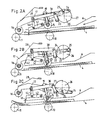
- the device performs a cycle of which Figs. 2A to 2E show a number of positions occupied consecutively.
- the disc 26 is put into the position shown in Fig. 2A, in which roller 33 is not in contact with the cam 27.
- rollers 11 and 16 form a nip
- rollers 10 and 15 are some distance apart
- abutment strip 41 is in the operative position
- the conveyor rollers 2 feed sheets individually to the tray 3. The sheets are positioned on one another and against abutment strip 41 and against side plate 5 by means not shown.
- the copying machine control system delivers a signal in response to which disc 26 is caused to rotate to perform one revolution, during which disc 26 successively occupies the positions shown in Figs. 2B to 2E.
- the end of the arm 17 formed with the slot 24, and the pressure roller 15 move down until this roller comes into contact with the sheets collected in tray 3.
- cam 27 has come into contact with roller 33 and the abutment strip 41 is lifted out of the bundle conveyor path.
- the driven roller 10 now conveys the bundle of sheets pressed thereagainst past abutment strip 41 in the direction of the roller pair 11, 16.
- the disc 26 rotating further has turned the arm 17 further in the same direction about the nip formed by pressure roller 15 with the bundle, thereby pressure roller 16 being lifted.
- the bundle of sheets in now fed unobstructedly between the rollers 11 and 16, which are disengaged from one another.
- the end 38 of arm 30 moves down and roller 33 disengages from cam 27, so that link 44 and arm 42 move down under their own weight until the abutment strip 41 encounters the top of the bundle.
- Fig. 2C shows the position now reached, in which pin 25 occupies the lowest position. With continuing rotation of disc 26, during which pin 25 moves up, arm 17 turns back until pressure roller 16 comes into contact with the advancing bundle of sheets.
- Fig. 2D shows the instantaneous position in which the two roller pairs 10, 15 and 11, 16 form a conveying nip.
- arm 17 turns about the nip formed by pressure roller 16 with the bundle, pressure roller 15 being disengaged from the bundle and only roller pair 11, 16 now forming a conveying nip.
- the sheets of the bundle cannot readily shift, e.g. due to a positioning means which, in order to position the sheets against abutment strip 41 and side plate 5, continually presses on the top sheet of the bundle.
- the above-described device can also be arranged to place the disc 26 from the inoperative postion shown in Fig. 1 into the position shown in Fig. 2D and stop it, while a cam (not shown) holds the arm 30 in the position shown in Fig. 1.
- a cam not shown
- sheets supplied individually from the conveyor path can be fed over the baseplate 4 of the tray 3 directly out of the copying machine. With this latter positioning, the sheets are not collected into bundles.
Landscapes
- Engineering & Computer Science (AREA)
- Mechanical Engineering (AREA)
- Delivering By Means Of Belts And Rollers (AREA)
- Pile Receivers (AREA)
Applications Claiming Priority (2)
| Application Number | Priority Date | Filing Date | Title |
|---|---|---|---|
| NL8503203A NL8503203A (nl) | 1985-11-21 | 1985-11-21 | Inrichting voor het transporteren van een bundel vellen. |
| NL8503203 | 1985-11-21 |
Publications (2)
| Publication Number | Publication Date |
|---|---|
| EP0224295A1 true EP0224295A1 (fr) | 1987-06-03 |
| EP0224295B1 EP0224295B1 (fr) | 1990-05-02 |
Family
ID=19846898
Family Applications (1)
| Application Number | Title | Priority Date | Filing Date |
|---|---|---|---|
| EP86201952A Expired EP0224295B1 (fr) | 1985-11-21 | 1986-11-10 | Dispositif de transport d'une pile de feuilles |
Country Status (5)
| Country | Link |
|---|---|
| US (1) | US4750853A (fr) |
| EP (1) | EP0224295B1 (fr) |
| JP (1) | JP2561080B2 (fr) |
| DE (1) | DE3670820D1 (fr) |
| NL (1) | NL8503203A (fr) |
Cited By (1)
| Publication number | Priority date | Publication date | Assignee | Title |
|---|---|---|---|---|
| WO1994016981A3 (fr) * | 1993-01-27 | 1994-10-27 | Boewe Systec Ag | Dispositif collecteur de feuilles__________________ |
Families Citing this family (35)
| Publication number | Priority date | Publication date | Assignee | Title |
|---|---|---|---|---|
| DE3731216A1 (de) * | 1987-09-17 | 1989-04-13 | Koenig & Bauer Ag | Vorrichtung zum zufuehren von bogen an eine bogenverarbeitende maschine, insbesondere druckmaschine |
| JP2536849Y2 (ja) * | 1990-02-16 | 1997-05-28 | 株式会社リコー | 後処理装置 |
| US5103982A (en) * | 1990-05-17 | 1992-04-14 | Bell & Howell Phillipsburg Company | Check stager-feeder |
| GB9103104D0 (en) * | 1991-02-14 | 1991-04-03 | Ncr Co | Sheet handling apparatus |
| GB9105151D0 (en) * | 1991-03-12 | 1991-04-24 | Ncr Co | Sheet handling apparatus |
| US5255906A (en) * | 1991-12-17 | 1993-10-26 | Pitney Bowes Inc. | Document registration apparatus |
| US5230504A (en) * | 1992-05-29 | 1993-07-27 | Pitney Bowes Inc. | Document registration apparatus with adjustment for handling documents of different lengths |
| US5263705A (en) * | 1992-06-29 | 1993-11-23 | Pitney Bowes Inc. | Document registration apparatus with skew adjustment |
| US5253861A (en) * | 1992-08-28 | 1993-10-19 | Pitney Bowes Inc. | Document registration apparatus with improvement to prevent shingling during removal of documents |
| US5356263A (en) * | 1992-12-16 | 1994-10-18 | Pitney Bowes Inc. | Buckle accumulator and method for accumulating sheets |
| US5350170A (en) * | 1993-07-21 | 1994-09-27 | Jon Emigh | Roller gap setting system |
| US5435542A (en) * | 1994-03-15 | 1995-07-25 | Interbold | Statement presenter mechanism for automated teller machine |
| US5462265A (en) * | 1994-11-07 | 1995-10-31 | Xerox Corporation | Variable force sheets or set ejector |
| US5566933A (en) * | 1995-01-30 | 1996-10-22 | Pitney Bowes Inc | Rail support for document queuing station |
| US5816773A (en) * | 1996-01-19 | 1998-10-06 | International Billing Services, Inc. | Collator apparatus |
| FR2744062B1 (fr) * | 1996-01-31 | 1998-04-30 | Neopost Ind | Dispositif d'entrainement optimise d'articles de courrier |
| JP3190247B2 (ja) * | 1996-03-13 | 2001-07-23 | キヤノン株式会社 | シート材給送装置及び画像形成装置 |
| GB2311985A (en) * | 1996-04-13 | 1997-10-15 | Xerox Corp | Controlling access to sheets at delivery port. |
| US5934668A (en) * | 1996-12-27 | 1999-08-10 | Pitney Bowes Inc. | Document registration apparatus with improved document drive capability |
| JPH1160024A (ja) * | 1997-08-28 | 1999-03-02 | Brother Ind Ltd | シート状媒体収納機構及び画像形成装置 |
| US6158572A (en) * | 1998-07-31 | 2000-12-12 | Ltv Steel Company, Inc. | Water driven roller for hot strip mill sideguides |
| US6551052B2 (en) * | 2001-07-12 | 2003-04-22 | Gbr Systems Corporation | Sheet and stack feeding mechanism |
| DE19953452C2 (de) * | 1999-11-03 | 2001-10-25 | Svedala Lindemann Gmbh | Einrichtung zum Beschicken einer Zerkleinerungsmaschine, wie z.B. Hammerbecher |
| US6439569B1 (en) * | 2000-12-19 | 2002-08-27 | Pitney Bowes Inc. | Sheet accumulator having a circular feed path |
| JP4160362B2 (ja) | 2002-10-30 | 2008-10-01 | グローリー株式会社 | 集積装置および循環式紙幣入出金機 |
| WO2004060777A2 (fr) * | 2002-12-31 | 2004-07-22 | Shuttleworth, Inc. | Galet d'avancement a compression |
| US7011304B2 (en) * | 2003-04-10 | 2006-03-14 | Dst Output, Inc. | Collator apparatus |
| US7034362B2 (en) * | 2003-10-17 | 2006-04-25 | International Business Machines Corporation | Double silicon-on-insulator (SOI) metal oxide semiconductor field effect transistor (MOSFET) structures |
| JP2006056654A (ja) * | 2004-08-19 | 2006-03-02 | Fuji Xerox Co Ltd | 用紙排出装置 |
| KR100739766B1 (ko) * | 2005-12-02 | 2007-07-13 | 삼성전자주식회사 | 레지스트레이션장치 및 이를 채용한 화상형성장치 |
| DE602007009614D1 (de) | 2006-08-22 | 2010-11-18 | Ricoh Kk | Blattausrichtungsvorrichtung und Bilderzeugungsvorrichtung damit |
| JP4750754B2 (ja) * | 2007-05-31 | 2011-08-17 | 株式会社リコー | シート搬送装置および画像形成装置 |
| JP2010064825A (ja) * | 2008-09-09 | 2010-03-25 | Toshiba Tec Corp | 印刷装置 |
| JP5874319B2 (ja) * | 2011-10-27 | 2016-03-02 | 富士ゼロックス株式会社 | 後処理装置及び画像形成システム |
| US12129146B2 (en) * | 2022-07-01 | 2024-10-29 | Xerox Corporation | Sheet path intersection device |
Citations (2)
| Publication number | Priority date | Publication date | Assignee | Title |
|---|---|---|---|---|
| GB1559898A (en) * | 1977-03-31 | 1980-01-30 | Xerox Corp | Sheet handling apparatus |
| US4453870A (en) * | 1982-03-08 | 1984-06-12 | The Mead Corporation | Accumulator |
Family Cites Families (4)
| Publication number | Priority date | Publication date | Assignee | Title |
|---|---|---|---|---|
| US3076196A (en) * | 1960-09-30 | 1963-02-05 | Mestre Luis | Stapling machine |
| US3618934A (en) * | 1970-05-18 | 1971-11-09 | Addressograph Multigraph | Feed roll assembly |
| JPS6050696B2 (ja) * | 1980-09-04 | 1985-11-09 | ロ−レルバンクマシン株式会社 | 紙葉類集積装置 |
| US4621966A (en) * | 1984-07-02 | 1986-11-11 | Pitney Bowes Inc. | Shingle compensating device |
-
1985
- 1985-11-21 NL NL8503203A patent/NL8503203A/nl not_active Application Discontinuation
-
1986
- 1986-11-10 DE DE8686201952T patent/DE3670820D1/de not_active Expired - Lifetime
- 1986-11-10 EP EP86201952A patent/EP0224295B1/fr not_active Expired
- 1986-11-11 JP JP61268485A patent/JP2561080B2/ja not_active Expired - Lifetime
- 1986-11-13 US US06/930,722 patent/US4750853A/en not_active Expired - Fee Related
Patent Citations (2)
| Publication number | Priority date | Publication date | Assignee | Title |
|---|---|---|---|---|
| GB1559898A (en) * | 1977-03-31 | 1980-01-30 | Xerox Corp | Sheet handling apparatus |
| US4453870A (en) * | 1982-03-08 | 1984-06-12 | The Mead Corporation | Accumulator |
Cited By (1)
| Publication number | Priority date | Publication date | Assignee | Title |
|---|---|---|---|---|
| WO1994016981A3 (fr) * | 1993-01-27 | 1994-10-27 | Boewe Systec Ag | Dispositif collecteur de feuilles__________________ |
Also Published As
| Publication number | Publication date |
|---|---|
| JP2561080B2 (ja) | 1996-12-04 |
| EP0224295B1 (fr) | 1990-05-02 |
| DE3670820D1 (de) | 1990-06-07 |
| NL8503203A (nl) | 1987-06-16 |
| JPS62121154A (ja) | 1987-06-02 |
| US4750853A (en) | 1988-06-14 |
Similar Documents
| Publication | Publication Date | Title |
|---|---|---|
| EP0224295B1 (fr) | Dispositif de transport d'une pile de feuilles | |
| JP4626902B2 (ja) | シート後処理装置 | |
| US4424660A (en) | Apparatus for binding paper sheets | |
| EP1117540A1 (fr) | Procede et appareil permettant de realiser des livrets ou des brochures | |
| EP0429639A1 (fr) | Appareil de sortie de documents a dispositif anti-endommagement | |
| US3982749A (en) | Signature feeder | |
| US5520603A (en) | Buckle chute folder with single selector knob for multimode folding operation | |
| JPH04226791A (ja) | 印刷製品の針金とじ装置 | |
| US4026199A (en) | Sheet end cutter and stripper | |
| JPH10324449A (ja) | シート処理装置 | |
| US4341299A (en) | Apparatus for performing operations on a stack of sheets | |
| US3692300A (en) | Feeder and folder arrangement for signature gathering machine | |
| JP3423875B2 (ja) | シート後処理装置 | |
| US4320547A (en) | Punch and binding machine | |
| JP4976246B2 (ja) | シート処理装置 | |
| JP3832964B2 (ja) | 用紙後処理装置および画像形成装置 | |
| US3883063A (en) | Punching and stapling apparatus | |
| US2771029A (en) | Web cutting and feeding device for printing machines | |
| US3691915A (en) | Stacking machine with mechanism for displacing stacked workpieces at spaced intervals | |
| US4216953A (en) | Paper feeding device | |
| JP3907795B2 (ja) | 用紙綴じ機 | |
| GB2175251A (en) | Book binding machine | |
| JPH11314838A (ja) | シ―トを2つ折りするための折畳み装置 | |
| JP3474048B2 (ja) | 用紙後処理装置 | |
| JPH019797Y2 (fr) |
Legal Events
| Date | Code | Title | Description |
|---|---|---|---|
| PUAI | Public reference made under article 153(3) epc to a published international application that has entered the european phase |
Free format text: ORIGINAL CODE: 0009012 |
|
| AK | Designated contracting states |
Kind code of ref document: A1 Designated state(s): DE FR GB NL |
|
| 17P | Request for examination filed |
Effective date: 19871119 |
|
| 17Q | First examination report despatched |
Effective date: 19890117 |
|
| GRAA | (expected) grant |
Free format text: ORIGINAL CODE: 0009210 |
|
| AK | Designated contracting states |
Kind code of ref document: B1 Designated state(s): DE FR GB NL |
|
| REF | Corresponds to: |
Ref document number: 3670820 Country of ref document: DE Date of ref document: 19900607 |
|
| ET | Fr: translation filed | ||
| PLBE | No opposition filed within time limit |
Free format text: ORIGINAL CODE: 0009261 |
|
| STAA | Information on the status of an ep patent application or granted ep patent |
Free format text: STATUS: NO OPPOSITION FILED WITHIN TIME LIMIT |
|
| 26N | No opposition filed | ||
| NLT1 | Nl: modifications of names registered in virtue of documents presented to the patent office pursuant to art. 16 a, paragraph 1 |
Owner name: OCE-TECHNOLOGIES B.V. |
|
| PGFP | Annual fee paid to national office [announced via postgrant information from national office to epo] |
Ref country code: FR Payment date: 19991011 Year of fee payment: 14 |
|
| PGFP | Annual fee paid to national office [announced via postgrant information from national office to epo] |
Ref country code: GB Payment date: 19991020 Year of fee payment: 14 |
|
| PGFP | Annual fee paid to national office [announced via postgrant information from national office to epo] |
Ref country code: DE Payment date: 19991028 Year of fee payment: 14 |
|
| PGFP | Annual fee paid to national office [announced via postgrant information from national office to epo] |
Ref country code: NL Payment date: 19991122 Year of fee payment: 14 |
|
| PG25 | Lapsed in a contracting state [announced via postgrant information from national office to epo] |
Ref country code: GB Free format text: LAPSE BECAUSE OF NON-PAYMENT OF DUE FEES Effective date: 20001110 |
|
| PG25 | Lapsed in a contracting state [announced via postgrant information from national office to epo] |
Ref country code: NL Free format text: LAPSE BECAUSE OF NON-PAYMENT OF DUE FEES Effective date: 20010601 |
|
| GBPC | Gb: european patent ceased through non-payment of renewal fee |
Effective date: 20001110 |
|
| PG25 | Lapsed in a contracting state [announced via postgrant information from national office to epo] |
Ref country code: FR Free format text: LAPSE BECAUSE OF NON-PAYMENT OF DUE FEES Effective date: 20010731 |
|
| NLV4 | Nl: lapsed or anulled due to non-payment of the annual fee |
Effective date: 20010601 |
|
| PG25 | Lapsed in a contracting state [announced via postgrant information from national office to epo] |
Ref country code: DE Free format text: LAPSE BECAUSE OF NON-PAYMENT OF DUE FEES Effective date: 20010801 |
|
| REG | Reference to a national code |
Ref country code: FR Ref legal event code: ST |