EP0224387A2 - Spender und Vorrichtung zum Spenden eines Produktes - Google Patents
Spender und Vorrichtung zum Spenden eines Produktes Download PDFInfo
- Publication number
- EP0224387A2 EP0224387A2 EP86309126A EP86309126A EP0224387A2 EP 0224387 A2 EP0224387 A2 EP 0224387A2 EP 86309126 A EP86309126 A EP 86309126A EP 86309126 A EP86309126 A EP 86309126A EP 0224387 A2 EP0224387 A2 EP 0224387A2
- Authority
- EP
- European Patent Office
- Prior art keywords
- container
- disc
- dispenser
- apertured
- guide tube
- Prior art date
- Legal status (The legal status is an assumption and is not a legal conclusion. Google has not performed a legal analysis and makes no representation as to the accuracy of the status listed.)
- Withdrawn
Links
Images
Classifications
-
- A—HUMAN NECESSITIES
- A45—HAND OR TRAVELLING ARTICLES
- A45D—HAIRDRESSING OR SHAVING EQUIPMENT; EQUIPMENT FOR COSMETICS OR COSMETIC TREATMENTS, e.g. FOR MANICURING OR PEDICURING
- A45D40/00—Casings or accessories specially adapted for storing or handling solid or pasty toiletry or cosmetic substances, e.g. shaving soaps or lipsticks
- A45D40/02—Casings wherein movement of the lipstick or like solid is a sliding movement
- A45D40/04—Casings wherein movement of the lipstick or like solid is a sliding movement effected by a screw
-
- A—HUMAN NECESSITIES
- A45—HAND OR TRAVELLING ARTICLES
- A45D—HAIRDRESSING OR SHAVING EQUIPMENT; EQUIPMENT FOR COSMETICS OR COSMETIC TREATMENTS, e.g. FOR MANICURING OR PEDICURING
- A45D40/00—Casings or accessories specially adapted for storing or handling solid or pasty toiletry or cosmetic substances, e.g. shaving soaps or lipsticks
- A45D40/0068—Jars
- A45D40/0075—Jars with dispensing means
Definitions
- This invention relates to a material dispenser, and particularly, but not exclusively, to a dispenser for a creamy, paste-like or viscous cosmetics product.
- the invention also relates to a dispenser device to be fitted to a container.
- Thick creamy cosmetics products such as cold cream
- Thick creamy cosmetics products are commonly supplied in wide-necked pots or jars.
- the user simply removes the lid of the jar and scoops out the required amount of the product using a finger or fingers. This procedure is not only messy, but is also uneconomical as the user will ofter scoop out more material than is actually required.
- the present invention aims to provide an improved material dispenser and device which overcome these problems.
- a dispenser for a creamy, paste-like or viscous material comprising a rigid-wall container for the material and dispensing means in which an apertured element is disposed so as to cover a quantity of said material in the container, and in which manually operable means is provided for forcing material form said quantity through the aperture or apertures in said member onto an outer face thereof from which said material can be removed.
- the apertured element may be in the form of a disc which forms part of a dispensing device fitted into the neck of the container.
- Other elements of this device cooperate so as to force the disc onto the material accommodated within the container beneath the disc, thereby forcing the material by hydraulic pressure to ooze through an aperture formed at the centre of the disc.
- These elements may include a manually rotatable annular flange disposed at the mouth of the container neck, and a mechanism by which rotation of this flange drives the apertured disc downwardly relative to the quantity of material disposed beneath the disc.
- the flange is attached to, or integrally formed with a guide tube which projects downwardly into the container and which is formed with a plurality of circumferentially spaced and axially extending slots.
- the disc is a close-fit within this guide tube, and is formed with a plurality of radially outwardly projecting spigots which extend through the slots in the guide tube into respective helical grooves formed in the inner surface of an outer sleeve in which the guide tube is coaxially and rotatably fitted, this grooved sleeve being rotationally fixed relative to the container neck.
- Means may be provided to indicate to the user increments of axial movement of the apertured member relative to the quantity of material, thereby permitting preset amounts of the material to be delivered through the aperture or apertures.
- This latter means may take the form of a ratchet mechanism indicating increments of rotation of the aforesaid manually rotatable flange.
- This ratchet mechanism may further be adapted for one-way rotation, thereby ensuring that the apertured disc can be moved only in the material-dispensing direction.
- a dispenser device adapted to be fitted to a container for dispensing a creamy, paste-like or viscous material contained in the container, the device having an apertured cover member for covering the material, and a member adapted to be movably mounted relatively to the container, said member having a portion which, when the device is fitted to the container, is disposed so that it can be manually engaged and moved, the device including an element which is coupled to be moved in response to movement of said member to press on the material and force some of it through the aperture or apertures in said cover member onto an outer face thereof.
- the presser element and the apertured cover are one and the same component and comprise an apertured disc fitted within a cylindrical guide tube constituting the movable member, and arranged to move axially therein in response to rotation of such tube.
- This tube has at its end which will project from an opening of the container, a manually engageable annular flange by which it can be rotated about its axis.
- the guide tube may be formed with axially extending slots through which circumferentially spaced radially projecting spigots formed at the periphery of the disc, project, outer portions of such spigots being located in respective helical slots formed in a cylindrical wall of the container, or formed in an outer attachment tube, also part of the device, fixed within the container.
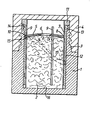
- the accompanying drawing is a longitudinal section through a container for dispensing a cosmetic product in accordance with the invention.
- the illustrated dispensing container comprises a rigid-walled hollow body portion 1 for containing a quantity of the product 2 and having an externally screw-threaded neck 3.
- a cap 4 is formed with internal-screw-threading complementary to the screw-threading on the neck 3.
- a dispensing mechanism disposed within the container body 1 includes a disc 5 which contacts and covers over the top of the material 2 and which is arranged to be driven downwardly onto the material. This disc is formed with an aperture in the form of a central slot 6 through which material is forced upwardly when the disc is forced downwardly.
- the disc is fitted within an inner guide tube 7, the circumference of the disc forming a sealing engagement 8 with the inner cylindrical surface of this guide tube.
- the guide tube 7 is formed with a number of circumferentially spaced elongate axially extending slots 9 (through one of which the section of the drawing passes), and a corresponding plurality of radially extending spigots 10 formed at circumferentially spaced points on the circumference of the disc extend outwardly through these slots 9.
- the guide tube 7 is formed at its upper end with a manually engageable outwardly extending flange 11 which sits on top of the mouth of the neck 3.
- a cylindrical attachment tube 12 is fixedly located within the container; in this embodiment, the container is formed with a cylindrical bore within which this attachment tube force-fits.
- the upper end of this attachment tube is formed with an outwardly projecting annular sealing flange 13 which fits in an internal annular rebate 14 formed in the container neck.
- the inner cylindrical surface of the attachment tube 12 has a number of helical grooves 15 formed so as to receive the outermost portions of respective ones of the radially projecting spigots of the disc 5.
- the number of spigots, slots and helical grooves is such as to ensure that the disc 5 remains properly and stably positioned within the guide tube 7 as it moves axially. For the sake of clarity, only one of these grooves is shown in the drawing.
- the disc is initially positioned at the top of the guide tube, and the whole of the space defined beneath the disc by the base surface 16 of the container and the inner cylindrical surface of the guide tube 7 is filled with the creamy, paste-like or viscous cosmetics material 2.
- the user will grip the outer edge of the flange 11, which may be ribbed or knurled for this purpose, and will rotate it relative to the body 1 of the container. Accordingly, the guide tube 7 will be rotated, and the disc 5 will thereby be forced to rotate by virtue of the engagement of its spigots with the edges of the slots 9 in the guide tube. Such rotation of the disc will cause the spigots to move along the respective helical grooves 15, so causing the disc to move axially within the guide tube.
- the user can readily remove the material now lying on top of the disc using a finger or suitable applicator, and in this way the need to insert the finger or the applicator into the mass of the material within the container, as was hitherto necessary with the conventional pot-type container, is obviated, and a much cleaner and better regulated procedure for dispensing the material is provided.
- the amount of axial movement of the disc, and thereby the amount of material delivered through the slot onto the upper side of the disc will depend upon the amount by which the flange 11 is rotated.
- some means may be provided for indicating to the user equal increments of rotation of the flange 11.
- a ratchet mechanism between the flange 11 and the neck of the container may provide clicks which can be felt by the user when rotating the flange and which indicate these equal increments of rotation.
- the arrangement is such as to ensure that the flange 11 can be rotated only in the direction which causes downward movement of the disc.
- the above-mentioned ratchet mechanism may be adapted to provide this one-way rotation of the flange and guide tube.
- the mechanism for driving the disc includes an outer attachment tube 12 fixed in the container, it is possible to simplify the construction of the driving mechanism by dispensing with such attachment tube and forming the helical grooves in the inner cylindrical wall 17 of the container itself.
- the apertured disc it is not essential to arrange for the apertured disc to move. It would, for example, be possible to arrange the disc in an axially fixed positioned adjacent the top of the container (e.g. fixed to or integral with the flange 11) and to provide a solid disc which is initially positioned adjacent the base surface 16 of the container and which is driven upwardly by the relative rotation of the guide tube 7 and the attachment tube 12 (or the inner wall of the container) so as to push the bulk of the cosmetics material upwardly, causing the required quantity of the material to be forced through the slot in the axially fixed upper disc.
- the disc in an axially fixed positioned adjacent the top of the container (e.g. fixed to or integral with the flange 11) and to provide a solid disc which is initially positioned adjacent the base surface 16 of the container and which is driven upwardly by the relative rotation of the guide tube 7 and the attachment tube 12 (or the inner wall of the container) so as to push the bulk of the cosmetics material upwardly, causing the required quantity of the material to be forced
Landscapes
- Closures For Containers (AREA)
Applications Claiming Priority (2)
| Application Number | Priority Date | Filing Date | Title |
|---|---|---|---|
| GB858528800A GB8528800D0 (en) | 1985-11-22 | 1985-11-22 | Material dispenser |
| GB8528800 | 1985-11-22 |
Publications (2)
| Publication Number | Publication Date |
|---|---|
| EP0224387A2 true EP0224387A2 (de) | 1987-06-03 |
| EP0224387A3 EP0224387A3 (de) | 1987-11-25 |
Family
ID=10588619
Family Applications (1)
| Application Number | Title | Priority Date | Filing Date |
|---|---|---|---|
| EP86309126A Withdrawn EP0224387A3 (de) | 1985-11-22 | 1986-11-21 | Spender und Vorrichtung zum Spenden eines Produktes |
Country Status (2)
| Country | Link |
|---|---|
| EP (1) | EP0224387A3 (de) |
| GB (1) | GB8528800D0 (de) |
Cited By (2)
| Publication number | Priority date | Publication date | Assignee | Title |
|---|---|---|---|---|
| FR2706865A1 (en) * | 1993-06-22 | 1994-12-30 | Geiger Sarl | Tube and fluted stopper |
| WO2005030313A1 (en) * | 2003-09-26 | 2005-04-07 | Lameplast S.P.A. | Cannula for dispensing fluid products for vaginal and anal applications |
Family Cites Families (10)
| Publication number | Priority date | Publication date | Assignee | Title |
|---|---|---|---|---|
| FR451064A (fr) * | 1912-11-27 | 1913-04-10 | Edward Tilston | Perfectionnements apportés aux flacons et bocaux |
| FR666392A (fr) * | 1928-01-19 | 1929-10-01 | Perfectionnements aux boîtes pour crèmes de beauté et produits semi-liquides analogues | |
| FR768271A (fr) * | 1934-02-08 | 1934-08-03 | Récipient pour la distribution de substances et en particulier de substances pâteuses | |
| DE949121C (de) * | 1953-05-23 | 1956-09-13 | Koe Pa Kelner Parfuemerie Apot | Geraet zur Abgabe regelbarer Mengen teigiger Massen |
| DE1125837B (de) * | 1960-07-12 | 1962-03-15 | Josef Gabler | Dose zur Aufnahme und Abgabe pastenfoermiger Stoffe |
| FR1323631A (fr) * | 1962-02-27 | 1963-04-12 | Guerlain | Distributeur de crème |
| US3241729A (en) * | 1964-11-16 | 1966-03-22 | Gabler Josef | Dispensers for cosmetic and medicinal preparations |
| FR2355732A1 (fr) * | 1975-09-10 | 1978-01-20 | Obbergen Francois Van | Dispositif de conservation pour produits cosmetiques et analogues |
| EP0109982A1 (de) * | 1982-12-07 | 1984-06-13 | Willi Merz | Gerät zum Verteilen und/oder Auftragen einer teig- oder cremartigen Substanz |
| FR2559135B1 (fr) * | 1984-02-07 | 1986-10-10 | Besins Iscovesco Laboratoires | Distributeur-doseur d'un produit pateux |
-
1985
- 1985-11-22 GB GB858528800A patent/GB8528800D0/en active Pending
-
1986
- 1986-11-21 EP EP86309126A patent/EP0224387A3/de not_active Withdrawn
Cited By (3)
| Publication number | Priority date | Publication date | Assignee | Title |
|---|---|---|---|---|
| FR2706865A1 (en) * | 1993-06-22 | 1994-12-30 | Geiger Sarl | Tube and fluted stopper |
| WO2005030313A1 (en) * | 2003-09-26 | 2005-04-07 | Lameplast S.P.A. | Cannula for dispensing fluid products for vaginal and anal applications |
| US7507223B2 (en) | 2003-09-26 | 2009-03-24 | Lameplast S.P.A. | Cannula for dispensing fluid products for vaginal and anal applications |
Also Published As
| Publication number | Publication date |
|---|---|
| GB8528800D0 (en) | 1985-12-24 |
| EP0224387A3 (de) | 1987-11-25 |
Similar Documents
| Publication | Publication Date | Title |
|---|---|---|
| US4865231A (en) | Button type dispensing package | |
| EP0355156B1 (de) | Stiftverpackung mit auftragsfläche | |
| US4580920A (en) | Stick dispenser | |
| US5025960A (en) | Dispenser with hollow drive rod | |
| US5868510A (en) | Product dispenser having a rotary drive member, and a method of manufacture | |
| RU2201121C2 (ru) | Дозирующая упаковка | |
| US6923347B2 (en) | Assembly for packaging a product, especially a cosmetic product | |
| AU762343B2 (en) | Exact dose dispenser device assembly | |
| US4595124A (en) | Semi-solid cylindrical container and dispenser | |
| US6089774A (en) | Refillable container for applying a spreadable product, more particularly an adhesive compound | |
| EP0645972B1 (de) | Spendergerät mit hebewerk und gewindestange für stiftförmiges gut und ersatzpatrone dafür | |
| US4020975A (en) | Wall-mountable dispensing device for bulk and encapsulated materials | |
| US4437584A (en) | Toothpaste dispenser | |
| JPH0219290A (ja) | 製品分与装置 | |
| JP2549734B2 (ja) | 粘性物質用分与容器 | |
| US6210061B1 (en) | Dispensing apparatus | |
| HK1007476B (en) | Stick package with applicator surface | |
| EP0561322B1 (de) | Tropfflasche für zwei vor dem Gebrauch zu vermischende Produkte | |
| NZ226579A (en) | Dispensing package for cream products: cams on cantilevered fingers produce reciprocating axial movement of elevator | |
| US4921130A (en) | Viscous material dispensing apparatus | |
| EP0224387A2 (de) | Spender und Vorrichtung zum Spenden eines Produktes | |
| US20110127299A1 (en) | Dispenser for spreadable food | |
| EP1056658B1 (de) | Spender mit umkehrbarer bewegung | |
| US5727891A (en) | Ointment dispenser with kick-start mechanism | |
| EP0100204A1 (de) | Applikator für Cremes und zähflüssige Flüssigkeiten |
Legal Events
| Date | Code | Title | Description |
|---|---|---|---|
| PUAI | Public reference made under article 153(3) epc to a published international application that has entered the european phase |
Free format text: ORIGINAL CODE: 0009012 |
|
| AK | Designated contracting states |
Kind code of ref document: A2 Designated state(s): DE FR GB |
|
| PUAL | Search report despatched |
Free format text: ORIGINAL CODE: 0009013 |
|
| AK | Designated contracting states |
Kind code of ref document: A3 Designated state(s): DE FR GB |
|
| STAA | Information on the status of an ep patent application or granted ep patent |
Free format text: STATUS: THE APPLICATION IS DEEMED TO BE WITHDRAWN |
|
| 18D | Application deemed to be withdrawn |
Effective date: 19880526 |