EP0224450B1 - Machine pour former une enveloppe en papier sur des rouleaux de bande métallique de l'industrie sidérurgique - Google Patents
Machine pour former une enveloppe en papier sur des rouleaux de bande métallique de l'industrie sidérurgique Download PDFInfo
- Publication number
- EP0224450B1 EP0224450B1 EP86830321A EP86830321A EP0224450B1 EP 0224450 B1 EP0224450 B1 EP 0224450B1 EP 86830321 A EP86830321 A EP 86830321A EP 86830321 A EP86830321 A EP 86830321A EP 0224450 B1 EP0224450 B1 EP 0224450B1
- Authority
- EP
- European Patent Office
- Prior art keywords
- coil
- paper
- arm
- folding devices
- axis
- Prior art date
- Legal status (The legal status is an assumption and is not a legal conclusion. Google has not performed a legal analysis and makes no representation as to the accuracy of the status listed.)
- Expired
Links
- 239000002184 metal Substances 0.000 title claims description 4
- 229910052751 metal Inorganic materials 0.000 title claims description 4
- 229910000831 Steel Inorganic materials 0.000 title description 2
- 239000010959 steel Substances 0.000 title description 2
- XEEYBQQBJWHFJM-UHFFFAOYSA-N Iron Chemical compound [Fe] XEEYBQQBJWHFJM-UHFFFAOYSA-N 0.000 title 2
- 229910052742 iron Inorganic materials 0.000 title 1
- 239000000463 material Substances 0.000 claims description 2
- 230000000284 resting effect Effects 0.000 claims description 2
- 238000005452 bending Methods 0.000 claims 2
- 230000000712 assembly Effects 0.000 description 4
- 238000000429 assembly Methods 0.000 description 4
- 238000004806 packaging method and process Methods 0.000 description 1
- 238000012856 packing Methods 0.000 description 1
- 238000004804 winding Methods 0.000 description 1
Images

Classifications
-
- B—PERFORMING OPERATIONS; TRANSPORTING
- B65—CONVEYING; PACKING; STORING; HANDLING THIN OR FILAMENTARY MATERIAL
- B65B—MACHINES, APPARATUS OR DEVICES FOR, OR METHODS OF, PACKAGING ARTICLES OR MATERIALS; UNPACKING
- B65B11/00—Wrapping, e.g. partially or wholly enclosing, articles or quantities of material, in strips, sheets or blanks, of flexible material
- B65B11/04—Wrapping, e.g. partially or wholly enclosing, articles or quantities of material, in strips, sheets or blanks, of flexible material the articles being rotated
-
- B—PERFORMING OPERATIONS; TRANSPORTING
- B65—CONVEYING; PACKING; STORING; HANDLING THIN OR FILAMENTARY MATERIAL
- B65B—MACHINES, APPARATUS OR DEVICES FOR, OR METHODS OF, PACKAGING ARTICLES OR MATERIALS; UNPACKING
- B65B49/00—Devices for folding or bending wrappers around contents
- B65B49/12—Rotary folders
Definitions
- the present invention relates to a machine for wrapping a sheet of thick paper -or similar material- around metal strip coils.
- the paper wrapping is required before the coil is enclosed in a rigid packaging and, especially, in a metal one.
- the machine operates in association with a paper roll feeder and with a system of rolls for revolving the coil and includes the features defined in claim 1 divided into two parts with regard to the disclosure of DE-B-1181118.
- the discs of the primary folding devices include frustoconical slanted edges, which flank the cylindrical surface of the coil and which can be associated with guide rolls.
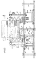
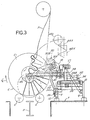
- FIG. 1 the frontal elevation and layout plan of the machine are shown respectively in Figures 1 and 2, while Fig. 3 is a side-view of the machine in the direction of the axis of the coil.
- a machine works in association with a coil transfer system that serves a number of stations.
- the transfer system includes a beam (3) working with a series of lifting, advancing, backing and lowering movements to move coils (C) to different stations, in at least part of which (and especially at the station where the machine in question is installed), provision is made for lowering coil C onto a set of rolls (5), so that the coil can revolve in the direction indicated by the arrow f C (Fig.3) during the wrapping operation, which begins the packing of coils and is followed by other operations to form a casing (that is usually made using another equipement).
- the coils travel in a direction parallel to their axis, while the machine according to the invention is installed on a basement (7) facing the station that is fitted with the supporting rolls (5) on which the coil to be wrapped in paper revolves.
- Basement (7) carries a steel frame (9) that supports two rails or tracks (10), laid parallel to the axis of coil C and to the direction of travel of the coils when they pass from one station to the next (i.e. in the direction of arrow f A or in the opposite direction).
- a hinged arm (14) pivots at one end on a pin (12) installed centrally on frame (9) (Figs 1 & 2) and is fitted, at the opposite end, with a single median guide roll (16) or with a set of coaxial guide rolls resting on the cylindrical surface of coil C.
- the guide roll, or rolls can be backed away from the cylindrical surface of the coil by a hydraulic actuator (18) which is hinged at (20) to frame (9) and, at the opposite end, at (22) to arm (14); guide roll (16) can therefore be pulled away from or pushed towards coil C by operating hydraulic actuator (18).
- the two carriages (24) can be power-driven or made to slide manually along rails (10) so as to approach, or back away from, each other and to reach symmetrical, or asymmetrical, positions with respect to the centre of frame (9).
- Each carriage (24) supports one set of primary folding devices and one set of secondary folding devices. More precisely, each carriage (24) is fitted with a hinged arm (28), similar to arm (14), which pivots at (26) on a bracket (24A) fixed to the carriage underside.
- Arm (28) carries the said primary folding devices, indicated generically as (30) and comprising a bevelled disk (30A) and a second disk (30B) similar to guide roll (16).
- Disk (30B) rests on the cylindrical surface of the coil, while disk (30A) presses against the circular side (C1) of the coil.
- Bevelled disk 30A of the primary folding devices can be backed away from, or pressed against, the circular side (C1) of the coil by sliding carriage (24) in the required direction.
- Arm (28) like arm (14), can be pulled away from, or pushed towards, the cylindrical surface of the coil by a hydraulic actuator (32) hinged, at one end, to point (34) of the carriage and, at the opposite end, to point (36) of arm (28) so that both disks can be moved towards or away from the coil.
- Each carriage (24) is fitted with a pair of short upright supports (24B) that hold above the carriage a horizontal shaft (38) which is parallel to the axis of the coil (i.e. to rails 10) and on which pivots an assembly (39).
- Assembly (39) includes a journal box for the hub of a rotor (40); rotor (40) is installed with its shaft at right angles to the axis of shaft (38) and is coupled to a stiff self-supporting helix or screw roller (42), the axis of which latter lies in a plane at right-angles to the axis of coil C.
- Rotor (40) and helix (42) are driven by a geared motor (37), forming part of the said assembly (39) which pivots on shaft (38).
- Screw roller (42) can consist of bar twisted into the shape of a cylindrical helix; the outer edge of screw roller (42) is rounded and the winding of the helix is almost parallel to the lie of the bevel of disk (30A) of the primary folding devices. Helix (42) forms part of the primary folding devices and completes the first folding operation in the manner described later in this specification.
- Assembly (39) also includes a hinged arm (44) pivoting on shaft (38) and positioned, in each of the two assemblies mounted on carriages (24), externally to helix (42) of the primary folding devices.
- Each arm (44) carries a secondary folding device (46) on its far end, consisting of a helix screw roller similar to helix (42) but with its axis parallel to the axis of coil C.
- the helix (46) is developed inwards, that is in the direction of the helix of the opposite rotor mounted on the other carriage.
- Each screw roller (46), that is each secondary folding device is driven by a geared motor (48) mounted on arm (44).
- actuator (50) By operating actuator (50), it is possible to lower arm (44), rotor (40) and helix (42) (installed on the relative carriage (24)) jointly to a near-horizontal position (indicated in the drawing by unbroken lines) or to raise them to an essentially vertical position, as shown in Figures 1 and 3 (chain-line sketches (44X), (46X) and (42X)).
- the various operative components of assembly (39) are removed from the path of coils existing and entering the wrapping station.
- the machine operates in the following manner.
- an automatic dispenser located above the wrapping station feeds out a continuous sheet of paper (N) whose width is greater than that of the cylindrical surface of the coil, so that the sheet can be laid on the cylindrical surface of the coil and then folded onto the circular sides (C1) and into the hollow core (F) of the coil.
- Sheet (N) is led onto the cylindrical surface of the coil and then wraped by the primary folding devices which, in the meantime, have been lowered from the vertical position (42X) to a near-horizontal position (rotors (40) and helix (42)) and moved towards the coil (disks (30A) and (30B)) so as to start pleating sheet (N).
- Guide roll (16) and disks (30B) and (30A) are moved towards the coil either before or immediately after the paper sheet first reaches the cylindrical surface of the coil; the paper sheet is also drawn in between the coil and rolls (5) which support the coil and make it revolve.
- the open ends of sheet (N) are pleated against the circular sides (C1) of the coil (C) by bevelled disks (30A) and by screw rollers (42).
- screw rollers (46) which have been inserted to a certain depth in hollow core (F), take over and fold back the edges of the paper ends wrapped around the coil by bevelled disks (30A) and screw rollers (42).
- the pleated edges are inserted into hollow core (F) and are flattened against the inner wall of the coil, sheathing hollow core (F) up to a certain distance from each end and even making one pleated edge overlap the opposite one at the centre of the core.
- the entire wrapping operation is completed during a 360° revolution of coil (C), during which sheet (N) is drawn onto the cylindrical surface and follows the rotary movement of the coil.
- the paper can be fed out either in pre-cut lengths, each sufficient for one wrapping operation, or from a continuous paper reel and cut at the end of each operation; the terminal edge of the sheet wrapped round the coil is then secured in place with a simple fixing operation.
- the two carriages (24) are backed sway from one another so as to withdraw screw rollers (46) from hollow core (F); guide rolls (16) and disk (30B) are then moved away from the cylindrical surface of the coil by swinging back arms (14) and (28) on their pivots, while screw rollers (42) and (46) are raised to their vertical positions (42X) and (46X) by pivoting upwards assemblies (39) by means of actuators (50).
- all components are positioned so that they cannot interfere with or impede the axial progress of the outgoing coil or of the next coil entering the station.
- Screw rollers (42) and (46) can be advantageously made of helical rods or rods of similar shape and can be sheathed with rubber or with other similar material.
Landscapes
- Engineering & Computer Science (AREA)
- Mechanical Engineering (AREA)
- Packaging Of Special Articles (AREA)
- Basic Packing Technique (AREA)
Claims (2)
- Machine pour enrouler une feuille de papier épais - ou un matériau épais similaire - autour d'une bobine de ruban métallique qui est associés à un dispensateur fournissant une feuille de papier (N) et à un système permettant de tourner une bobine (C) sur un certain nombre de rouleaux d'appui (5) et comprenant aussi: (i) des rouleaux-guide (16, 30B) s'appuyant sur la surface cylindrique de la bobine; (ii) les dispositifs plieurs primaires (30A, 42), bordant ladite surface cylindrique de la bobine, pour plier et plisser les bouts ouverts du papier contre les cotés circulaires (C1) de la bobine; (iii) les dispositifs plieurs secondaires (46) pour plier en arrière les bords du papier dans le noyau creux (F) de la bobine, se caractérisant par le fait que lesdits dispositifs plieurs primaires comportent des disques inclinables (30A) qui bordent lesdits cotés circulaires (C1) de la bobine et qui peuvent elle associés aux rouleaux-guides (30B) et les premiers rouleaux à vis (42), les dispositifs de pliage primaire et secondaire sont montés sur deux chariots (24) sur un chassis (9) présentant deux rails (10) parallèles à l'axe de la bobine, le premier et le deuxième bras (28, 24B) sont disposés sur chaque chariot (24) se déplaçant le long des rails (10) et s'articulent sur les arbres (26, 38) parallèles à l'axe de la bobine, chaque bras étant mu par un vérin hydraulique (32, 50); le premiere bras (28) porte le disque inclinable (30A) et si cela est possible un rouleau-guide (30B), le deuxième bras (24B) porte le premier rouleau à vis (42) qui tourne sur un arbre parallèle audit coté circulaire (C1) de la bobine, dans le sens de la rotation ce qui favorise le plissement par le bord hélicoidal arrondi et le dispositif plieur secondaire formé par un deuxième rouleau à vis (46) qui tourne sur un arbre parallèle à l'axe de la bobine et qui peut elle inséré à une certaine profondeur à l'intérieur ou éloigné du noyau creux de la bobine.
- Machine conforme à la revendication 1, se caractérisant par le fait que disques inclinables dont il y est question présentent une configuration en tronc de cone.
Applications Claiming Priority (2)
| Application Number | Priority Date | Filing Date | Title |
|---|---|---|---|
| IT09529/85A IT1201387B (it) | 1985-11-28 | 1985-11-28 | Macchina per formare l'involucro cartaceo su bobine di lamiera metallica (coils)dell'industria siderurgica |
| IT952985 | 1985-11-28 |
Publications (3)
| Publication Number | Publication Date |
|---|---|
| EP0224450A2 EP0224450A2 (fr) | 1987-06-03 |
| EP0224450A3 EP0224450A3 (en) | 1988-03-23 |
| EP0224450B1 true EP0224450B1 (fr) | 1992-04-15 |
Family
ID=11131686
Family Applications (1)
| Application Number | Title | Priority Date | Filing Date |
|---|---|---|---|
| EP86830321A Expired EP0224450B1 (fr) | 1985-11-28 | 1986-11-04 | Machine pour former une enveloppe en papier sur des rouleaux de bande métallique de l'industrie sidérurgique |
Country Status (7)
| Country | Link |
|---|---|
| US (1) | US4819408A (fr) |
| EP (1) | EP0224450B1 (fr) |
| JP (1) | JPS62135109A (fr) |
| CA (1) | CA1267070A (fr) |
| DE (1) | DE3684886D1 (fr) |
| IT (1) | IT1201387B (fr) |
| NO (1) | NO864727D0 (fr) |
Families Citing this family (7)
| Publication number | Priority date | Publication date | Assignee | Title |
|---|---|---|---|---|
| GB8821033D0 (en) * | 1988-09-07 | 1988-10-05 | Wrap A Round Ltd | Bulk material packaging apparatus |
| US5546729A (en) * | 1994-11-15 | 1996-08-20 | Automatic Handling Inc. | Wrapping machine |
| US5775515A (en) * | 1996-05-06 | 1998-07-07 | Chadwick Engineering Limited | Method and apparatus for wrapping coils, and the wrapped product |
| ITFI20120187A1 (it) * | 2012-09-20 | 2014-03-21 | Kpl Packaging Spa | "macchina confezionatrice per confezionare rotoli avvolti su anime tubolari" |
| CN103112622B (zh) * | 2013-03-08 | 2014-11-26 | 广东省韶关烟草机械配件厂有限公司 | 条盒透明纸端面折叠成型装置及其应用 |
| CN106938713B (zh) * | 2017-04-10 | 2023-02-17 | 成都三可实业有限公司 | 颗粒口香糖条形包装机 |
| CN108502230B (zh) * | 2018-07-05 | 2024-02-20 | 河北国创石油设备有限公司 | 直线电机初级线圈缠膜机 |
Family Cites Families (12)
| Publication number | Priority date | Publication date | Assignee | Title |
|---|---|---|---|---|
| US2927413A (en) * | 1958-03-24 | 1960-03-08 | Lamb Grays Harbor Co Inc | Roll crimping machines |
| US2919527A (en) * | 1958-03-31 | 1960-01-05 | John K Smith | Wrapping and packaging machine |
| DE1181118B (de) * | 1960-07-04 | 1964-11-05 | John Kouloukas Smith | Verpackungsmaschine zum Einwickeln einer Rolle in eine Huellmaterialbahn |
| US3411269A (en) * | 1965-07-15 | 1968-11-19 | Beloit Eastern Corp | Crimper paddle |
| FR2030507A5 (fr) * | 1969-01-30 | 1970-11-13 | Neyrpic Bmb | |
| US3577703A (en) * | 1969-02-12 | 1971-05-04 | Nordstroms Libanor Ab | Means for folding in wrapping material at the end of an approximately cylindrical article |
| US3605382A (en) * | 1969-05-06 | 1971-09-20 | Erik Andersson | Machine for wrapping rolls |
| US3633335A (en) * | 1969-08-29 | 1972-01-11 | James Brinkley Co Inc | Roll end capper |
| US3828523A (en) * | 1972-11-20 | 1974-08-13 | Beloit Corp | Automatic inside head holder structure |
| US3807132A (en) * | 1972-11-22 | 1974-04-30 | I Kamiya | Wrapping machine |
| US3924375A (en) * | 1974-05-23 | 1975-12-09 | Beloit Corp | Automatic crimper |
| FI63712C (fi) * | 1981-11-16 | 1983-08-10 | Ahlstroem Oy | Foerfarande och anordning foer inpackning av pappersrullar |
-
1985
- 1985-11-28 IT IT09529/85A patent/IT1201387B/it active
-
1986
- 1986-11-04 EP EP86830321A patent/EP0224450B1/fr not_active Expired
- 1986-11-04 DE DE8686830321T patent/DE3684886D1/de not_active Expired - Lifetime
- 1986-11-18 CA CA000523248A patent/CA1267070A/fr not_active Expired
- 1986-11-26 NO NO864727A patent/NO864727D0/no unknown
- 1986-11-27 JP JP61280925A patent/JPS62135109A/ja active Pending
- 1986-11-28 US US06/935,989 patent/US4819408A/en not_active Expired - Fee Related
Also Published As
| Publication number | Publication date |
|---|---|
| JPS62135109A (ja) | 1987-06-18 |
| DE3684886D1 (de) | 1992-05-21 |
| US4819408A (en) | 1989-04-11 |
| CA1267070A (fr) | 1990-03-27 |
| EP0224450A2 (fr) | 1987-06-03 |
| IT1201387B (it) | 1989-01-27 |
| EP0224450A3 (en) | 1988-03-23 |
| NO864727D0 (no) | 1986-11-26 |
| IT8509529A0 (it) | 1985-11-28 |
Similar Documents
| Publication | Publication Date | Title |
|---|---|---|
| CA2273370C (fr) | Machine de bobinage et de deroulement pour obtenir des bobines de matiere fibreuse a large diametre | |
| US4524562A (en) | Method and apparatus for making a cylindrical package for steel strip coil | |
| US4565051A (en) | Method and apparatus for wrapping cylindrical articles | |
| EP0639520A1 (fr) | Appareil et procédé pour enrouler des bobines renforcées sans noyau | |
| DE2422831A1 (de) | Verfahren und geraet zum verpacken langer gegenstaende | |
| JPH0152172B2 (fr) | ||
| EP0224450B1 (fr) | Machine pour former une enveloppe en papier sur des rouleaux de bande métallique de l'industrie sidérurgique | |
| CA1150706A (fr) | Mecanisme d'orientation sur porte-bobine de rebobinage | |
| US3505150A (en) | Device for fixing the terminating end of paper rolls | |
| CA2041365C (fr) | Methode et appareil de conditionnement de rouleau sous film etirable | |
| US4845919A (en) | Ear folding apparatus | |
| US4951900A (en) | Core loading device for web-slitting machines | |
| GB2043021A (en) | Method of and apparatus for wrapping cylindrical articles | |
| US2361265A (en) | Rewinding machine | |
| JP3482041B2 (ja) | テープ貼付装置 | |
| JPS6180760U (fr) | ||
| US3827647A (en) | Automatic tape winding machine | |
| JPS6055416B2 (ja) | ウエブ巻取装置 | |
| US4175713A (en) | Continuously operating automatic strip winding device | |
| CN214359381U (zh) | 卷材包覆机器人 | |
| CN212172661U (zh) | 一种包装钢卷卷眼钢皮的装置 | |
| JPH0725437B2 (ja) | 繰り出されるウエブ材料の終端部を第二のウエブ材料の始端部に接合するための方法と装置 | |
| US4523421A (en) | Method and apparatus for wrapping metal coil | |
| US3273816A (en) | Apparatus for winding webs and inserting tabs therebetween | |
| CN214239772U (zh) | 一种绝缘皱纹纸管的卷管机 |
Legal Events
| Date | Code | Title | Description |
|---|---|---|---|
| PUAI | Public reference made under article 153(3) epc to a published international application that has entered the european phase |
Free format text: ORIGINAL CODE: 0009012 |
|
| AK | Designated contracting states |
Kind code of ref document: A2 Designated state(s): BE DE FR GB NL SE |
|
| PUAL | Search report despatched |
Free format text: ORIGINAL CODE: 0009013 |
|
| AK | Designated contracting states |
Kind code of ref document: A3 Designated state(s): BE DE FR GB NL SE |
|
| 17P | Request for examination filed |
Effective date: 19880202 |
|
| RAP1 | Party data changed (applicant data changed or rights of an application transferred) |
Owner name: BERTOLOTTI S.P.A. Owner name: ITALSIDER SPA |
|
| 17Q | First examination report despatched |
Effective date: 19900213 |
|
| GRAA | (expected) grant |
Free format text: ORIGINAL CODE: 0009210 |
|
| AK | Designated contracting states |
Kind code of ref document: B1 Designated state(s): BE DE FR GB NL SE |
|
| REF | Corresponds to: |
Ref document number: 3684886 Country of ref document: DE Date of ref document: 19920521 |
|
| ET | Fr: translation filed | ||
| REG | Reference to a national code |
Ref country code: GB Ref legal event code: 732 |
|
| PG25 | Lapsed in a contracting state [announced via postgrant information from national office to epo] |
Ref country code: GB Effective date: 19921104 |
|
| PG25 | Lapsed in a contracting state [announced via postgrant information from national office to epo] |
Ref country code: SE Effective date: 19921105 |
|
| PG25 | Lapsed in a contracting state [announced via postgrant information from national office to epo] |
Ref country code: BE Effective date: 19921130 |
|
| PLBE | No opposition filed within time limit |
Free format text: ORIGINAL CODE: 0009261 |
|
| STAA | Information on the status of an ep patent application or granted ep patent |
Free format text: STATUS: NO OPPOSITION FILED WITHIN TIME LIMIT |
|
| 26N | No opposition filed | ||
| BERE | Be: lapsed |
Owner name: BERTOLOTTI S.P.A. Effective date: 19921130 Owner name: ITALSIDER S.P.A. Effective date: 19921130 |
|
| PG25 | Lapsed in a contracting state [announced via postgrant information from national office to epo] |
Ref country code: NL Effective date: 19930601 |
|
| GBPC | Gb: european patent ceased through non-payment of renewal fee |
Effective date: 19921104 |
|
| NLV4 | Nl: lapsed or anulled due to non-payment of the annual fee | ||
| PG25 | Lapsed in a contracting state [announced via postgrant information from national office to epo] |
Ref country code: FR Effective date: 19930730 |
|
| REG | Reference to a national code |
Ref country code: FR Ref legal event code: ST |
|
| PG25 | Lapsed in a contracting state [announced via postgrant information from national office to epo] |
Ref country code: DE Effective date: 19931001 |
|
| EUG | Se: european patent has lapsed |
Ref document number: 86830321.5 Effective date: 19930610 |