EP0224617A1 - Schiene zur Anwendung bei einer magnetischen Trag- und Vortriebsvorrichtung - Google Patents
Schiene zur Anwendung bei einer magnetischen Trag- und Vortriebsvorrichtung Download PDFInfo
- Publication number
- EP0224617A1 EP0224617A1 EP85307720A EP85307720A EP0224617A1 EP 0224617 A1 EP0224617 A1 EP 0224617A1 EP 85307720 A EP85307720 A EP 85307720A EP 85307720 A EP85307720 A EP 85307720A EP 0224617 A1 EP0224617 A1 EP 0224617A1
- Authority
- EP
- European Patent Office
- Prior art keywords
- rail
- levitation
- magnetic
- flattened corner
- corner portion
- Prior art date
- Legal status (The legal status is an assumption and is not a legal conclusion. Google has not performed a legal analysis and makes no representation as to the accuracy of the status listed.)
- Withdrawn
Links
Images

Classifications
-
- B—PERFORMING OPERATIONS; TRANSPORTING
- B60—VEHICLES IN GENERAL
- B60L—PROPULSION OF ELECTRICALLY-PROPELLED VEHICLES; SUPPLYING ELECTRIC POWER FOR AUXILIARY EQUIPMENT OF ELECTRICALLY-PROPELLED VEHICLES; ELECTRODYNAMIC BRAKE SYSTEMS FOR VEHICLES IN GENERAL; MAGNETIC SUSPENSION OR LEVITATION FOR VEHICLES; MONITORING OPERATING VARIABLES OF ELECTRICALLY-PROPELLED VEHICLES; ELECTRIC SAFETY DEVICES FOR ELECTRICALLY-PROPELLED VEHICLES
- B60L13/00—Electric propulsion for monorail vehicles, suspension vehicles or rack railways; Magnetic suspension or levitation for vehicles
- B60L13/10—Combination of electric propulsion and magnetic suspension or levitation
-
- B—PERFORMING OPERATIONS; TRANSPORTING
- B60—VEHICLES IN GENERAL
- B60L—PROPULSION OF ELECTRICALLY-PROPELLED VEHICLES; SUPPLYING ELECTRIC POWER FOR AUXILIARY EQUIPMENT OF ELECTRICALLY-PROPELLED VEHICLES; ELECTRODYNAMIC BRAKE SYSTEMS FOR VEHICLES IN GENERAL; MAGNETIC SUSPENSION OR LEVITATION FOR VEHICLES; MONITORING OPERATING VARIABLES OF ELECTRICALLY-PROPELLED VEHICLES; ELECTRIC SAFETY DEVICES FOR ELECTRICALLY-PROPELLED VEHICLES
- B60L2200/00—Type of vehicles
- B60L2200/26—Rail vehicles
Definitions
- the present invention relates to a rail for use in a magnetic propulsive levitation apparatus for a magnetic levitation railway wherein a coach is supported, guided and propelled in a contact-free manner using electromagnetic forces generated between an electromagnet and an armature of a linear induction motor (hereinafter referred to as a LIM) provided on a coach and on a magnetic rail.
- a LIM linear induction motor
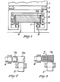
- Fig. 1 is a sectional view illustrating an example of constitution of magnetic levitation railway of this kind.
- a coach 1 is shown mounted on a truck 3 by means of a spring arrangement 2.
- the truck 3 is provided with an armature 4 of a linear induction motor (LIM) for propelling the coach, an electromagnet 5 for supporting the coach and an electromagnet 6 for guiding the coach.
- LIM linear induction motor
- a secondary iron core 8a and secondary conductor 8b of the LIM are provided opposite the armature 4 of the LIM and magnetic rails 7 used both for supporting and guiding the coach are provided on both sides of the lower surface of the track 9, with the lower surface of each rail opposed to the electromagnet 5 for levitation and the side surface of each rail opposed to the electromagnet 6 for guidance.
- the truck 3 can thus be levitated away from the track 9 by controlling current to the electromagnet 5 and guided to the right and left by controlling a magnetic force between the magnetic rail 7 and said guide electromagnet 6. Simultaneously, the coach is propelled along the track 9 by means of an electromagnetic force generated between the armature 4 and secondary conductor 8b of the LIM through control of the current in the LIM armature.
- Propulsive levitation apparatus of this kind is required to be small in size and light weight with low power consumption.
- the apparatus should ensure excellent tracking ability even over irregular stretches of track by providing the necessary electromagnetic force and electromagnetic spring constant in order to prevent contact with the track during travelling, and to save construction and running costs.
- the magnetic rail is required to exhibit small losses due to eddy currents generated by the magnetic flux from the levitation and guide electromagnets while the coach is travelling in order to save on construction and maintenance costs.
- the levitation and guide electromagnets are arranged to comprise the salient-pole type so that the N-pole and S-pole are alternately arranged along the direction of travel to meet the requirements mentioned above by minimising inductance and leakage of magnetic flux of the electromagnets, making the electromagnet light in weight and optimising the tracking ability.
- the magnetic rail is generally formed by stacking ferromagnetic plates or by combining ferromagnetic wires in order to reduce eddy current losses.
- Fig. 2 there is shown an example of propulsive levitation apparatus in the prior art, wherein a magnetic levitation rail 7a and a guide rail 7b are formed in combination, each rail being formed by stacking ferromagnetic material plates with surfaces opposed to magnetic poles, in order to suppress generation of eddy currents.
- FIG. 3 there is shown an alternative magnetic rail arrangement previously proposed.
- a magnetic levitation and guide rail 7 is formed by combining wire material 7c, consisting of insulated ferromagnetic material, in order to suppress eddy currents which might be generated in the magnetic rail 7 due to the magnetic fields generated by the electromagnets 5 and 6.
- the magnetic rail 7 employs the layered structure as shown in Fig. 2 two kinds of magnetic rails are required in different stacking directions for levitation and guidance and this results in an increase in the cost of manufacturing the magnetic rail 7.
- the structure comprising combined wire material shown in Fig. 3 has the disadvantage that a high degree of quality control is required because formation is entirely dependent on the bonding for combining the wire material. Magnetic resistance in the sectional direction becomes high because insulation is necessary between the strands of ferromagnetic material, so that the excitation current levels for the electromagnets must be raised.
- Fig. 4 there is shown a further example of propulsive levitation apparatus already proposed wherein the track is provided with a layered magnetic rail 17 formed as a layered trapezium in cross-section such that the layered side surfaces are directed downwardly in opposition to a levitation electromagnet 5 and laterally in opposition to a guide electromagnet 6 so that the magnetic rail 17 is used in common both for levitation and guidance.
- a secondary conductor 8 of the LIM is also provided, secured to both side surfaces of the track in such way that the effective surface in the LIM is vertical.
- This apparatus is intended to improve construction, installation and maintenance costs.
- the electromagnetic force of the LIM is divided into propulsive (horizontal) and vertical force components. Under ordinary running conditions, the vertical force component becomes an attractive force because sliding is minimal. Therefore, there is a further need for improvement since the vertical force component of the LIM is not used effectively.
- a rail for use in propulsive levitation apparatus for use in a magnetic levitation railway comprising a ferromagnetic core having a tapering four-sided cross-section with two non-adjacent sides being substantially mutually perpendicular and an intervening side of the cross-section providing a flattened corner portion whereby said mutually perpendicular sides can be respectively arranged opposite levitation and guide electromagnets and said flattened corner portion comprising a secondary core and secondary conductor of a linear induction motor so that an armature of the latter can be arranged opposite said flattened corner portion so as to provide both propulsion and levitation force components.
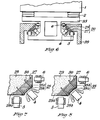
- Fig. 5 there is shown a structure of a magnetic propulsive levitation apparatus having composite magnetic rails 20 each forming a trapezium in cross-section and comprising a magnetic rail 27 consisting of a trapezium cross-section stacked iron core, in close contact with and fixed to, a magnetic rail 28 consisting of a stacked body of secondary conductor and secondary iron core forming a flattened corner portion of the rail.
- Two such composite magnetic rails are fixed, using fixing means such as bolts, to respective support portions 29a which provide downwardly inclined surfaces at both sides of the track 29.
- the trapezium cross-section of the composite magntic rail 20 is such that the mutually inclined sides are at right angles to each other and the inclined surface of the support portion 29a is at 45 degrees to the mutually inclined sides of the trapezium.
- the lower side surface of the magnetic rail is substantially horizontal while the lateral side surface of the magnetic rail is substantially vertical and accordingly the end surfaces of the ferromagnetic layers of the magnetic rail 27 are respectively located in the horizontal lower surface and vertical side surface.
- the levitation electromagnet 5 and the guide electromagnet 6 are respectively provided opposite the lower and lateral surfaces of the truck 23, the magnetic flux generated by both electromagnets enters the magnetic rail through the end surfaces of the ferromagnetic layers and forms a loop between the N-pole and S-pole in the direction of travel of the coach.
- the magnetic rail can be used both for levitation and guidance while ensuring that the magnetic flux component passing through the surfaces of the stacked layers is reduced so that magnetic resistance and eddy current losses are reduced.
- the surface of the magnetic rail 28 that is parallel to the base of the latter is inclined downward at an angle of 45 degrees to the horizontal and vertical and therefore the magnetic vertical force component of the LIM can also be used for levitation by fixing the armature 4 of the LIM to an inclined support portion 23a of truck 23 in such a way as to be opposite the surface of the rail 28 and thereby energy that would have been required for levitation can be saved.
- the section of composite magnetic rail 20 is not always required to be a trapezium with two parallel sides and it is sufficient when the horizontal lower surface and vertical lateral surface can be obtained with provision of the base to match the inclination of the support portion 29a (i.e. a trapezoidal cross-section which does not have parallel sides).
- Fig. 6 there is shown a modified form of the embodiment shown in Fig. 5.
- the only difference from the apparatus shown in Fig. 5 is that a track 39 is formed embracing truck 33 and the resulting layout of corresponding components can be easily realised by intechanging the components on the right and left hand sides of the apparatus shown in Fig. 5.
- Fig. 7 is a sectional view of a composite magnetic rail of the form used in the embodiments shown in Figs. 5 and 6.
- the common magnetic rail 27 is a so-called bonded iron core formed by ferromagnetic plates such as silicon steel plates or thin iron plates secured together with impregnation of a resin or with a bonding agent.
- the core is formed as a trapezium with the lower surface opposite the levitation electromagnet 5 and the lateral surface opposite the guide electromagnet being at right-angles to each other.
- the magnetic propulsion rail 28 consists of a layered body, for example, of the secondary iron core 28a of the LIM, consisting of a ferromagnetic plate such as a thick iron plate, and the secondary conductor 28b of the LIM, consisting of aluminium plate.
- the composite rail is arranged in close contact with the downwardly inclined surface of the support portion 29a and is fixed to the latter, for example, by means of bolts 30. It is desirable that the bolt 30 is covered with an electrical insulator in order to prevent the formation of a short-circuit.
- the influence of the protruding portion of the bolts on the gap width between the armature 4 and the secondary conductor 28b can be prevented by locating the bolts 30 outside the area that is opposite the armature 4 of the LIM, as shown in Fig. 7.
- the resulting composite magnetic rail 20 has small magnetic resistance and eddy current losses and therefore consumes relatively little energy. Moreover, since the magnetic flux generated by the armature 4 of the LIM passes through the secondary conductor 28b, proceeds through the secondary iron core 28a in the direction of travel of the coach and then returns to the armature again, the flux generates a propulsion force and a supporting lift force on the magnetic rail 29 relative to armature 4. Thus, the vertical force component of the LIM which would otherwise not be used can be used efffectively for supporting the coach.
- the secondary iron core 28a is capable of performing the function of mechanical reinforcing plate by forming said secondary iron core 28a of the LIM using a ferromagnetic plate having high mechanical intensity such as a thick iron plate and fixing the composite magnetic rail 20 to the track by means such as a through-bolt. In this way, greater reliability can be obtained than with the structures in the prior art in which mechanical strength depends on the bonding.
- Fig. 8 there is shown a sectional view of a different form of composite magnetic rail embodying the present invention with the difference from the rail shown in Fig. 7 that a secondary iron core 38 of the LIM is formed as a stacked iron core 38a having an optimum magnetic characteristic in the central area opposite the armature 4 of the LIM and on both sides of said central area the core 38 comprises thick iron plate 38b having a high mechanical strength.
- the stacked iron core 38a can be obtained by stacking the ferromagnetic plates, such a silicon steel or thick iron plates, with their intefaces at right-angles to the stacking direction of the layers of the magnetic rail 27 (and hence at right-angles to the flattened corner portion of the rail provided by the secondary conductor 28b) and then mutually fixing the ferromagnetic plates by means of impregnation of a resin or using a bonding agent.
- the magnetic flux generated by the armature 4 passes through the secondary conductor 28b and proceeds through the secondary iron core in the direction of travel along the layers. Accordingly, reduction of eddy current losses due to the stacking can be expected and since the iron plate 38b functions as a mechanical reinforcement member, a composite magnetic rail having high mechanical reliability can be obtained.
- the composite magnetic rails described above as embodiments of this invention can thus provide levitation, guidance and propulsion. As a result the costs of rail manufacture, track construction and maintenance can be reduced as compared with known arrangements. Moreover, since both the lower surface opposite the levitation electromagnet and the lateral surface opposite the guide electromagnet are formed as common end surfaces of the ferromagnetic plates of the stack, the magnetic flux of both electromagnets passes through the magnetic rail along the stacked layers and the magnetic flux component across the stacked layers is lower than that of conventional structures. Accordingly, eddy current losses and magnetic resistance can be reduced and the power to be consumed for levitation and guidance can also be lowered.
- the excitation power of the levitation electromagnet can be reduced and since the function of the secondary iron core as a reinforcing member of the composite magnetic rail can be achieved by forming the secondary core of the linear induction motor as a thick iron plate, a more reliable magnetic rail than conventional structures dependent on the integrity of adhesive bonding, can be obtained.
- a rail for use in propulsive levitation apparatus for use in a magnetic levitation railway comprising a ferromagnetic core having a tapering four-sided cross-section with two non-adjacent sides being substantially mutually perpendicular and an intervening side of the cross-section providing a flattened corner portion whereby said mutually perpendicular sides can be respectively arranged opposite levitation and guide electromagnets 5 and 6 and said flattened corner portion comprising a secondary core 28a and secondary conductor 28b of a linear induction motor so that an armature of the latter can be arranged opposite said flattened corner portion so as to provide both propulsion and levitation force components.
- the rails described above as embodying this invention each has a cross-section substantially in the form of a trapezium (a quadrilateral with only two sides parallel)
- the cross-section may be trapezoidal (quadrilateral with no sides parallel) or may comprise a side opposite the flattened corner portion that is convex outwards to allow the stacked ferromagnetic plates to be curved, e.g. circular in cross-section so that the interfaces between the stacked plates can be at right-angles to the lower and lateral surfaces and so aligned with the lines of flux entering from the levitation and guide electromagnets.
- the track support portions then need to be concave to receive the convex surfaces of the rails.
Landscapes
- Engineering & Computer Science (AREA)
- Physics & Mathematics (AREA)
- Electromagnetism (AREA)
- Power Engineering (AREA)
- Transportation (AREA)
- Mechanical Engineering (AREA)
- Control Of Vehicles With Linear Motors And Vehicles That Are Magnetically Levitated (AREA)
- Linear Motors (AREA)
Priority Applications (1)
| Application Number | Priority Date | Filing Date | Title |
|---|---|---|---|
| EP85307720A EP0224617A1 (de) | 1985-10-25 | 1985-10-25 | Schiene zur Anwendung bei einer magnetischen Trag- und Vortriebsvorrichtung |
Applications Claiming Priority (1)
| Application Number | Priority Date | Filing Date | Title |
|---|---|---|---|
| EP85307720A EP0224617A1 (de) | 1985-10-25 | 1985-10-25 | Schiene zur Anwendung bei einer magnetischen Trag- und Vortriebsvorrichtung |
Publications (1)
| Publication Number | Publication Date |
|---|---|
| EP0224617A1 true EP0224617A1 (de) | 1987-06-10 |
Family
ID=8194415
Family Applications (1)
| Application Number | Title | Priority Date | Filing Date |
|---|---|---|---|
| EP85307720A Withdrawn EP0224617A1 (de) | 1985-10-25 | 1985-10-25 | Schiene zur Anwendung bei einer magnetischen Trag- und Vortriebsvorrichtung |
Country Status (1)
| Country | Link |
|---|---|
| EP (1) | EP0224617A1 (de) |
Cited By (8)
| Publication number | Priority date | Publication date | Assignee | Title |
|---|---|---|---|---|
| DE4023067A1 (de) * | 1990-07-20 | 1992-01-23 | Weh Herbert | Magnetschwebetechnik in kombination mit dem asynchronen linearantrieb |
| EP0487744A4 (en) * | 1990-06-20 | 1992-12-02 | Kabushiki Kaisha Yaskawa Denki Seisakusho | Underwater linear transport system |
| DE19948490A1 (de) * | 1999-10-07 | 2001-05-31 | Univ Hannover | Lineardirektantrieb |
| EP1925071A4 (de) * | 2005-08-22 | 2010-12-08 | Dumitru Bojiuc | Magnetisch schwebendes transportsystem |
| CN102874261A (zh) * | 2012-10-09 | 2013-01-16 | 莱芜美澳冶金科技有限公司 | 一种直线电机列车行走机构 |
| CN111725969A (zh) * | 2020-07-24 | 2020-09-29 | 苏州英磁新能源科技有限公司 | 磁悬浮导向的无槽有铁芯平板直线电机 |
| CN112208347A (zh) * | 2019-10-09 | 2021-01-12 | 大连奇想科技有限公司 | 电磁悬浮列车轨道系统及悬浮电磁铁 |
| WO2024216808A1 (zh) * | 2023-04-17 | 2024-10-24 | 中车长春轨道客车股份有限公司 | 一种永磁电动悬浮系统及磁浮列车制式结构 |
Citations (1)
| Publication number | Priority date | Publication date | Assignee | Title |
|---|---|---|---|---|
| EP0144000A2 (de) * | 1983-11-04 | 1985-06-12 | Fuji Electric Corporate Research And Development Ltd. | Schwebevorrichtung für Schwebefahrzeug mit magnetischer Anziehung |
-
1985
- 1985-10-25 EP EP85307720A patent/EP0224617A1/de not_active Withdrawn
Patent Citations (1)
| Publication number | Priority date | Publication date | Assignee | Title |
|---|---|---|---|---|
| EP0144000A2 (de) * | 1983-11-04 | 1985-06-12 | Fuji Electric Corporate Research And Development Ltd. | Schwebevorrichtung für Schwebefahrzeug mit magnetischer Anziehung |
Cited By (13)
| Publication number | Priority date | Publication date | Assignee | Title |
|---|---|---|---|---|
| EP0487744A4 (en) * | 1990-06-20 | 1992-12-02 | Kabushiki Kaisha Yaskawa Denki Seisakusho | Underwater linear transport system |
| DE4023067A1 (de) * | 1990-07-20 | 1992-01-23 | Weh Herbert | Magnetschwebetechnik in kombination mit dem asynchronen linearantrieb |
| DE19948490A1 (de) * | 1999-10-07 | 2001-05-31 | Univ Hannover | Lineardirektantrieb |
| DE19948490C2 (de) * | 1999-10-07 | 2003-05-15 | Univ Hannover | Lineardirektantrieb |
| EP1925071A4 (de) * | 2005-08-22 | 2010-12-08 | Dumitru Bojiuc | Magnetisch schwebendes transportsystem |
| CN102874261B (zh) * | 2012-10-09 | 2015-08-26 | 莱芜美澳冶金科技有限公司 | 一种直线电机列车行走机构 |
| CN102874261A (zh) * | 2012-10-09 | 2013-01-16 | 莱芜美澳冶金科技有限公司 | 一种直线电机列车行走机构 |
| CN112208347A (zh) * | 2019-10-09 | 2021-01-12 | 大连奇想科技有限公司 | 电磁悬浮列车轨道系统及悬浮电磁铁 |
| CN112421990A (zh) * | 2019-10-09 | 2021-02-26 | 大连奇想科技有限公司 | 电磁悬浮列车轨道系统 |
| EP4105058A4 (de) * | 2019-10-09 | 2024-05-01 | Dalian Whim Science & Technology Limited Company | Elektromagnetisches schwebebahnsystem und schwebeelektromagnet |
| CN111725969A (zh) * | 2020-07-24 | 2020-09-29 | 苏州英磁新能源科技有限公司 | 磁悬浮导向的无槽有铁芯平板直线电机 |
| CN111725969B (zh) * | 2020-07-24 | 2025-09-05 | 苏州英磁新能源科技有限公司 | 磁悬浮导向的无槽有铁芯平板直线电机 |
| WO2024216808A1 (zh) * | 2023-04-17 | 2024-10-24 | 中车长春轨道客车股份有限公司 | 一种永磁电动悬浮系统及磁浮列车制式结构 |
Similar Documents
| Publication | Publication Date | Title |
|---|---|---|
| EP0144000B1 (de) | Schwebevorrichtung für Schwebefahrzeug mit magnetischer Anziehung | |
| US6758146B2 (en) | Laminated track design for inductrack maglev systems | |
| US6633217B2 (en) | Inductrack magnet configuration | |
| US6664880B2 (en) | Inductrack magnet configuration | |
| US7096794B2 (en) | Inductrack configuration | |
| US6827022B2 (en) | Magnetic levitation and propulsion system | |
| US3884154A (en) | Propulsion arrangement equipped with a linear motor | |
| WO2023241361A1 (zh) | 一种永磁电动悬浮系统及其导向方法 | |
| JP3920358B2 (ja) | 磁気浮上車両の走行システム | |
| CN121201117A (zh) | 电磁悬浮列车轨道系统 | |
| US3841227A (en) | Suspension system for a magnetic suspension railroad | |
| GB1441818A (en) | Tries ltd linear motor electromagnetic rails | |
| US20180030662A1 (en) | Rail-bound maglev train | |
| WO2019143469A1 (en) | Permanent magnet magnet maglev using passive, lo-frequency electromagnetic stabilization | |
| JPH01177805A (ja) | 吸引形磁気浮上車 | |
| US3850108A (en) | Armature assembly and magnetically suspended vehicle | |
| JPH11122718A (ja) | 磁気浮上式鉄道用推進・浮上・案内用地上コイル、磁気浮上式鉄道用推進・浮上・案内用地上コイルの接続方法、磁気浮上式鉄道の支持・案内用構造物、磁気浮上式鉄道の支持・案内用構造物の施工方法、磁気浮上式鉄道の推進・浮上・案内装置、磁気浮上式鉄道の推進・浮上・案内方法、磁気浮上式鉄道システム、磁気浮上式鉄道の集電システム、及び磁気浮上式鉄道の集電方法 | |
| US3967561A (en) | Linear-induction motor especially for high-speed suspension vehicles | |
| EP0222938A1 (de) | Schiene zur Anwendung bei einer magnetischen Trag- und Vortriebsvorrichtung | |
| JP5009138B2 (ja) | 磁気浮上機構 | |
| US4510421A (en) | Linear magnet | |
| KR20220015203A (ko) | 널플럭스 자기부상 장치 및 시스템 | |
| CN115189545A (zh) | 悬浮与导向自稳定的增强型直线感应电机 | |
| JPS60229664A (ja) | 吸引形磁気浮上式鉄道の磁気浮上推進装置 | |
| CN118056703A (zh) | 磁悬浮电磁推进一体化装置 |
Legal Events
| Date | Code | Title | Description |
|---|---|---|---|
| PUAI | Public reference made under article 153(3) epc to a published international application that has entered the european phase |
Free format text: ORIGINAL CODE: 0009012 |
|
| AK | Designated contracting states |
Kind code of ref document: A1 Designated state(s): DE FR GB |
|
| STAA | Information on the status of an ep patent application or granted ep patent |
Free format text: STATUS: THE APPLICATION IS DEEMED TO BE WITHDRAWN |
|
| 18D | Application deemed to be withdrawn |
Effective date: 19871211 |
|
| RIN1 | Information on inventor provided before grant (corrected) |
Inventor name: YAMAGUCHI, HITOSHI Inventor name: YAMAMURA, SAKAE |