EP0224652A1 - Fördervorrichtung für die Werkstücke bei einer Mehrstufenpresse - Google Patents
Fördervorrichtung für die Werkstücke bei einer Mehrstufenpresse Download PDFInfo
- Publication number
- EP0224652A1 EP0224652A1 EP86111404A EP86111404A EP0224652A1 EP 0224652 A1 EP0224652 A1 EP 0224652A1 EP 86111404 A EP86111404 A EP 86111404A EP 86111404 A EP86111404 A EP 86111404A EP 0224652 A1 EP0224652 A1 EP 0224652A1
- Authority
- EP
- European Patent Office
- Prior art keywords
- feed
- driving apparatus
- rod
- feed bar
- feed screw
- Prior art date
- Legal status (The legal status is an assumption and is not a legal conclusion. Google has not performed a legal analysis and makes no representation as to the accuracy of the status listed.)
- Granted
Links
- 230000033001 locomotion Effects 0.000 claims abstract description 24
- 238000010276 construction Methods 0.000 description 2
- 230000005540 biological transmission Effects 0.000 description 1
- 230000000694 effects Effects 0.000 description 1
Images



Classifications
-
- B—PERFORMING OPERATIONS; TRANSPORTING
- B30—PRESSES
- B30B—PRESSES IN GENERAL
- B30B15/00—Details of, or accessories for, presses; Auxiliary measures in connection with pressing
-
- B—PERFORMING OPERATIONS; TRANSPORTING
- B21—MECHANICAL METAL-WORKING WITHOUT ESSENTIALLY REMOVING MATERIAL; PUNCHING METAL
- B21D—WORKING OR PROCESSING OF SHEET METAL OR METAL TUBES, RODS OR PROFILES WITHOUT ESSENTIALLY REMOVING MATERIAL; PUNCHING METAL
- B21D43/00—Feeding, positioning or storing devices combined with, or arranged in, or specially adapted for use in connection with, apparatus for working or processing sheet metal, metal tubes or metal profiles; Associations therewith of cutting devices
- B21D43/02—Advancing work in relation to the stroke of the die or tool
- B21D43/04—Advancing work in relation to the stroke of the die or tool by means in mechanical engagement with the work
- B21D43/05—Advancing work in relation to the stroke of the die or tool by means in mechanical engagement with the work specially adapted for multi-stage presses
- B21D43/055—Devices comprising a pair of longitudinally and laterally movable parallel transfer bars
-
- B—PERFORMING OPERATIONS; TRANSPORTING
- B21—MECHANICAL METAL-WORKING WITHOUT ESSENTIALLY REMOVING MATERIAL; PUNCHING METAL
- B21D—WORKING OR PROCESSING OF SHEET METAL OR METAL TUBES, RODS OR PROFILES WITHOUT ESSENTIALLY REMOVING MATERIAL; PUNCHING METAL
- B21D43/00—Feeding, positioning or storing devices combined with, or arranged in, or specially adapted for use in connection with, apparatus for working or processing sheet metal, metal tubes or metal profiles; Associations therewith of cutting devices
- B21D43/02—Advancing work in relation to the stroke of the die or tool
- B21D43/04—Advancing work in relation to the stroke of the die or tool by means in mechanical engagement with the work
- B21D43/05—Advancing work in relation to the stroke of the die or tool by means in mechanical engagement with the work specially adapted for multi-stage presses
-
- B—PERFORMING OPERATIONS; TRANSPORTING
- B30—PRESSES
- B30B—PRESSES IN GENERAL
- B30B1/00—Presses, using a press ram, characterised by the features of the drive therefor, pressure being transmitted directly, or through simple thrust or tension members only, to the press ram or platen
- B30B1/24—Presses, using a press ram, characterised by the features of the drive therefor, pressure being transmitted directly, or through simple thrust or tension members only, to the press ram or platen by rack-and-pinion means
-
- Y—GENERAL TAGGING OF NEW TECHNOLOGICAL DEVELOPMENTS; GENERAL TAGGING OF CROSS-SECTIONAL TECHNOLOGIES SPANNING OVER SEVERAL SECTIONS OF THE IPC; TECHNICAL SUBJECTS COVERED BY FORMER USPC CROSS-REFERENCE ART COLLECTIONS [XRACs] AND DIGESTS
- Y10—TECHNICAL SUBJECTS COVERED BY FORMER USPC
- Y10T—TECHNICAL SUBJECTS COVERED BY FORMER US CLASSIFICATION
- Y10T74/00—Machine element or mechanism
- Y10T74/16—Alternating-motion driven device with means during operation to adjust stroke
- Y10T74/1625—Stroke adjustable to zero and/or reversible in phasing
- Y10T74/165—Driving lever with adjustable pivot point
Definitions
- the height of the rod-driving cam provided on the slide must be changed or the clamp drive mechanism must be changed, in order to change the feed bar clamp and/or lift stroke length.
- the apparatus cannot change its stroke length once it is manufactured.
- the latter type apparatus adopts a mechanism of changing a fulcrum position of the lever, but with change in said position, both swinging ends of the lever will be changed. Consequently, the internal width between the feed bars needs to be adjusted every time the clamp stroke is changed.
- adjusting operation becomes complicated in case that the transfer device is independently and manually operated and that programming becomes also complicated in case of automatic adjustment.
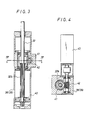
- the present invention comprises a lever having a cam follower at one end thereof and connected to the rod at the other end, said lever being formed with a longitudinal opening in the central portion thereof, a fulcrum member slidably housed in the opening of the lever, and a link having an axis for rotation at one end thereof with the other end facing the fulcrum member, said facing portion being connected with a pin provided at the center of the fulcrum member, said opening of the lever being formed in an arc corresponding to the locus of the pin when the link rotates with the lever at either limit of its swinging motion, said rod being connected at the lower end thereof to the clamp unit, and said cam follower of the lever being in contact with a cam rotated in association with a crankshaft, wherein the present apparatus is selectively used when the clamp and/or lift stroke is adjusted.
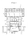
- Fig. 1 is a schematic front view of a press 1 having a crown 2 and a bed 3 joined together by columns 4 and 4, inside which a press slide 5 is provided and is lifted and lowered with relative to a bolster 6 provided on the bed 3.
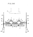
- the feed screw rod 14 and the spline rod 15 are respectively provided with helical or worm gears 30 and 31 at one end protruding from the unit casing 9.
- the worm gears 30 and 31 are respectively engaged with worms 32a and 32b of vertical screw rods 32 and 33.
- the upper ends of the vertical screw rods 32 and 33 are respectively connected via ball joints 34 and 35 to vertical rods 36 and 37.
- the vertical rods 36 and 37 are adapted to move up and down in association with the press drive system.
- the clamp cylinders 38 and 39 are respectively provided at the lower ends of the vertical rods 36 and 37, as shown in Fig. 2A, ensuring contact between the corresponding cam follower 57 and the cam 56.
- the upper ends of the vertical rods are respectively connected to adjustment cylinders 70 and 70 each for separating the cam 56 from the lever 50 and moving only the vertical rod up and down.
Landscapes
- Engineering & Computer Science (AREA)
- Mechanical Engineering (AREA)
- Press Drives And Press Lines (AREA)
- Transmission Devices (AREA)
Priority Applications (1)
| Application Number | Priority Date | Filing Date | Title |
|---|---|---|---|
| AT86111404T ATE50173T1 (de) | 1985-09-09 | 1986-08-18 | Foerdervorrichtung fuer die werkstuecke bei einer mehrstufenpresse. |
Applications Claiming Priority (6)
| Application Number | Priority Date | Filing Date | Title |
|---|---|---|---|
| JP137735/85U | 1985-09-09 | ||
| JP13773585U JPH0233944Y2 (de) | 1985-09-09 | 1985-09-09 | |
| JP154225/85U | 1985-10-08 | ||
| JP1985154225U JPS6267621U (de) | 1985-10-08 | 1985-10-08 | |
| JP26912/86U | 1986-02-25 | ||
| JP1986026912U JPS62137632U (de) | 1986-02-25 | 1986-02-25 |
Publications (2)
| Publication Number | Publication Date |
|---|---|
| EP0224652A1 true EP0224652A1 (de) | 1987-06-10 |
| EP0224652B1 EP0224652B1 (de) | 1990-02-07 |
Family
ID=27285590
Family Applications (1)
| Application Number | Title | Priority Date | Filing Date |
|---|---|---|---|
| EP86111404A Expired - Lifetime EP0224652B1 (de) | 1985-09-09 | 1986-08-18 | Fördervorrichtung für die Werkstücke bei einer Mehrstufenpresse |
Country Status (5)
| Country | Link |
|---|---|
| US (1) | US4741195A (de) |
| EP (1) | EP0224652B1 (de) |
| KR (1) | KR900005908B1 (de) |
| CA (1) | CA1267376A (de) |
| DE (1) | DE3668805D1 (de) |
Cited By (7)
| Publication number | Priority date | Publication date | Assignee | Title |
|---|---|---|---|---|
| US4929164A (en) * | 1987-10-22 | 1990-05-29 | Norda S.P.A. Via Vallecamonica | Compound press for piece molding |
| EP0578928A1 (de) * | 1992-07-16 | 1994-01-19 | Günter Zierpka | Vorschubeinrichtung zum schrittweisen Material- und/oder Werkstücktransport an bzw. in intermittierend arbeitenden Produktionsmaschinen |
| EP0650781A3 (de) * | 1993-10-28 | 1995-06-07 | Maschinenfabrik Müller-Weingarten AG | Antriebseinrichtung für einen mehrachsigen Transport von Werkstücken in einer Transferpresse |
| EP0701872A1 (de) * | 1994-08-13 | 1996-03-20 | SCHULER PRESSEN GmbH & Co. | Einrichtung zum dreidimensionalen Antrieb von Greiferschienen |
| CN109261805A (zh) * | 2018-12-01 | 2019-01-25 | 罗峰 | 一种便于定位的冲压模具 |
| CN109604403A (zh) * | 2018-11-30 | 2019-04-12 | 重庆程顺汽车配件制造有限公司 | 一种用于汽车零部件的冲压装置及其使用方法 |
| CN111036786A (zh) * | 2019-12-28 | 2020-04-21 | 青岛瑞巨鑫机械配件加工有限公司 | 一种自动化多功能机械配件加工装置 |
Families Citing this family (13)
| Publication number | Priority date | Publication date | Assignee | Title |
|---|---|---|---|---|
| DE3905069C2 (de) * | 1989-02-18 | 2000-10-12 | Schuler Pressen Gmbh & Co | Pressen-Anlage mit mehreren Pressen zum Bearbeiten von Blechteilen |
| US5136874A (en) * | 1989-11-06 | 1992-08-11 | Rapindex Incorporated | Indexing conveyor for a die transfer system |
| DE4117101A1 (de) * | 1991-05-25 | 1992-11-26 | Schuler Gmbh L | Einrichtung zur aenderung des hebelverhaeltnisses eines zweiarmigen schwinghebels |
| DE4237313A1 (de) * | 1992-11-05 | 1994-05-11 | Schuler Gmbh L | Presse mit einer Umsetzeinrichtung für Blechteile |
| DE4331479A1 (de) * | 1993-09-16 | 1995-03-23 | Guenter Zierpka | Vorschubeinrichtung zum schrittweisen Material- und/oder Werkstücktransport an bzw. in intermittierend arbeitenden Produktionsmaschinen |
| US5749290A (en) * | 1996-09-20 | 1998-05-12 | Johnson; Lawrence A. | Press transfer apparatus |
| TW422773B (en) * | 1997-05-28 | 2001-02-21 | Apic Yamada Corp | Electric press machine |
| DE19740293A1 (de) * | 1997-09-13 | 1999-03-18 | Schuler Pressen Gmbh & Co | Transferpressen mit automatischem Toolingwechsel |
| JP3773405B2 (ja) * | 2000-09-29 | 2006-05-10 | アイダエンジニアリング株式会社 | トランスファ装置 |
| SE527214C2 (sv) * | 2004-06-01 | 2006-01-24 | Flexlink Components Ab | Arrangemang och metod för räckesinställning vid en transportör |
| CN109226558A (zh) * | 2018-10-24 | 2019-01-18 | 温州阿德沃自动化设备有限公司 | 一种送料装置 |
| CN114289660B (zh) * | 2021-12-29 | 2023-11-14 | 蓝山县鸿坤金属制品有限公司 | 一种可移动式锻造件加工镦粗设备 |
| CN117901471B (zh) * | 2024-03-20 | 2024-05-14 | 济南恒拓液压机械有限公司 | 一种液压机械挤压成型设备 |
Citations (4)
| Publication number | Priority date | Publication date | Assignee | Title |
|---|---|---|---|---|
| DE1802630B2 (de) * | 1967-10-16 | 1975-04-10 | Verson Allsteel Press Co., Chicago, Ill. (V.St.A.) | Vorrichtung zum überführen von Werkstücken zwischen aufeinanderfolgenden Bearbeitungsstationen an Pressen u. dgl. Werkzeugmaschinen |
| DE2359912A1 (de) * | 1973-11-29 | 1975-06-12 | Hitachi Shipbuilding Eng Co | Vorschubstangenantriebsvorrichtung fuer eine transfer-presse |
| FR2278615A1 (fr) * | 1974-07-15 | 1976-02-13 | Gulf & Western Mfg Co | Dispositif de reglage micrometrique et de controle par lecture directe du mecanisme d'amenage a rouleaux d'une presse |
| US4393682A (en) * | 1981-03-06 | 1983-07-19 | Aida Engineering, Ltd. | Feed bar driving apparatus for a transfer press |
Family Cites Families (5)
| Publication number | Priority date | Publication date | Assignee | Title |
|---|---|---|---|---|
| US605282A (en) * | 1898-06-07 | Steam-valve for locomotives or other en | ||
| US3411636A (en) * | 1966-04-12 | 1968-11-19 | Bernard J. Wallis | Transfer device |
| US4607516A (en) * | 1982-09-03 | 1986-08-26 | Danly Machine Corporation | Transfer feed press with improved transfer feed system |
| US4651866A (en) * | 1985-01-17 | 1987-03-24 | Aida Engineering, Ltd. | Feed bar driving system in transfer press machine |
| US4630461A (en) * | 1985-05-17 | 1986-12-23 | Avondale Industries, Inc. | Transfer feed mechanism for power presses |
-
1986
- 1986-08-18 DE DE8686111404T patent/DE3668805D1/de not_active Expired - Fee Related
- 1986-08-18 EP EP86111404A patent/EP0224652B1/de not_active Expired - Lifetime
- 1986-08-19 CA CA000516316A patent/CA1267376A/en not_active Expired - Fee Related
- 1986-09-06 KR KR1019860007425A patent/KR900005908B1/ko not_active Expired
- 1986-09-09 US US06/905,326 patent/US4741195A/en not_active Expired - Fee Related
Patent Citations (4)
| Publication number | Priority date | Publication date | Assignee | Title |
|---|---|---|---|---|
| DE1802630B2 (de) * | 1967-10-16 | 1975-04-10 | Verson Allsteel Press Co., Chicago, Ill. (V.St.A.) | Vorrichtung zum überführen von Werkstücken zwischen aufeinanderfolgenden Bearbeitungsstationen an Pressen u. dgl. Werkzeugmaschinen |
| DE2359912A1 (de) * | 1973-11-29 | 1975-06-12 | Hitachi Shipbuilding Eng Co | Vorschubstangenantriebsvorrichtung fuer eine transfer-presse |
| FR2278615A1 (fr) * | 1974-07-15 | 1976-02-13 | Gulf & Western Mfg Co | Dispositif de reglage micrometrique et de controle par lecture directe du mecanisme d'amenage a rouleaux d'une presse |
| US4393682A (en) * | 1981-03-06 | 1983-07-19 | Aida Engineering, Ltd. | Feed bar driving apparatus for a transfer press |
Cited By (9)
| Publication number | Priority date | Publication date | Assignee | Title |
|---|---|---|---|---|
| US4929164A (en) * | 1987-10-22 | 1990-05-29 | Norda S.P.A. Via Vallecamonica | Compound press for piece molding |
| EP0578928A1 (de) * | 1992-07-16 | 1994-01-19 | Günter Zierpka | Vorschubeinrichtung zum schrittweisen Material- und/oder Werkstücktransport an bzw. in intermittierend arbeitenden Produktionsmaschinen |
| EP0650781A3 (de) * | 1993-10-28 | 1995-06-07 | Maschinenfabrik Müller-Weingarten AG | Antriebseinrichtung für einen mehrachsigen Transport von Werkstücken in einer Transferpresse |
| EP0701872A1 (de) * | 1994-08-13 | 1996-03-20 | SCHULER PRESSEN GmbH & Co. | Einrichtung zum dreidimensionalen Antrieb von Greiferschienen |
| US5779025A (en) * | 1994-08-13 | 1998-07-14 | Schuler Pressen Gmbh & Co. | Three-dimensional gripper rail drive apparatus |
| CN109604403A (zh) * | 2018-11-30 | 2019-04-12 | 重庆程顺汽车配件制造有限公司 | 一种用于汽车零部件的冲压装置及其使用方法 |
| CN109261805A (zh) * | 2018-12-01 | 2019-01-25 | 罗峰 | 一种便于定位的冲压模具 |
| CN109261805B (zh) * | 2018-12-01 | 2020-07-17 | 唐山宏利工具制造有限公司 | 一种便于定位的冲压模具 |
| CN111036786A (zh) * | 2019-12-28 | 2020-04-21 | 青岛瑞巨鑫机械配件加工有限公司 | 一种自动化多功能机械配件加工装置 |
Also Published As
| Publication number | Publication date |
|---|---|
| KR870002940A (ko) | 1987-04-14 |
| CA1267376A (en) | 1990-04-03 |
| US4741195A (en) | 1988-05-03 |
| KR900005908B1 (ko) | 1990-08-16 |
| DE3668805D1 (de) | 1990-03-15 |
| EP0224652B1 (de) | 1990-02-07 |
Similar Documents
| Publication | Publication Date | Title |
|---|---|---|
| EP0224652B1 (de) | Fördervorrichtung für die Werkstücke bei einer Mehrstufenpresse | |
| EP0315381B1 (de) | Transfervorrichtung für Transferpressen | |
| DE3245317C2 (de) | ||
| DE10259814B4 (de) | Werkstücküberführungs-Verfahren und Werkstücküberführungs-Einrichtung für Reihen-Pressenstraße | |
| GB2165478A (en) | Tapping machine | |
| EP0685276B1 (de) | Umsetzvorrichtung in einer Umformmaschine, insbesondere einer Transferpresse | |
| JPH0785819B2 (ja) | 鍛造プレスの自動搬送装置 | |
| US4311429A (en) | Workpiece transfer mechanism | |
| US4244668A (en) | Apparatus for forming internal teeth at large workpieces at a gear shaper | |
| US4728253A (en) | Apparatus for advancing and returning feed bars for a transfer press | |
| JPH0614906Y2 (ja) | トランスファプレスのリフトダウン装置 | |
| US3888104A (en) | Forging machine | |
| GB2051637A (en) | Rotary multi-station press | |
| US4651866A (en) | Feed bar driving system in transfer press machine | |
| JPH0242349Y2 (de) | ||
| US6109423A (en) | Feed stroke changing device for transfer feeder | |
| RU2041001C1 (ru) | Автоматическая линия для штамповки крупногабаритных деталей | |
| CN216263295U (zh) | 一种精密机械加工用多工位锻压效果好的液压机 | |
| JPH0221151Y2 (de) | ||
| CN220311384U (zh) | 一种下动式数控折弯机三轴后挡料 | |
| CN220838269U (zh) | 一种滚齿机工作台 | |
| JPH0147252B2 (de) | ||
| JPH022505Y2 (de) | ||
| JPS647002Y2 (de) | ||
| SU1741603A3 (ru) | Устройство дл привода подающей линейки дл многопозиционного пресса |
Legal Events
| Date | Code | Title | Description |
|---|---|---|---|
| PUAI | Public reference made under article 153(3) epc to a published international application that has entered the european phase |
Free format text: ORIGINAL CODE: 0009012 |
|
| AK | Designated contracting states |
Kind code of ref document: A1 Designated state(s): AT BE CH DE FR GB IT LI LU NL SE |
|
| 17P | Request for examination filed |
Effective date: 19870708 |
|
| 17Q | First examination report despatched |
Effective date: 19880822 |
|
| GRAA | (expected) grant |
Free format text: ORIGINAL CODE: 0009210 |
|
| ITF | It: translation for a ep patent filed | ||
| AK | Designated contracting states |
Kind code of ref document: B1 Designated state(s): AT BE CH DE FR GB IT LI LU NL SE |
|
| REF | Corresponds to: |
Ref document number: 50173 Country of ref document: AT Date of ref document: 19900215 Kind code of ref document: T |
|
| ET | Fr: translation filed | ||
| REF | Corresponds to: |
Ref document number: 3668805 Country of ref document: DE Date of ref document: 19900315 |
|
| PG25 | Lapsed in a contracting state [announced via postgrant information from national office to epo] |
Ref country code: AT Effective date: 19900818 |
|
| PG25 | Lapsed in a contracting state [announced via postgrant information from national office to epo] |
Ref country code: SE Effective date: 19900819 |
|
| PG25 | Lapsed in a contracting state [announced via postgrant information from national office to epo] |
Ref country code: LU Free format text: LAPSE BECAUSE OF NON-PAYMENT OF DUE FEES Effective date: 19900831 Ref country code: LI Effective date: 19900831 Ref country code: CH Effective date: 19900831 Ref country code: BE Effective date: 19900831 |
|
| PLBE | No opposition filed within time limit |
Free format text: ORIGINAL CODE: 0009261 |
|
| STAA | Information on the status of an ep patent application or granted ep patent |
Free format text: STATUS: NO OPPOSITION FILED WITHIN TIME LIMIT |
|
| BECN | Be: change of holder's name |
Effective date: 19900207 |
|
| 26N | No opposition filed | ||
| BERE | Be: lapsed |
Owner name: AIDA ENGINEERING LTD Effective date: 19900831 |
|
| PG25 | Lapsed in a contracting state [announced via postgrant information from national office to epo] |
Ref country code: NL Effective date: 19910301 |
|
| NLV4 | Nl: lapsed or anulled due to non-payment of the annual fee | ||
| PG25 | Lapsed in a contracting state [announced via postgrant information from national office to epo] |
Ref country code: FR Effective date: 19910430 |
|
| REG | Reference to a national code |
Ref country code: CH Ref legal event code: PL |
|
| REG | Reference to a national code |
Ref country code: FR Ref legal event code: ST |
|
| PGFP | Annual fee paid to national office [announced via postgrant information from national office to epo] |
Ref country code: DE Payment date: 19920527 Year of fee payment: 9 |
|
| PGFP | Annual fee paid to national office [announced via postgrant information from national office to epo] |
Ref country code: GB Payment date: 19920807 Year of fee payment: 7 |
|
| PG25 | Lapsed in a contracting state [announced via postgrant information from national office to epo] |
Ref country code: GB Effective date: 19930818 |
|
| GBPC | Gb: european patent ceased through non-payment of renewal fee |
Effective date: 19930818 |
|
| EUG | Se: european patent has lapsed |
Ref document number: 86111404.9 Effective date: 19910410 |
|
| PG25 | Lapsed in a contracting state [announced via postgrant information from national office to epo] |
Ref country code: DE Effective date: 19960501 |
|
| PG25 | Lapsed in a contracting state [announced via postgrant information from national office to epo] |
Ref country code: IT Free format text: LAPSE BECAUSE OF NON-PAYMENT OF DUE FEES Effective date: 20050818 |