EP0224672A1 - Verfahren zum Entfernen insbesondere von keramischer Gussformen von Gussteilen - Google Patents
Verfahren zum Entfernen insbesondere von keramischer Gussformen von Gussteilen Download PDFInfo
- Publication number
- EP0224672A1 EP0224672A1 EP86113407A EP86113407A EP0224672A1 EP 0224672 A1 EP0224672 A1 EP 0224672A1 EP 86113407 A EP86113407 A EP 86113407A EP 86113407 A EP86113407 A EP 86113407A EP 0224672 A1 EP0224672 A1 EP 0224672A1
- Authority
- EP
- European Patent Office
- Prior art keywords
- casting
- mold
- shock waves
- liquid
- castings
- Prior art date
- Legal status (The legal status is an assumption and is not a legal conclusion. Google has not performed a legal analysis and makes no representation as to the accuracy of the status listed.)
- Granted
Links
- 238000005266 casting Methods 0.000 title claims abstract description 21
- 238000000034 method Methods 0.000 title claims description 16
- 239000000919 ceramic Substances 0.000 title claims description 6
- 230000035939 shock Effects 0.000 claims abstract description 20
- 239000007788 liquid Substances 0.000 claims description 9
- 238000001816 cooling Methods 0.000 claims description 2
- 239000002360 explosive Substances 0.000 claims 1
- 238000007711 solidification Methods 0.000 claims 1
- 230000008023 solidification Effects 0.000 claims 1
- 238000005516 engineering process Methods 0.000 abstract description 5
- 239000011162 core material Substances 0.000 description 11
- XLYOFNOQVPJJNP-UHFFFAOYSA-N water Substances O XLYOFNOQVPJJNP-UHFFFAOYSA-N 0.000 description 6
- 238000005495 investment casting Methods 0.000 description 4
- 238000004140 cleaning Methods 0.000 description 2
- 150000001875 compounds Chemical class 0.000 description 2
- 239000000463 material Substances 0.000 description 2
- 239000012778 molding material Substances 0.000 description 2
- 238000000465 moulding Methods 0.000 description 2
- 239000003921 oil Substances 0.000 description 2
- 229910001060 Gray iron Inorganic materials 0.000 description 1
- 230000008878 coupling Effects 0.000 description 1
- 238000010168 coupling process Methods 0.000 description 1
- 238000005859 coupling reaction Methods 0.000 description 1
- 230000001419 dependent effect Effects 0.000 description 1
- 230000000694 effects Effects 0.000 description 1
- 239000012634 fragment Substances 0.000 description 1
- 239000011344 liquid material Substances 0.000 description 1
- 229910052751 metal Inorganic materials 0.000 description 1
- 239000002184 metal Substances 0.000 description 1
- 150000002739 metals Chemical class 0.000 description 1
- 239000004576 sand Substances 0.000 description 1
- 238000007790 scraping Methods 0.000 description 1
- 238000000527 sonication Methods 0.000 description 1
- 239000000126 substance Substances 0.000 description 1
- 239000000725 suspension Substances 0.000 description 1
- 230000001960 triggered effect Effects 0.000 description 1
Images
Classifications
-
- B—PERFORMING OPERATIONS; TRANSPORTING
- B22—CASTING; POWDER METALLURGY
- B22D—CASTING OF METALS; CASTING OF OTHER SUBSTANCES BY THE SAME PROCESSES OR DEVICES
- B22D29/00—Removing castings from moulds, not restricted to casting processes covered by a single main group; Removing cores; Handling ingots
- B22D29/001—Removing cores
- B22D29/007—Removing cores by using explosive shock waves
- B22D29/008—Removing cores by using explosive shock waves in a liquid medium
Definitions
- the invention relates to a method and devices for carrying out the method for detaching, in particular, ceramic molds and / or cores of cast parts.
- Investment casting technology is a widespread technique for producing machine parts and tools of almost any shape from metals.
- the liquid material is given and solidified into workpiece-specific shapes made of special ceramics.
- the ceramic molding compound is completely detached from the workpiece in several operations by knocking off the molding compound, sand and / or water jet cleaning and chemical cleaning. If the smallest molded parts or parts of a cast core remain in corners, recesses or cavities of the investment casting workpiece, this can have a disadvantageous effect on the use, for example with regard to the service life of the workpiece.
- the invention has for its object to provide a method and an apparatus for performing the method with which molded parts or core parts can be easily and completely removed from castings.
- This object is achieved in that according to the Solidify and cool the mold is introduced into a liquid, for example water, and the mold, cast part and core are sonicated with shock waves, as a result of which the mold material and the core material are completely detached from the cast part.
- a liquid for example water
- shock waves brittle materials can be broken up into the smallest fragments, so that a workpiece can be completely freed from the mold and the cores by introducing a series of shock waves.
- the workpiece has orders of magnitude higher compressive strength and tensile strength than the molding material and the core materials. For this reason, the shock wave does not change the workpiece.
- the surface finish of the workpieces and the accuracy of the workpiece dimensions, to which high demands are made in investment casting technology remain unchanged due to the sonication using shock waves, while mechanical influences (e.g. scraping) almost damage the surface and thus also result in a loss of accuracy are inevitable. For this reason, the process is particularly advantageous for investment casting technology. With other casting techniques - e.g. Gray cast iron technology - the application of the method is conceivable, but because of the lower demands on surface quality and accuracy in relation to the usual foundry, it can hardly be used economically.
- Focused shock waves are preferably used for the gentle removal of the molding material and core material, a fixed focus generally being present in a liquid bath (oil or water) and the casting mold is tracked using a device in a water bath, so that all parts can be sonicated according to a sound system plan.
- the casting mold with casting is located in the case of complicated workpieces, rotatable in gimbal suspension on a table within the water bath that can be moved in three degrees of freedom.
- Computer-controlled, rotary and translatory actuators can move every point of the workpiece into focus and stay in focus for a shorter or longer time.
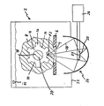
- the single figure shows a cross-sectional view through a device for the treatment of castings by means of shock waves.
- a mold 8 which contains a cast part 10, is located in a tub 2 on a table 6 provided with a recess 4.
- the cast part is a cylindrical ring 12 which has a plurality of projections 16 extending beyond its jacket 14.
- a core 20 which, like the mold 4, is to be removed.
- a reflector 24 which is part of an ellipsoid of revolution.
- a spark gap 25 which is operated by means of a spark generator 26, is arranged in the focus F1 of the reflector becomes.
- a spark is triggered, a mechanical shock wave is generated, the duration of which is 500 nanoseconds to 1 microsecond.
- the shock wave takes the course outlined by lines 28 and reaches focus F2 directly or after reflection on the wall of the ellipsoid of revolution.
- pressure surges of, for example, 1000 to 2000 bar occur, which cause the mold 8 to flake off from the cast part 10.
- both the mold 8 and the core 20 are separated from the cast part 10 without any remnants of the molded part or core sticking to the cast part and its surface quality and accuracy being unaffected. So that the shock waves can reach the workpiece and the second focus, the trough 2 and the reflector are filled with a liquid and there is a recess 4 in the table 6. The better the acoustic impedance (product of the density ⁇ and the speed of sound c) of the liquid and the Mold 8 match, the more effectively the shock waves reach the focus F2. Oils are preferably proposed as the coupling liquid, but the device can also be operated and functions in a water bath.
Landscapes
- Engineering & Computer Science (AREA)
- Mechanical Engineering (AREA)
- Molds, Cores, And Manufacturing Methods Thereof (AREA)
- Apparatuses For Generation Of Mechanical Vibrations (AREA)
- Moulds For Moulding Plastics Or The Like (AREA)
Abstract
Description
- Die Erfindung betrifft ein Verfahren und Einrichtungen zur Durchführung des Verfahrens zum Ablösen insbesondere keramischen Gussformen und/oder Kernen von Gussteilen.
- Eine weitverbreitete Technik zur Herstellung von nahezu beliebig geformten Maschinenteilen und Werkzeugen aus Metallen ist die Feingusstechnik. Dazu wird der flüssige Werkstoff in werkstückspezifische Formen aus speziellen Keramiken gegeben und erstarrt. Nach dem Erkalten wird in mehreren Arbeitsgängen durch Abschlagen der Formmasse, Sand und/oder Wasserstrahlreinigung, chemische Reinigung die keramische Formmasse vollständig vom Werkstück gelöst. Verbleiben kleinste Formteile oder Teile eines Gusskerns in Ecken, Vertiefungen oder Hohlräumen des Feingusswerkstücks, so kann sich dies nachteilig auf die Verwendung, zum Beispiel hinsichtlich der Lebensdauer des Werkstücks auswirken.
- Der Erfindung liegt die Aufgabe zugrunde, ein Verfahren und eine Vorrichtung zur Durchführung des Verfahrens zu schaffen, mit dem Formteile oder Kernteile mühelos und restlos von Gussteilen entfernt werden können.
- Diese Aufgabe wird erfindungsgemäss dadurch gelöst, dass nach dem Erstarren und Abkühlen die Form mit dem Gussteil in eine Flüssigkeit, zum Beispiel Wasser, eingebracht wird und Form, Gussteil und Kern mit Stosswellen beschallt werden, wodurch der Gussformwerkstoff und der Kernwerkstoff vollständig vom Gussteil abgelöst werden.
- Mittels Stosswellen lassen sich spröde Werkstoffe in kleinste Fragmente zertrümmern, sodass ein Werkstück durch die Einleitung einer Folge von Stosswellen völlig von der Gussform und den Kernen befreit werden kann. Das Werkstück besitzt um Grössenordnungen höhere Druckfestigkeit und Zugfestigkeit als das Formmaterial und die Kernwerkstoffe. Aus diesem Grund tritt eine Veränderung des Werkstücks durch die Stosswelle nicht auf. Das Oberflächenfinish der Werkstücke und die Genauigkeit der Werkstückabmessungen, an die in der Feingusstechnik hohe Anforderungen gestellt werden, bleiben durch die Beschallung mittels Stosswellen unverändert erhalten, während bei mechanischen Einwirkungen (z. B. Abkratzen) eine Verletzung der Oberfläche und damit auch ein Genauigkeitsverlust nahezu unvermeidlich sind. Aus diesem Grund ist das Verfahren auch besonders für die Feingusstechnik vorteilhaft. Bei anderen Gusstechniken - z.B. Graugusstechnik - ist die Anwendung des Verfahrens zwar denkbar, jedoch wegen geringerer Anforderungen an Oberflächengüte und Genauigkeit im Verhältnis zur üblichen Gussputzerei kaum wirtschaftlich einsetzbar.
- Vorzugsweise werden fokussierte Stosswellen zum schonenden Entfernen des Formmaterials und Kernmaterials verwendet, wobei in der Regel in einem Flüssigkeitsbad (Öl oder Wasser) ein ortsfester Fokus vorhanden ist und die Gussform mittels einer Vorrichtung im Wasserbad nachgeführt wird, sodass alle Teile entsprechend einem Beschallungsplan beschallt werden können. Dazu befindet sich die Gussform mit Gussteil bei komplizierten Werkstücken drehbar in kardanischer Aufhängung auf einem in den drei Freiheitsgraden beweglichen Tisch innerhalb des Wasserbads. Computergesteuert kann mittels rotatorisch und translatorisch arbeitender Stellmotoren jeder Punkt des Werkstücks in den Fokus gefahren werden und kürzer oder länger im Fokus verweilen.
- Vorteilhafte Ausgestaltungen der Erfindung sind Gegenstand von Unteransprüchen.
- Die Erfindung wird nachfolgend anhand einer Figur näher erläutert.
- Die einzige Figur zeigt eine Querschnittsansicht durch ein Gerät zur Behandlung von Gussteilen mittels Stosswellen.
In einer Wanne 2 befindet sich auf einem mit einer Aussparung 4 versehenen Tisch 6 eine Gussform 8, die ein Gussteil 10 enthält. Das Gussteil ist im Ausführungsbeispiel ein zylinderförmiger Ring 12, der mehrere über seinen Mantel 14 hinausreichende Vorsprünge 16 aufweist. In der Bohrung 18 des Zylinders 12 befindet sich ein Kern 20, der wie auch die Gussform 4 entfernt werden soll. - Am Boden 22 der Wanne 2 befindet sich ein Reflektor 24, der ein Teil eines Rotationsellipsoids ist. Im Fokus F1 des Reflektors ist eine Funkenstrecke 25 angeordnet, die mittels eines Funkengenerators 26 betrieben wird. Beim Auslösen eines Funkens entsteht eine mechanische Stosswelle, deren Dauer 500 Nanosekunden bis 1 Mikrosekunde beträgt. Die Stosswelle nimmt den durch die Linien 28 skizzierten Verlauf und gelangt direkt oder nach Reflektion an der Wand des Rotationsellipsoids zum Fokus F2. Im Fokus F2 treten Druckstösse von beispielsweise 1000 bis 2000 bar auf, die ein Abplatzen der Gussform 8 vom Gussteil 10 bewirken. Durch eine serielle Auslösung von Stosswellen und Nachführung der Grenzflächen des Bauteils in den Fokus werden sowohl Gussform 8 wie auch Kern 20 vom Gussteil 10 getrennt, ohne dass irgendwelche Reste des Formteils oder Kerns am Gussteil haften bleiben und dessen Oberflächengüte und Genauigkeit unbeeinflusst bleibt.
Damit die Stosswellen zum Werkstück und zweiten Fokus gelangen können sind die Wanne 2 und der Reflektor mit einer Flüssigkeit gefüllt und im Tisch 6 befindet sich eine Aussparung 4. Je besser akustische Impedanz (Produkt aus der Dichte ρ und der Schallgeschwindigkeit c) der Flüssigkeit und der Gussform 8 übereinstimmen, umso effektiver gelangen die Stosswellen zum Fokus F2. Als Koppelflüssigkeit werden vorzugsweise Öle vorgeschlagen, jedoch ist die Einrichtung auch im Wasserbad betreibbar und funktionsfähig.
Claims (8)
Applications Claiming Priority (2)
| Application Number | Priority Date | Filing Date | Title |
|---|---|---|---|
| DE3543062 | 1985-12-05 | ||
| DE3543062A DE3543062C1 (de) | 1985-12-05 | 1985-12-05 | Verfahren und Vorrichtung zum Entfernen insbesondere keramischer Gussformen von Gussteilen mittels Stosswellen |
Publications (2)
| Publication Number | Publication Date |
|---|---|
| EP0224672A1 true EP0224672A1 (de) | 1987-06-10 |
| EP0224672B1 EP0224672B1 (de) | 1990-01-31 |
Family
ID=6287746
Family Applications (1)
| Application Number | Title | Priority Date | Filing Date |
|---|---|---|---|
| EP86113407A Expired - Lifetime EP0224672B1 (de) | 1985-12-05 | 1986-09-30 | Verfahren zum Entfernen insbesondere von keramischer Gussformen von Gussteilen |
Country Status (4)
| Country | Link |
|---|---|
| US (1) | US4802525A (de) |
| EP (1) | EP0224672B1 (de) |
| JP (1) | JPS62134164A (de) |
| DE (1) | DE3543062C1 (de) |
Cited By (1)
| Publication number | Priority date | Publication date | Assignee | Title |
|---|---|---|---|---|
| GB2248569A (en) * | 1990-10-11 | 1992-04-15 | Copper Peel Jones Prod | Making a casting using a frangible core |
Families Citing this family (20)
| Publication number | Priority date | Publication date | Assignee | Title |
|---|---|---|---|---|
| US7189209B1 (en) * | 1996-03-29 | 2007-03-13 | Sanuwave, Inc. | Method for using acoustic shock waves in the treatment of a diabetic foot ulcer or a pressure sore |
| US6390995B1 (en) | 1997-02-12 | 2002-05-21 | Healthtronics Surgical Services, Inc. | Method for using acoustic shock waves in the treatment of medical conditions |
| US7275582B2 (en) * | 1999-07-29 | 2007-10-02 | Consolidated Engineering Company, Inc. | Methods and apparatus for heat treatment and sand removal for castings |
| US6655234B2 (en) * | 2000-01-31 | 2003-12-02 | Baker Hughes Incorporated | Method of manufacturing PDC cutter with chambers or passages |
| RU2186656C2 (ru) * | 2000-03-24 | 2002-08-10 | Комсомольский-на-Амуре государственный технический университет | Способ выбивки отливки из разовой литейной формы |
| US6622775B2 (en) * | 2000-05-10 | 2003-09-23 | Consolidated Engineering Company, Inc. | Method and apparatus for assisting removal of sand moldings from castings |
| CA2422646C (en) * | 2000-07-27 | 2008-01-29 | Consolidated Engineering Company, Inc. | Method and apparatus for assisting removal of sand moldings from castings |
| MXPA03006906A (es) * | 2001-02-02 | 2004-01-29 | Cons Eng Co Inc | Equipo integrado para el procesamiento de metal. |
| FR2831086B1 (fr) * | 2001-10-19 | 2004-02-06 | Peugeot Citroen Automobiles Sa | Procede de fabrication par coulee de pieces metalliques comportant au moins une partie formee par noyautage et utilisation |
| US7216691B2 (en) * | 2002-07-09 | 2007-05-15 | Alotech Ltd. Llc | Mold-removal casting method and apparatus |
| JP2005532911A (ja) * | 2002-07-11 | 2005-11-04 | コンソリデイテッド エンジニアリング カンパニー, インコーポレイテッド | 鋳造物からの砂鋳型の除去を補助するための方法および装置 |
| US7165600B2 (en) * | 2002-09-11 | 2007-01-23 | Alotech Ltd. Llc | Chemically bonded aggregate mold |
| US7121318B2 (en) * | 2002-09-20 | 2006-10-17 | Alotech Ltd. Llc | Lost pattern mold removal casting method and apparatus |
| AU2003272624A1 (en) * | 2002-09-20 | 2004-04-08 | Alotech Ltd. Llc | Lost pattern mold removal casting method and apparatus |
| JP4903696B2 (ja) * | 2004-06-28 | 2012-03-28 | コンソリデイテッド エンジニアリング カンパニー, インコーポレイテッド | 鋳造物からばりおよび閉塞片を除去するための方法および装置 |
| US20060054294A1 (en) * | 2004-09-15 | 2006-03-16 | Crafton Scott P | Short cycle casting processing |
| US20060103059A1 (en) * | 2004-10-29 | 2006-05-18 | Crafton Scott P | High pressure heat treatment system |
| US7493965B1 (en) | 2006-04-12 | 2009-02-24 | Us Synthetic Corporation | Apparatuses and methods relating to cooling a subterranean drill bit and/or at least one cutting element during use |
| MX2008015525A (es) * | 2006-06-15 | 2009-01-07 | Cons Eng Co Inc | Metodos y sistema para fabricar piezas fundidas utilizando un sistema de fabricacion flexible, automatizado. |
| WO2008121671A2 (en) * | 2007-03-29 | 2008-10-09 | Consolidated Engineering Company, Inc. | Vertical heat treatment system |
Citations (5)
| Publication number | Priority date | Publication date | Assignee | Title |
|---|---|---|---|---|
| US3030678A (en) * | 1959-09-08 | 1962-04-24 | Sr William J Huston | Method of disintegrating a sand mold while in association with a flask and a casting |
| DE1962182A1 (de) * | 1968-12-13 | 1970-08-27 | Wakamatsu Sharyo K K | Verfahren zum Ausschuetteln von Gussstuecken |
| DE2141174A1 (de) * | 1971-08-17 | 1973-03-01 | Pk Bjuro Elektrogidrawliki Gos | Anlage zum ausschlagen der kerne aus gusstuecken |
| US4374538A (en) * | 1980-05-16 | 1983-02-22 | Robert Bosch Gmbh | Apparatus for decoring and explosive treatment of materials |
| US4490180A (en) * | 1982-04-13 | 1984-12-25 | Proektno-Konstruktorskoe Bjuro Elektrogidravliki Akademii Nauk Ukrainskoi Ssr | Method for electrohydroblasting of castings |
Family Cites Families (3)
| Publication number | Priority date | Publication date | Assignee | Title |
|---|---|---|---|---|
| DE234811C (de) * | ||||
| SU440862A1 (ru) * | 1971-09-20 | 1978-03-30 | Проектно-конструкторское бюро электрогидравлики | Установка дл электрогидравлической очистки |
| DD234811A1 (de) * | 1985-03-01 | 1986-04-16 | Schwermasch Liebknecht Veb K | Einrichtung zum entfernen anhaftender formstoffreste am gussstueck |
-
1985
- 1985-12-05 DE DE3543062A patent/DE3543062C1/de not_active Expired
-
1986
- 1986-09-30 EP EP86113407A patent/EP0224672B1/de not_active Expired - Lifetime
- 1986-11-04 JP JP61262601A patent/JPS62134164A/ja active Pending
- 1986-12-05 US US06/938,571 patent/US4802525A/en not_active Expired - Fee Related
Patent Citations (5)
| Publication number | Priority date | Publication date | Assignee | Title |
|---|---|---|---|---|
| US3030678A (en) * | 1959-09-08 | 1962-04-24 | Sr William J Huston | Method of disintegrating a sand mold while in association with a flask and a casting |
| DE1962182A1 (de) * | 1968-12-13 | 1970-08-27 | Wakamatsu Sharyo K K | Verfahren zum Ausschuetteln von Gussstuecken |
| DE2141174A1 (de) * | 1971-08-17 | 1973-03-01 | Pk Bjuro Elektrogidrawliki Gos | Anlage zum ausschlagen der kerne aus gusstuecken |
| US4374538A (en) * | 1980-05-16 | 1983-02-22 | Robert Bosch Gmbh | Apparatus for decoring and explosive treatment of materials |
| US4490180A (en) * | 1982-04-13 | 1984-12-25 | Proektno-Konstruktorskoe Bjuro Elektrogidravliki Akademii Nauk Ukrainskoi Ssr | Method for electrohydroblasting of castings |
Non-Patent Citations (1)
| Title |
|---|
| GIESSEREI, Band 55, Nr. 9, 25. April 1968, Seiten 198-202, Düsseldorf, DE; VON LÜBOMIC RAFAILOW et al.: "Elektrohydraulisches Putzen von Gussstücken" * |
Cited By (3)
| Publication number | Priority date | Publication date | Assignee | Title |
|---|---|---|---|---|
| GB2248569A (en) * | 1990-10-11 | 1992-04-15 | Copper Peel Jones Prod | Making a casting using a frangible core |
| WO1993021349A1 (en) * | 1990-10-11 | 1993-10-28 | Peel Jones Copper Products Limited | Castings |
| GB2248569B (en) * | 1990-10-11 | 1994-12-21 | Copper Peel Jones Prod | Cast consumable furnace components |
Also Published As
| Publication number | Publication date |
|---|---|
| DE3543062C1 (de) | 1987-05-14 |
| EP0224672B1 (de) | 1990-01-31 |
| US4802525A (en) | 1989-02-07 |
| JPS62134164A (ja) | 1987-06-17 |
Similar Documents
| Publication | Publication Date | Title |
|---|---|---|
| DE3543062C1 (de) | Verfahren und Vorrichtung zum Entfernen insbesondere keramischer Gussformen von Gussteilen mittels Stosswellen | |
| EP0304683B1 (de) | Verfahren und Vorrichtung zum Entkernen von Gussstücken | |
| DE60300436T2 (de) | Verfahren zur Herstellung von Einsätzen für dampfgekühlte und heissem Gasfluss ausgesetze Komponenten | |
| DE3637367A1 (de) | Einrichtung zum entfernen des kernsandes aus guss-stuecken | |
| DE3118640A1 (de) | Vorrichtung zur oberflaechenbearbeitung von leichtbauwabenkoerpern | |
| EP0054276A1 (de) | Verfahren zum Herstellen von aus synthetischem Beton bestehenden Maschinenteilen sowie diese Maschinenteile, insbesondere Maschinenständer für Werkzeugmaschinen | |
| DE69327714T2 (de) | Feingiessverfahren zur Herstellung von Gussstücken | |
| DE19925674B4 (de) | Kennzeichnung von Gußteilen | |
| DE4040573A1 (de) | Verfahren zum behandeln von form- und/oder kernsand | |
| DE2758350A1 (de) | Verfahren und vorrichtung zur behandlung der schmelze von metallen und metallegierungen mittels makroschalls | |
| AT520370B1 (de) | Verfahren zur Herstellung eines gegossenen Werkstückes | |
| DE3320309C2 (de) | Verfahren zur Herstellung von Präzisionsmeßformen, Gießformen und deren Verwendung | |
| DE2222246C3 (de) | Verfahren zum Entfernen der Speiser von PräzisionsguBstücken | |
| DE741438C (de) | Verfahren zum Herstellen metallischer UEberzuege auf metallischen Werkstuecken | |
| DE4418363C2 (de) | Verfahren zum Füllen von Formen mit fließfähigen Modell- und Formmassen | |
| DE921402C (de) | Vorrichtung zum elektro-induktiven Schweissen von Schlitzrohren | |
| CH653407A5 (de) | Verbindungsstange fuer einen radialkolbenmotor und verfahren zum herstellen derselben. | |
| DE2654167C3 (de) | Verfahren zum Entgraten von Sandkernen für die Gießereitechnik | |
| DE948856C (de) | Verfahren und Vorrichtung zur Herstellung von an ihrer Oberflaeche mit einem Mantelblech aus oxydierbarem Material versehenen basischen, feuerfesten Steinen | |
| DE10204055A1 (de) | Verfahren zur Aufbereitung von Sand für Gussformteile | |
| DD240156A1 (de) | Verfahren zum entfernen von form- und kernsandmassen von gussstuecken | |
| DE1951974C (de) | Raumwerkzeug zum Entfernen von Anguß und Steigeransatzen und zum Entgraten von Gußeisen Senenstucken | |
| DE19851435B4 (de) | Reinigung von Gießereiformwerkzeugen | |
| DE2103261A1 (en) | Etching or pickling metals or synthetic resins - using ultrasonic vibrations | |
| SU923718A1 (ru) | Способ удаления керамической формы или стержня из технологической оснастки 1 |
Legal Events
| Date | Code | Title | Description |
|---|---|---|---|
| PUAI | Public reference made under article 153(3) epc to a published international application that has entered the european phase |
Free format text: ORIGINAL CODE: 0009012 |
|
| AK | Designated contracting states |
Kind code of ref document: A1 Designated state(s): FR GB IT NL SE |
|
| 17P | Request for examination filed |
Effective date: 19870523 |
|
| 17Q | First examination report despatched |
Effective date: 19880503 |
|
| GRAA | (expected) grant |
Free format text: ORIGINAL CODE: 0009210 |
|
| AK | Designated contracting states |
Kind code of ref document: B1 Designated state(s): FR GB IT NL SE |
|
| PG25 | Lapsed in a contracting state [announced via postgrant information from national office to epo] |
Ref country code: IT Free format text: LAPSE BECAUSE OF FAILURE TO SUBMIT A TRANSLATION OF THE DESCRIPTION OR TO PAY THE FEE WITHIN THE PRESCRIBED TIME-LIMIT;WARNING: LAPSES OF ITALIAN PATENTS WITH EFFECTIVE DATE BEFORE 2007 MAY HAVE OCCURRED AT ANY TIME BEFORE 2007. THE CORRECT EFFECTIVE DATE MAY BE DIFFERENT FROM THE ONE RECORDED. Effective date: 19900131 Ref country code: FR Effective date: 19900131 Ref country code: NL Effective date: 19900131 Ref country code: SE Effective date: 19900131 Ref country code: GB Effective date: 19900131 |
|
| EN | Fr: translation not filed | ||
| NLV1 | Nl: lapsed or annulled due to failure to fulfill the requirements of art. 29p and 29m of the patents act | ||
| GBV | Gb: ep patent (uk) treated as always having been void in accordance with gb section 77(7)/1977 [no translation filed] | ||
| PLBE | No opposition filed within time limit |
Free format text: ORIGINAL CODE: 0009261 |
|
| STAA | Information on the status of an ep patent application or granted ep patent |
Free format text: STATUS: NO OPPOSITION FILED WITHIN TIME LIMIT |
|
| 26N | No opposition filed |