EP0224708A2 - Dents pour une machine pour travailler le sol - Google Patents
Dents pour une machine pour travailler le sol Download PDFInfo
- Publication number
- EP0224708A2 EP0224708A2 EP86114825A EP86114825A EP0224708A2 EP 0224708 A2 EP0224708 A2 EP 0224708A2 EP 86114825 A EP86114825 A EP 86114825A EP 86114825 A EP86114825 A EP 86114825A EP 0224708 A2 EP0224708 A2 EP 0224708A2
- Authority
- EP
- European Patent Office
- Prior art keywords
- tines
- tillage
- tine
- markings
- tillage part
- Prior art date
- Legal status (The legal status is an assumption and is not a legal conclusion. Google has not performed a legal analysis and makes no representation as to the accuracy of the status listed.)
- Granted
Links
Images


Classifications
-
- A—HUMAN NECESSITIES
- A01—AGRICULTURE; FORESTRY; ANIMAL HUSBANDRY; HUNTING; TRAPPING; FISHING
- A01B—SOIL WORKING IN AGRICULTURE OR FORESTRY; PARTS, DETAILS, OR ACCESSORIES OF AGRICULTURAL MACHINES OR IMPLEMENTS, IN GENERAL
- A01B23/00—Elements, tools, or details of harrows
- A01B23/02—Teeth; Fixing the teeth
-
- A—HUMAN NECESSITIES
- A01—AGRICULTURE; FORESTRY; ANIMAL HUSBANDRY; HUNTING; TRAPPING; FISHING
- A01B—SOIL WORKING IN AGRICULTURE OR FORESTRY; PARTS, DETAILS, OR ACCESSORIES OF AGRICULTURAL MACHINES OR IMPLEMENTS, IN GENERAL
- A01B33/00—Tilling implements with rotary driven tools, e.g. in combination with fertiliser distributors or seeders, with grubbing chains, with sloping axles, with driven discs
- A01B33/08—Tools; Details, e.g. adaptations of transmissions or gearings
- A01B33/10—Structural or functional features of the tools ; Theoretical aspects of the cutting action
- A01B33/106—Structural or functional features of the tools ; Theoretical aspects of the cutting action the rotating shaft being oriented vertically or steeply inclined
-
- A—HUMAN NECESSITIES
- A01—AGRICULTURE; FORESTRY; ANIMAL HUSBANDRY; HUNTING; TRAPPING; FISHING
- A01B—SOIL WORKING IN AGRICULTURE OR FORESTRY; PARTS, DETAILS, OR ACCESSORIES OF AGRICULTURAL MACHINES OR IMPLEMENTS, IN GENERAL
- A01B33/00—Tilling implements with rotary driven tools, e.g. in combination with fertiliser distributors or seeders, with grubbing chains, with sloping axles, with driven discs
- A01B33/08—Tools; Details, e.g. adaptations of transmissions or gearings
- A01B33/14—Attaching the tools to the rotating shaft, e.g. resiliently or flexibly-attached tools
- A01B33/146—Attaching the tools to the rotating shaft, e.g. resiliently or flexibly-attached tools the rotating shaft being oriented vertically or steeply inclined
Definitions
- the invention relates to a tine for a tillage machine according to the preambles of claims 1 and 3.
- Such a tine is already known from German utility model 82 13 540.
- This tine has a knife-like edge on its side facing the direction of rotation.
- the advantage of this tine is that it is elastic. Due to its design as a leaf spring, the tine can deflect to the side and against its direction of rotation by a limited amount if the tine hits a stone. This prevents damage to the tines and the tillage machine.
- the invention is based on the object of substantially improving the known tines for use on straw-rich soils or to provide a simple possibility for the replacement of worn tillage tines.
- this object is achieved in that the tillage part is rounded on the side facing its direction of rotation and wider than on the side facing away from its direction of rotation.
- self-cleaning of the tine is achieved, at least in its lower part, when the tillage machine is used to stubble up stubble fields.
- this tine does not collect the straw and no straw settles on the tilling part of the tine that works in the ground, but rather the straw pushes up on this relatively wide tilling part of the tine and then falls above the ground surface due to the forward movement of the tillage machine and the rotating movement of the tine from the tines.
- self-cleaning of the tines is achieved when used on straw-rich soils. This effect is all the more surprising since tines with relatively narrow front sides, as in the known tines, pull the straw very much together and that the straw practically sticks to these tines.
- the tine has an approximately triangular cross-section with rounded corners in the area of its tillage part.
- this cross-sectional shape, in which one surface of the triangular cross-section has the working surface that faces the direction of rotation of the tine is, proven to be advantageous.
- Another solution to the problem is achieved in that after wear and tear of the tillage part on the remaining tines a new tillage part can be welded, that the tine has markings below its attachment point and above the tillage part, which determine the weld point of the new tillage part.
- a practically new tine is created in the simplest and most cost-effective manner after the wear and tear on the tillage part. Due to the markings that determine the welding point of the new tillage part on the old fastening part of the tine, the farmer himself can weld a new tillage part on the remaining tines. The farmer then only has to create a clean welding point along the markings using an angle grinder or other cutting device.
- the new tillage parts can also be welded to the remaining tines exactly in the desired manner and in the desired position. So that the longest possible weld seam is obtained, the invention provides that the markings run obliquely to the longitudinal axis of the tine.
- the tillage machine has the frame 1, in which the tool rotors 2 are arranged next to one another in a row running transversely to the direction of travel.
- the tool rotors 2 are driven by the PTO shaft of the tractor pulling the tillage machine, but not shown, the respectively adjacent tool rotors 2 in the rotate in opposite directions about upright axes.
- the tool rotors 2 have a plate-shaped design.
- the tines 3 projecting downward are fastened to these tool rotors 2.
- the side plate 4, which limits the displacement of the earth to the outside, is arranged laterally next to the respective outer tool rotors 2.
- the trailing roller 5 is arranged with its teeth 6 arranged on the circumference.
- the tool rotors 2 have receiving openings 7 pointing radially outwards for the respective fastening parts 8 of the tines 3.
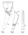
- the tines 3 each have the tillage part 9 which works the soil and a fastening part 8 which is angled approximately at right angles to the tillage part 9.
- This fastening part 8 has the two bores 10. These bores 10 have a corresponding position to bores in the tool rotors 2, so that the tines 3 are secured by the holes in the tool rotors 2 and the tines.
- the tine 3 has a width B on the side 12 facing its direction of rotation 11, which is greater than the width b on the side 13 of the soil treatment part 9 of the tine 3 facing away from the direction of rotation 11. Furthermore, the processing part 9 faces its direction of rotation 11 Page 12 rounded.
- the tine 9 has in the area of its tillage part 9 an approximately triangular cross section 14 with the rounded corners 15. Due to the wide surface of the tillage part 9 of the tine 3 on its side 12 facing the direction of rotation 11, a very good crumbling effect of the soil is achieved by crushing the impact, and additionally a good mixing is achieved by the tillage part 9 of the tine 3 standing on the handle effect of the soil is achieved. This is achieved primarily by the good shovel action of the wide tillage part 9.
- the tine 3 has the markings formed as elevations 16 above its tillage part 9. These markings 16 determine the welding point 17 of a new tillage part 18, as shown in FIGS. 5 and 6.
- the tillage part 9 of the tine 3 is worn approximately to the markings 16, the remaining tine 19, as shown in FIG. 5, which essentially consists of the fastening part 8 and the upper angled part of the tine 3, is preferably also used an angle grinder or other cutting device along the line drawn by the elevations 16, the remaining upper part of the tillage part 9 is cut off, so that a straight weld line is obtained which corresponds to the slope 20 on the new tillage part 18, so that the new tillage part 18 occupies the same position as the original machining part 9 on the prongs 3.
- the new tillage part 18 has bevelled edges 20 on its inclined upper side, so that a sufficiently thick weld seam 21 is obtained. After welding the new machining part 18, which is indicated in FIG. 4 with dash-dotted lines, a practically new tine is obtained again. New Tillage parts 18 can be welded several times to a residual tine 19.
- the markings 19, which determine the course of the weld seam run at an angle ⁇ of less than 60 ° to the vertical, based on the assembly of the tine 3 on the Tool spinning top 2.
- the knife tine 22 is also provided for mounting on the tool rotors 2 of the tillage machine shown in FIG. 1. These knife tines 22 have a trailing cutting edge 23. The cutting edge 23 is located on the tillage part 24 of the knife tine 22. Furthermore, the tine 22 has a fastening part 8 which is angled approximately at right angles to the tillage part 24. The tine 22 has, above its tillage part, the markings formed as impressions 25, which mark the welding point of a new tillage part 26 shown in FIGS. 10 and 11.
- an angle grinder or another separating device along the markings 25 creates a straight cut surface which runs obliquely to the longitudinal axis of the tine, so that the new tillage part at this cut surface by means of the weld seam 27 26, which is shown in broken lines in Fig. 9, can be welded.
- the tillage tines 22 can be renewed again and again in a simple and cost-effective manner by the farmer in the simplest way using the least possible material.
Landscapes
- Life Sciences & Earth Sciences (AREA)
- Engineering & Computer Science (AREA)
- Mechanical Engineering (AREA)
- Soil Sciences (AREA)
- Environmental Sciences (AREA)
- Soil Working Implements (AREA)
Applications Claiming Priority (2)
| Application Number | Priority Date | Filing Date | Title |
|---|---|---|---|
| DE3538895 | 1985-11-02 | ||
| DE19853538895 DE3538895A1 (de) | 1985-11-02 | 1985-11-02 | Zinken fuer eine bodenbearbeitungsmaschine |
Publications (3)
| Publication Number | Publication Date |
|---|---|
| EP0224708A2 true EP0224708A2 (fr) | 1987-06-10 |
| EP0224708A3 EP0224708A3 (en) | 1989-04-12 |
| EP0224708B1 EP0224708B1 (fr) | 1991-08-07 |
Family
ID=6285005
Family Applications (1)
| Application Number | Title | Priority Date | Filing Date |
|---|---|---|---|
| EP86114825A Expired - Lifetime EP0224708B1 (fr) | 1985-11-02 | 1986-10-24 | Dents pour une machine pour travailler le sol |
Country Status (2)
| Country | Link |
|---|---|
| EP (1) | EP0224708B1 (fr) |
| DE (2) | DE3538895A1 (fr) |
Families Citing this family (1)
| Publication number | Priority date | Publication date | Assignee | Title |
|---|---|---|---|---|
| DK178763B1 (en) * | 2015-11-07 | 2017-01-09 | Kongskilde Ind As | A sieve and a device for stone picking stones from soil |
Family Cites Families (5)
| Publication number | Priority date | Publication date | Assignee | Title |
|---|---|---|---|---|
| DE8213540U1 (de) * | 1982-05-11 | 1982-08-19 | Rabewerk Heinrich Clausing, 4515 Bad Essen | Kreiselegge mit mehreren Werkzeugkreiseln |
| NL177644C (nl) * | 1974-01-10 | 1985-11-01 | Lely Nv C Van Der | Tand voor een grondbewerkingsmachine. |
| DE2835634C2 (de) * | 1978-08-14 | 1986-04-03 | H. Niemeyer Söhne GmbH & Co KG, 4446 Hörstel | Maschine zur Bodenbearbeitung |
| NL7810716A (nl) * | 1978-10-27 | 1980-04-29 | Patent Concern Nv | Grondbewerkingsmachine. |
| AU522527B2 (en) * | 1980-06-20 | 1982-06-10 | Farm Innovations Pty. Ltd. | Agricultural shares |
-
1985
- 1985-11-02 DE DE19853538895 patent/DE3538895A1/de not_active Withdrawn
-
1986
- 1986-10-24 DE DE8686114825T patent/DE3680759D1/de not_active Expired - Lifetime
- 1986-10-24 EP EP86114825A patent/EP0224708B1/fr not_active Expired - Lifetime
Also Published As
| Publication number | Publication date |
|---|---|
| DE3680759D1 (de) | 1991-09-12 |
| EP0224708B1 (fr) | 1991-08-07 |
| DE3538895A1 (de) | 1987-05-07 |
| EP0224708A3 (en) | 1989-04-12 |
Similar Documents
| Publication | Publication Date | Title |
|---|---|---|
| EP3753383B1 (fr) | Élément de coupe | |
| CH629648A5 (de) | Bodenbearbeitungsgeraet. | |
| DE1457690A1 (de) | Garten- und Ackerbaugeraet | |
| DE2950916A1 (de) | Drehbares messer fuer grasmaeher | |
| EP0150731A2 (fr) | Outil à main de jardinage pour l'ameublissement du sol | |
| DE1204448B (de) | Rotierendes Schlegelmesser | |
| DE2839601C3 (de) | Bodenbearbeitungsmaschine | |
| DE2613676A1 (de) | Bodenbearbeitungsmaschine | |
| DE2728656B2 (de) | Erdbearbeitungswerkzeug für Sämaschinen | |
| DE2226093A1 (de) | Rasenmäher | |
| EP0224708B1 (fr) | Dents pour une machine pour travailler le sol | |
| CH648724A5 (de) | Vorrichtung zur bodenbearbeitung, insbesondere fuer garten- oder parkanlagen. | |
| EP0260643A2 (fr) | Couteau pour un cultivateur de gazon | |
| DE10153964A1 (de) | Bodenbearbeitungsgerät zum Einebnen, Zerkleinern und Rückverfestigen des Bodens | |
| DE2833399A1 (de) | Kreiselgrubber | |
| DE3151842C2 (fr) | ||
| DE3127064C2 (fr) | ||
| DE2849868C3 (de) | Bodenbearbeitungsmaschine | |
| DE2750106C2 (de) | Bodenbearbeitungsmaschine | |
| DE8030612U1 (de) | Gerät zum Auflockern und Zerkleinern von verdichteten Bodenschichten | |
| DE396550C (de) | Geraet zur Moorkultur | |
| DE7820611U1 (de) | Bodenbearbeitungsmaschine | |
| DE269718C (fr) | ||
| DE1193716B (de) | Bodenbearbeitungsgeraet | |
| DE3541438A1 (de) | Pflugkoerper fuer bodenbearbeitungsgeraete |
Legal Events
| Date | Code | Title | Description |
|---|---|---|---|
| PUAI | Public reference made under article 153(3) epc to a published international application that has entered the european phase |
Free format text: ORIGINAL CODE: 0009012 |
|
| AK | Designated contracting states |
Kind code of ref document: A2 Designated state(s): DE FR GB IT NL |
|
| PUAL | Search report despatched |
Free format text: ORIGINAL CODE: 0009013 |
|
| AK | Designated contracting states |
Kind code of ref document: A3 Designated state(s): DE FR GB IT NL |
|
| 17P | Request for examination filed |
Effective date: 19890228 |
|
| 17Q | First examination report despatched |
Effective date: 19900917 |
|
| GRAA | (expected) grant |
Free format text: ORIGINAL CODE: 0009210 |
|
| ITF | It: translation for a ep patent filed | ||
| AK | Designated contracting states |
Kind code of ref document: B1 Designated state(s): DE FR GB IT NL |
|
| ET | Fr: translation filed | ||
| GBT | Gb: translation of ep patent filed (gb section 77(6)(a)/1977) | ||
| REF | Corresponds to: |
Ref document number: 3680759 Country of ref document: DE Date of ref document: 19910912 |
|
| PLBI | Opposition filed |
Free format text: ORIGINAL CODE: 0009260 |
|
| 26 | Opposition filed |
Opponent name: C. VAN DER LELY N.V. Effective date: 19920507 |
|
| PGFP | Annual fee paid to national office [announced via postgrant information from national office to epo] |
Ref country code: GB Payment date: 19920818 Year of fee payment: 7 |
|
| NLR1 | Nl: opposition has been filed with the epo |
Opponent name: C. VAN DER LELY N.V. |
|
| PGFP | Annual fee paid to national office [announced via postgrant information from national office to epo] |
Ref country code: DE Payment date: 19921017 Year of fee payment: 7 |
|
| PGFP | Annual fee paid to national office [announced via postgrant information from national office to epo] |
Ref country code: FR Payment date: 19921027 Year of fee payment: 7 |
|
| PGFP | Annual fee paid to national office [announced via postgrant information from national office to epo] |
Ref country code: NL Payment date: 19921031 Year of fee payment: 7 |
|
| PG25 | Lapsed in a contracting state [announced via postgrant information from national office to epo] |
Ref country code: GB Effective date: 19931024 |
|
| PLBN | Opposition rejected |
Free format text: ORIGINAL CODE: 0009273 |
|
| STAA | Information on the status of an ep patent application or granted ep patent |
Free format text: STATUS: OPPOSITION REJECTED |
|
| 27O | Opposition rejected |
Effective date: 19930822 |
|
| NLR2 | Nl: decision of opposition | ||
| PG25 | Lapsed in a contracting state [announced via postgrant information from national office to epo] |
Ref country code: NL Effective date: 19940501 |
|
| NLV4 | Nl: lapsed or anulled due to non-payment of the annual fee | ||
| GBPC | Gb: european patent ceased through non-payment of renewal fee |
Effective date: 19931024 |
|
| PG25 | Lapsed in a contracting state [announced via postgrant information from national office to epo] |
Ref country code: FR Effective date: 19940630 |
|
| PG25 | Lapsed in a contracting state [announced via postgrant information from national office to epo] |
Ref country code: DE Effective date: 19940701 |
|
| REG | Reference to a national code |
Ref country code: FR Ref legal event code: ST |
|
| PG25 | Lapsed in a contracting state [announced via postgrant information from national office to epo] |
Ref country code: IT Free format text: LAPSE BECAUSE OF NON-PAYMENT OF DUE FEES Effective date: 20051024 |