EP0224716A1 - Installation de coulée continu courbe avec mannequin rigide - Google Patents
Installation de coulée continu courbe avec mannequin rigide Download PDFInfo
- Publication number
- EP0224716A1 EP0224716A1 EP86114941A EP86114941A EP0224716A1 EP 0224716 A1 EP0224716 A1 EP 0224716A1 EP 86114941 A EP86114941 A EP 86114941A EP 86114941 A EP86114941 A EP 86114941A EP 0224716 A1 EP0224716 A1 EP 0224716A1
- Authority
- EP
- European Patent Office
- Prior art keywords
- starting bar
- segment
- bar
- strand
- starting
- Prior art date
- Legal status (The legal status is an assumption and is not a legal conclusion. Google has not performed a legal analysis and makes no representation as to the accuracy of the status listed.)
- Withdrawn
Links
Images


Classifications
-
- B—PERFORMING OPERATIONS; TRANSPORTING
- B22—CASTING; POWDER METALLURGY
- B22D—CASTING OF METALS; CASTING OF OTHER SUBSTANCES BY THE SAME PROCESSES OR DEVICES
- B22D11/00—Continuous casting of metals, i.e. casting in indefinite lengths
- B22D11/08—Accessories for starting the casting procedure
- B22D11/085—Means for storing or introducing the starter bars in the moulds
Definitions
- This invention relates to the machines for the curved continuous casting of metals, particularly steel, wherein a strand which is cast in a substantially vertical direction, particularly by means of a curved, open or bottomless ingot mold, follows first a curved path wherefrom it emerges into a substantially horizontal direction by passing through a reversible extractor-straightener device.
- This casting machine has associated therewith a rigid, curved starting bar having substantially the same curvature as the curved path of the cast strand, and alternately positionable in a starting position wherein its connection head closes the bottom outflow opening of said ingot mold, and its trailing end is engaged in the pair of powered reversible pinch rollers of the extractor-straightener device, and a stowed position wherein it is disengaged from said extractor-straightener device and is engaged in supporting means and in guide and transfer means provided in a stowage area above the horizontal stretch of the cast strand.
- the invention aims primarily to eliminate said disadvantage, and is substantially characterized in that the starting bar is comprised of two successive rigid segments, namely a leading segment and a trailing segment, which are articulated to each other by a transverse horizontal pivot that, in the stowage position of the starting bar, may be in register with a corresponding pivot whereabout the starting bar supporting means is articulated, whereby the articulated lower portion of said supporting means may be folded upwards together with the leading segment of the starting bar, so as to transfer the connecting head of said bar to a readily accessible position, for example, in front of a working gangway or platform, arranged at a certain level above the horizontal path of travel of the cast strand.
- any maintenance and/or replacement operation on the head of said starting bar may be carried out easily even during a casting operation.
- the mutually articulated leading and trailing segments of the starting bar of a casting machine according to the invention may have substantially the same cross section all over their length.
- a corresponding starting bar having all over its length the same cross section as the strand to be cast must be provided.
- the entire starting bar must be changed, thus imposing to store and to handle bulky and heavy entire starting bars.
- the trailing segment of the starting bar has a cross section corresponding to the smallest cross section of the strand to be cast by the machine, while the leading segment has a cross section corresponding to the cross section of the strand to be cast at each time and is pivoted to the trailing segment so as to be easily removed and replaced.
- the replacement of the starting bar leading segment may be effected easily even during a casting operation, for example, from said gangway or platform arranged at a certain level above the horizontal path of travel of the cast strand.
- the supporting, guiding and transferring means for the starting bar in its stowage area, the pivotal connection in said supporting means and the pivotal connection between the leading and trailing segments of the starting bar, as well as the means for folding upwards the lower portion of said supporting means and leading segment of the starting bar and, therefore, for lowering them back in line with the upper portion of said supporting means and trailing segment of the starting bar, may be constructed in any suitable manner.
- the transfer means for the starting bar in the supporting and guiding means in the stowage area may be comprised of at least one pair of powered pinch or drawing rollers which co-operate with the trailing segment of the starting bar and which, preferably, are of the reversible type.
- the angular lifting and lowering movements of the lower portion of the supporting means in the stowage area, together with the leading segment of said bar, may be carried out, for example, by a powered winch or the like.
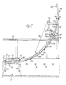
- the numeral 1 indicates the open or bottomless ingot mold of a machine for the continuous casting of metals, including steel, particularly in the form of square section strands up to 150 mm square.
- the ingot mold 1 is of arcuate shape and is solidary with rollers 2 located at its bottom outlet, and is followed, if desired, by a short arcuate cage of guide rolls (not shown), either solidary with or separate and independent from said mold.
- the mold 1 is of the swingable type and is controlled by an oscillator unit 3.
- the ladle 4 pours the molten metal into the tundish 5 therebelow, and the latter, generally, dispenses the molten metal to two or more underlying ingot molds 1, each associated with a casting line.
- the numeral 6 indicates a pail whereinto the molten metal from the intermediate tundish 5 may be poured in an emergency case.
- the cast strand 7 outflowing in a substantially vertical or nearly vertical direction from the bottom opening of the ingot mold follows a curved path of travel along an arc of a circle wherefrom it emerges into a substantially horizontal direction, for example, on a roller runway 8.
- a reversible extractor-straightener device 9 comprising a pair of powered pinch rollers 10, 11.
- the upper pinch roller 11 is carried by a lever 12 pivotable about its fulcrum 13 and may be moved toward and away from the lower roller 10 by means of a hydraulic or pneumatic actuating cylinder 14.
- an upper straightener roller 15 which is arranged on a lever 16 pivoted about the fulcrum 13 and may be raised and lowered by means of a hydraulic or pneumatic actuating cylinder 17.
- the initial portion of the arcuate path of travel of the cast strand 7 is, preferably, devoid of guide means for the strand.
- a strand guide means which may be of any construction and may comprise, for example, idle rollers arranged at least on the extrados side, or a strand guide chute 19 made of plate and arranged on the extrados side.
- said strand guide means are sufficiently offset forwards of the vertical axis at the mold 1, so as to avoid being hit by metal drippings if the solidified skin of the cast strand should break in the spray cooling chamber or thereabove.
- the continuous casting machine has associated therewith a curved starting bar 20, comprised of two successive rigid segments, namely a leading segment 120 and a trailing segment 220, having the same curvature and being pivoted to each other at 21.
- the curvature of the starting bar 20 conforms to the arcuate path of travel of the cast bar 7 between the mold 1 and the extractor-straightener device, and the total length of said starting bar 20 is at least slightly larger than the length of said path of travel between the mold 1 and the pair of pinch rollers 10, 11 of the extractor-straightener device 9.
- the trailing segment 220 of the starting bar 20 preferably, has a cross section corresponding to that of the strand 7 having the smallest section that may be cast with the continuous casting machine, whereas the leading segment 120 of the starting bar 20 has a cross section corresponding to that of the strand 7 to be cast each time. Therefore, when the cross section of the cast strand 7 is changed, only the leading segment 120 of the starting bar 20 needs to be changed. For this purpose, the leading segment 120 of the starting bar 20 is pivoted to the trailing segment 220 in an easily disconnectible and re-connectible manner, by means readily conceivable by those skilled in the art.
- the starting bar 20 has a stowed position downstream of the extractor-straightener device 9 above the roller runway 8 for the cast strand 7.
- a supporting and guiding means for the starting bar along a curved path in the form of an arc of a circle, constituting the extension of the arcuate path of travel of the cast strand 7 between the mold 1 and the extractor-straightener device 9 and having the same curvature thereof.
- the supporting means for the starting bar 20 in the stowage area comprises a structure 22 conforming, with a curved or broken line configuration, to the curved path of travel of the starting bar in the stowage area and comprising a stationary upper portion 222 and a swingable lower arm-like portion 122 pivotable about a fulcrum 23 with respect to the stationary upper portion 222.
- the means for guiding the starting bar 20 on its arcuate path of travel in the stowage area comprises guide rollers 24 carried by the swingable lower arm 122 and by the stationary upper portion 222 of the starting bar supporting structure 22.
- said guide rollers 24 are arranged only on the extrados side of the starting bar 20.
- a pair of powered rollers 25 for displacing the starting bar 20 in the stowage area.
- Said powered rollers 25 may be of the reversible type and are mounted on swingable levers 26 which may be actuated by a hydraulic or pneumatic cylinder 27 so as to move said rollers 25 toward and away from said starting bar 20.
- any suitable locking mechanism (not shown) for holding the starting bar 20 in the stowed position thereof, thus preventing it from sliding down.
- the length of the swingable lower arm 122 of the starting bar supporting structure 22 is substantially the same as the length of the leading segment 120 of said starting bar 20.
- Said swingable lower arm 122 of the supporting structure 22 may be moved angularly about its fulcrum 23 by means of a winch 28 which is mounted on the frame 29 of the continuous casting machine and is connected through the rope 30 to said swingable lower arm 122.
- the starting bar 20 is on the arcuate path of travel of the cast strand between the ingot mold 1 and the extractor-straightener device 9 and is engaged with its connecting head (free end portion of the leading segment 120) in the bottom opening of the mold 1, whereas its trailing end (free end portion of the trailing segment 220) is engaged between said powered rollers 10, 11 of said extractor-straightener device 9.
- the starting bar 20 is then pulled out of the mold 1 and is moved past the extractor-straightener device 9 toward its stowed position by the pair of powered rollers 10, 11 of said extractor-straightener device 9, while the straightener roller 15 is in a raised position.
- the starting bar 20 is thus introduced into the supporting structure 22 in the stowage area, and its trailing segment 220 is engaged between the powered rollers 25 before its leading segment 120 is disengaged from the powered pinch rollers 10, 11 of the extractor-straightener device 9.
- the leading segment 120 of the starting bar 20 disengages from the pair of powered pinch rollers 10, 11 of the extractor-straightener device 9
- the lifting movement of the starting bar 20 in the supporting structure 22 is continued by the action of the pair of powered rollers 25.
- the starting bar 20 is locked against any sliding displacement in the supporting structure 22, for example, only in the stationary upper portion 222 thereof, and the swingable lower arm 122 of the supporting structure 22 is lifted angularly about its pivot 23 by means of the winch 28 and together with the leading segment 120 of the starting bar 20, as shown in figure 3.
- any inspection and maintenance of the connecting head of the starting bar leading segment 120 in view of the next casting step may be effected easily and readily, even during a casting operation, from a working platform or gangway 31.
- an operator on the same working platform can effect the replacement of the leading segment 120 of the starting bar 20 with another leading segment 120 corresponding to the cross section to be cast.
- the working platform or gangway 31 is arranged at such a level to permit to reach easily the pivot 23 of the swingable arm 122 and then the pivot 21 between the two segments 120 and 220 of the starting bar 20.
- the swingable lower arm 122 of the starting bar supporting structure 22 in the stowed position is angularly lowered down about its pivot 23 together with the leading segment 120 of said starting bar 20 into a position in line with the stationary upper portion 222 of said supporting structure 22, thus aligning the leading segment 120 with the trailing segment 220 of the starting bar.
- the starting bar 20 is then unlocked and lowered onto the guides 24 of the supporting structure 22, until the free end of its leading segment 120 is re-engaged between the powered pinch rolls 10, 11 of the extractor-straightener device 9.
- Such a lowering movement of the starting bar 20 may be effected by gravity and may be controlled by a suitable braking action by the rollers 25 and/or may be caused by said powered rollers 25.
- the starting bar 20 is then moved toward the mold 1 along the curved path of travel of the cast strand 7 upstream of the extractor-straightener device 9 by the action of the powered rollers 10, 11 of said machine, which are rotated reversely from the rotation occurred during the casting step.
Landscapes
- Engineering & Computer Science (AREA)
- Mechanical Engineering (AREA)
- Continuous Casting (AREA)
Applications Claiming Priority (2)
| Application Number | Priority Date | Filing Date | Title |
|---|---|---|---|
| IT12611/85A IT1188068B (it) | 1985-11-27 | 1985-11-27 | Macchina per la colata continua in curva con falsa barra rigida |
| IT1261185 | 1985-11-27 |
Publications (1)
| Publication Number | Publication Date |
|---|---|
| EP0224716A1 true EP0224716A1 (fr) | 1987-06-10 |
Family
ID=11142179
Family Applications (1)
| Application Number | Title | Priority Date | Filing Date |
|---|---|---|---|
| EP86114941A Withdrawn EP0224716A1 (fr) | 1985-11-27 | 1986-10-28 | Installation de coulée continu courbe avec mannequin rigide |
Country Status (3)
| Country | Link |
|---|---|
| US (1) | US4715426A (fr) |
| EP (1) | EP0224716A1 (fr) |
| IT (1) | IT1188068B (fr) |
Cited By (1)
| Publication number | Priority date | Publication date | Assignee | Title |
|---|---|---|---|---|
| CN110039018A (zh) * | 2019-04-28 | 2019-07-23 | 中冶南方连铸技术工程有限责任公司 | 柔性引锭杆在线存放装置 |
Families Citing this family (2)
| Publication number | Priority date | Publication date | Assignee | Title |
|---|---|---|---|---|
| US5197533A (en) * | 1990-11-23 | 1993-03-30 | Gunther Behrends | Self-supporting, flexible continuous casting starter bar |
| US5193606A (en) * | 1992-02-10 | 1993-03-16 | Gunther Behrends | Rigid continuous casting starter bar with flexible end for storage |
Citations (5)
| Publication number | Priority date | Publication date | Assignee | Title |
|---|---|---|---|---|
| US3351124A (en) * | 1964-01-28 | 1967-11-07 | Schloemann Ag | Continuous casting plant |
| CH504256A (de) * | 1970-01-27 | 1971-03-15 | Concast Ag | Anfahrkopf zum Giessen von Strangquerschnitten unterschiedlicher Breiten in einer Stranggiessanlage |
| FR2242179A1 (en) * | 1973-08-28 | 1975-03-28 | Uss Eng & Consult | Continuous casting appts mechanism - for handling and downwardly loading starter bars |
| EP0066550A1 (fr) * | 1981-05-20 | 1982-12-08 | DANIELI & C. OFFICINE MECCANICHE S.p.A. | Dispositif pour le stationnement de fausse barre en aval du groupe d'extraction et de dressage |
| EP0066551A1 (fr) * | 1981-05-20 | 1982-12-08 | DANIELI & C. OFFICINE MECCANICHE S.p.A. | Dispositif pour le stationnement de fausse barre en amont d'un groupe d'extraction et de dressage |
Family Cites Families (5)
| Publication number | Priority date | Publication date | Assignee | Title |
|---|---|---|---|---|
| US3344844A (en) * | 1964-08-10 | 1967-10-03 | Koppers Co Inc | Apparatus for handling a curved continuous casting starting bar |
| US3426835A (en) * | 1966-05-11 | 1969-02-11 | Bliss Co | Starting mechanism for continuous casting machine |
| US4043383A (en) * | 1976-09-23 | 1977-08-23 | Koppers Company, Inc. | Continuous casting starting bar and stowage thereof |
| DE3143639A1 (de) * | 1981-11-04 | 1983-05-11 | SMS Schloemann-Siemag AG, 4000 Düsseldorf | Anfahrvorrichtung fuer eine stahlstranggiessanlage |
| US4632175A (en) * | 1985-05-09 | 1986-12-30 | Continuous Casting Systems Inc. | Continuous casting machine |
-
1985
- 1985-11-27 IT IT12611/85A patent/IT1188068B/it active
-
1986
- 1986-10-28 EP EP86114941A patent/EP0224716A1/fr not_active Withdrawn
- 1986-11-07 US US06/928,808 patent/US4715426A/en not_active Expired - Fee Related
Patent Citations (5)
| Publication number | Priority date | Publication date | Assignee | Title |
|---|---|---|---|---|
| US3351124A (en) * | 1964-01-28 | 1967-11-07 | Schloemann Ag | Continuous casting plant |
| CH504256A (de) * | 1970-01-27 | 1971-03-15 | Concast Ag | Anfahrkopf zum Giessen von Strangquerschnitten unterschiedlicher Breiten in einer Stranggiessanlage |
| FR2242179A1 (en) * | 1973-08-28 | 1975-03-28 | Uss Eng & Consult | Continuous casting appts mechanism - for handling and downwardly loading starter bars |
| EP0066550A1 (fr) * | 1981-05-20 | 1982-12-08 | DANIELI & C. OFFICINE MECCANICHE S.p.A. | Dispositif pour le stationnement de fausse barre en aval du groupe d'extraction et de dressage |
| EP0066551A1 (fr) * | 1981-05-20 | 1982-12-08 | DANIELI & C. OFFICINE MECCANICHE S.p.A. | Dispositif pour le stationnement de fausse barre en amont d'un groupe d'extraction et de dressage |
Cited By (1)
| Publication number | Priority date | Publication date | Assignee | Title |
|---|---|---|---|---|
| CN110039018A (zh) * | 2019-04-28 | 2019-07-23 | 中冶南方连铸技术工程有限责任公司 | 柔性引锭杆在线存放装置 |
Also Published As
| Publication number | Publication date |
|---|---|
| US4715426A (en) | 1987-12-29 |
| IT8512611A0 (it) | 1985-11-27 |
| IT1188068B (it) | 1987-12-30 |
Similar Documents
| Publication | Publication Date | Title |
|---|---|---|
| US3344844A (en) | Apparatus for handling a curved continuous casting starting bar | |
| US5277243A (en) | Strip casting | |
| US3495651A (en) | Starting device for continuous castings | |
| US3338297A (en) | Apparatus for bending a casting having a liquid core | |
| CA1036788A (fr) | Appareil de coulee continue a organe d'amorcage souple | |
| US4223715A (en) | Segment exchanger apparatus for a continuous casting installation and method of operating the same | |
| US4715426A (en) | Machine for the curved continuous casting with rigid starting bar | |
| US3814169A (en) | Dummy bar handling system | |
| US3433287A (en) | Dummy bar device for continuous casting machine | |
| US3628595A (en) | Pivotally mounted starter bar in a continuous casting machine | |
| DE3027789C2 (fr) | ||
| US4632175A (en) | Continuous casting machine | |
| US4106550A (en) | Pinch roll stand for use in multi-strand continuous casting machine | |
| EP0066550B1 (fr) | Dispositif pour le stationnement de fausse barre en aval du groupe d'extraction et de dressage | |
| CA1071830A (fr) | Mecanisme d'insertion de la barre de piquage flexible en moulee continue | |
| US4623016A (en) | Device for parking the dummy bar upstream from the extraction and straightening group | |
| US4498520A (en) | Apparatus for the continuous casting of metals | |
| US4703792A (en) | Extractor/straightener device for continuous casting installations | |
| CA1192018A (fr) | Dispositif d'amorcage pour installation de coulee continue, surtout pour l'acier sous forme de pieces longues | |
| CA1097023A (fr) | Traduction non-disponible | |
| CA1064669A (fr) | Machine de coulee continue de l'acier | |
| EP0332939B1 (fr) | Installation de coulée continue arquée pour billettes | |
| US4121652A (en) | Apparatus for separating a starter bar having a starter bar head from a hot strand crop-end in a continuous casting plant | |
| US3823763A (en) | Ramp-type apparatus for disconnecting and storing a flexible starter bar | |
| US3924673A (en) | Apparatus for producing continuous metal castings |
Legal Events
| Date | Code | Title | Description |
|---|---|---|---|
| PUAI | Public reference made under article 153(3) epc to a published international application that has entered the european phase |
Free format text: ORIGINAL CODE: 0009012 |
|
| AK | Designated contracting states |
Kind code of ref document: A1 Designated state(s): AT BE CH DE ES FR GB GR LI LU NL SE |
|
| 17P | Request for examination filed |
Effective date: 19870810 |
|
| 17Q | First examination report despatched |
Effective date: 19880219 |
|
| STAA | Information on the status of an ep patent application or granted ep patent |
Free format text: STATUS: THE APPLICATION IS DEEMED TO BE WITHDRAWN |
|
| 18D | Application deemed to be withdrawn |
Effective date: 19880912 |
|
| RIN1 | Information on inventor provided before grant (corrected) |
Inventor name: KLAUCIC, LUCIANO |