EP0224760A1 - Procédé de fabrication de draps-housses ou enveloppes similaires - Google Patents
Procédé de fabrication de draps-housses ou enveloppes similaires Download PDFInfo
- Publication number
- EP0224760A1 EP0224760A1 EP86115599A EP86115599A EP0224760A1 EP 0224760 A1 EP0224760 A1 EP 0224760A1 EP 86115599 A EP86115599 A EP 86115599A EP 86115599 A EP86115599 A EP 86115599A EP 0224760 A1 EP0224760 A1 EP 0224760A1
- Authority
- EP
- European Patent Office
- Prior art keywords
- cloth
- sewn
- edges
- elastic bands
- web
- Prior art date
- Legal status (The legal status is an assumption and is not a legal conclusion. Google has not performed a legal analysis and makes no representation as to the accuracy of the status listed.)
- Granted
Links
- 238000004519 manufacturing process Methods 0.000 title claims description 8
- 239000004744 fabric Substances 0.000 claims abstract description 70
- 238000000034 method Methods 0.000 claims abstract description 19
- 238000005520 cutting process Methods 0.000 claims abstract description 17
- 239000000463 material Substances 0.000 claims description 36
- 238000009958 sewing Methods 0.000 claims description 28
- 230000001681 protective effect Effects 0.000 claims description 3
- 230000015572 biosynthetic process Effects 0.000 claims description 2
- 238000005259 measurement Methods 0.000 claims description 2
- 239000003086 colorant Substances 0.000 description 3
- 238000012432 intermediate storage Methods 0.000 description 2
- 238000000926 separation method Methods 0.000 description 2
- 206010040954 Skin wrinkling Diseases 0.000 description 1
- 230000001939 inductive effect Effects 0.000 description 1
- 239000002184 metal Substances 0.000 description 1
- 230000003287 optical effect Effects 0.000 description 1
- 239000007858 starting material Substances 0.000 description 1
- 238000003860 storage Methods 0.000 description 1
- 239000004753 textile Substances 0.000 description 1
- 230000035899 viability Effects 0.000 description 1
Images


Classifications
-
- D—TEXTILES; PAPER
- D05—SEWING; EMBROIDERING; TUFTING
- D05B—SEWING
- D05B25/00—Sewing units consisting of combinations of several sewing machines
-
- A—HUMAN NECESSITIES
- A47—FURNITURE; DOMESTIC ARTICLES OR APPLIANCES; COFFEE MILLS; SPICE MILLS; SUCTION CLEANERS IN GENERAL
- A47G—HOUSEHOLD OR TABLE EQUIPMENT
- A47G9/00—Bed-covers; Counterpanes; Travelling rugs; Sleeping rugs; Sleeping bags; Pillows
- A47G9/02—Bed linen; Blankets; Counterpanes
- A47G9/0238—Bed linen
- A47G9/0246—Fitted sheets
-
- B—PERFORMING OPERATIONS; TRANSPORTING
- B65—CONVEYING; PACKING; STORING; HANDLING THIN OR FILAMENTARY MATERIAL
- B65H—HANDLING THIN OR FILAMENTARY MATERIAL, e.g. SHEETS, WEBS, CABLES
- B65H2301/00—Handling processes for sheets or webs
- B65H2301/30—Orientation, displacement, position of the handled material
- B65H2301/34—Modifying, selecting, changing direction of displacement
- B65H2301/341—Modifying, selecting, changing direction of displacement without change of plane of displacement
-
- D—TEXTILES; PAPER
- D05—SEWING; EMBROIDERING; TUFTING
- D05D—INDEXING SCHEME ASSOCIATED WITH SUBCLASSES D05B AND D05C, RELATING TO SEWING, EMBROIDERING AND TUFTING
- D05D2305/00—Operations on the work before or after sewing
- D05D2305/08—Cutting the workpiece
-
- D—TEXTILES; PAPER
- D10—INDEXING SCHEME ASSOCIATED WITH SUBLASSES OF SECTION D, RELATING TO TEXTILES
- D10B—INDEXING SCHEME ASSOCIATED WITH SUBLASSES OF SECTION D, RELATING TO TEXTILES
- D10B2503/00—Domestic or personal
- D10B2503/06—Bed linen
- D10B2503/062—Fitted bedsheets
Definitions
- the invention relates to a method for producing fitted sheets or similar protective covers, in which rectangular pieces of cloth are cut off from a web, the corners of which are separated by approximately rectangular cutouts, two adjacent cut edges then being connected by a seam, and in which Tensioning elastic bands or the like can be sewn on or sewn into the appropriately folded cloth edges in the tensioned state, which in the relaxed state cause the cloth to contract with the formation of folds or curls.
- fitted sheets have been made from textiles or textile-like materials (so-called non-woven materials) in a predominantly manual working process.
- the web material is first laid in a stack with a long-laying machine, and this stack is then cut through in the middle, and the corners at the cut edges are finally separated by rectangular or approximately rectangular cutouts on the resulting two stack halves. All other operations for the production of the fitted sheets must then be carried out manually.
- the blanks are transported to a manual sewing station, where the respective adjacent two cut edges in the area of the cut cloth corner are placed flush on top of each other and sewn together. If in this way the four required connecting seams are attached to each piece of cloth, you will - in spatial terms - already get a box-like cloth structure.
- the elastic bands or similar tensioning elements are then to be attached to these now partially assembled fitted sheets.
- This is done at another manual sewing station, to which the partially assembled fitted sheets have to be transported.
- the elastic bands are usually tightened on the cloth edges along the two narrow sides of the partially assembled fitted sheet. sewn in that they run a bit beyond the respective corner into the long side of the fitted sheet in question and, when relaxed, pull the fabric together or curl in the corner area.
- a disadvantage of this manufacturing method is, above all, the relatively high amount of manual work involved, although it should be noted that the work processes described above rule out automatic, automatic production of the fitted sheets.
- undesired transport paths for the sewing material are required, for which a relatively large amount of space is also required for intermediate storage.
- the invention is based on the object of specifying a more economical and predominantly mechanically executable manufacturing method for fitted sheets or similar protective covers. This process should also save transport routes and storage space for the sewing material.
- the method according to the invention has the advantages that the application of the markings to the web material and the attaching or sewing in of the tensioning elastic bands in the tensioned state to the edges of the web material or to the pieces of cloth separated therefrom can take place completely automatically, ie automatically in a corresponding device .
- This eliminates the time-consuming manual work in connection with the elastic straps, which was made even more difficult by the fact that they are to be sewn or sewn on in the tensioned state.
- Executed manually are according to the inventive method only the diagonal folding at each corner of a piece of cloth, the sewing together of these folded sections of cloth and their separation, which is a problem for a skilled seamstress, since it is relatively short seams and lengths of cut to be placed flat goods.
- the method according to the invention also reduces the transport routes for the sewing material and the space for intermediate storage of the same in comparison to the prior art, since only a manual sewing station is required.
- a saving in the elastic bands and thus a further increase in the economy of the method according to the invention is achieved in that the elastic bands are sewn on or sewn in at a distance from the corners of a piece of cloth. If the folded cloth sections are then cut off with the corners, no or practically no tensioning rubber is lost.
- the tensioning rubber bands for a piece of cloth come to the cloth edges at a mutual distance from one another be sewn in. You can get by without affecting the function of such fitted sheets, namely with relatively short elastic bands on the edges of the sheet opposite both sides of the respective connecting seam.
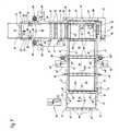
- a web material 10 serves as the starting material for the fitted sheets, one of which is shown almost completed at 9 in FIG. 2, which is drawn off from a supply stack 12 via a deflection roller 11, inter alia by a drive roller 13, which is driven intermittently by an electric motor 14 .
- a deflection roller 11 inter alia by a drive roller 13, which is driven intermittently by an electric motor 14 .
- dancer rolls which stretch the web material 10 in the longitudinal direction before it runs over a further drive roller 16 in the direction of the cutting station 18.
- the drive roller 16 is driven intermittently by an electric motor 17 in synchronism with the drive roller 13.
- the cutting station 18 comprises a separating knife 19 which can be moved up and down by a motor and a stationary counter knife 20.
- the two knives 19, 20 are preceded by a holding bar 21 which can be moved up and down by a drive means (not shown) and which interacts with a support plate located under the web material 10, to clamp the web material 10 before the cutting knife 19 comes into operation. Even after the separating cut has been made, the web material 10 is still clamped briefly, for reasons that will be described later. Between the drive roller 13 and the deflection roller 11 also extends a support plate below the web material 10.
- a measuring wheel 22 which is driven when the web material 10 is pulled off from the supply stack 12, is drive-connected to an encoder 23, which, among other things, controls the electric motors via a control circuit 14, 17 controls that a web length, which corresponds to the cutting length of a fitted sheet, is subtracted from the supply stack 12.
- an encoder 23 which, among other things, controls the electric motors via a control circuit 14, 17 controls that a web length, which corresponds to the cutting length of a fitted sheet, is subtracted from the supply stack 12.
- two marking devices 24 come into operation, which place four marking points 25, 26 next to each longitudinal edge 27 of the web material 10.
- these marking points can consist of contrasting colors, including fluorescent colors for optical scanning, metal-containing colors for inductive or capacitive scanning, etc.
- the marking points 26 are sensed by sensors, not shown, which control a feed device 28 for a tensioning elastic band 31 and the drive motor 29 for a sewing machine 30 with respect to each longitudinal edge 27 of the web material 10 via a control circuit.
- the marking points 26 switch on the feed devices 28 for the elastic band 31, which is indicated by only schematically indicated guiding and tensioning devices 33 is guided parallel to the longitudinal edges 27 against the web material 10 in the tensioned state, so that it is sewn onto the web material 10 parallel to the edges when the sewing machines 30 are reached.
- the marking points 26 also control the drive of the separating knife 19, which can be moved up and down, via sensors (not shown) such that the separating cut runs between two marking points 25, 26 spaced apart in the longitudinal direction of the web material 10.
- the separated piece of cloth 34 can be transported transversely to the longitudinal direction of the web material 10 by lower transport belts 35 and upper transport belts 36 and 37 to the left in the direction of the arrow according to FIG.
- the bracket 32 is driven on a guide, not shown, by an endless drive member 38 to and fro via the electric motor 39.
- a lifting device 40 lifts the upper transport belts 36 to such an extent that the clamp 32 can be moved under the transport belts 36 against the cutting station 18 and back.
- the control of the electric motor 39 for driving the clamp 32 and its gripping movement is carried out by the transmitter 23 via the control circuit already mentioned, in synchronism with the electric motors 14, 17 of the drive rollers 13, 16.
- the clamp 32 After the web material 10 has been released by the holding strip 21, the clamp 32 is moved back into its starting position shown in FIG. 7, while at the same time the drive rollers 13, 16 are activated in order to pull off a further cutting length of the web product 10 from the supply stack 12. When this cutting length is reached, the motors 14, 17 and 39 are switched off again. After a further piece of cloth 34 has been cut off by the separating knife 19 and this piece of cloth 34 has been removed to the left in the direction of the arrow according to FIG. 7, the clamp 32 is moved again against the cutting station 18 and the process described is repeated. The actuation of the holding bar 21 and the separating knife 19 and the lifting device 40 controls the electrical control circuit already mentioned, which is electrically connected to the transmitter 23.
- the upper transport belts 37 are driven by an electric motor 43, in synchronism with the lower transport belts 35 driven by an electric motor, not shown, and the upper transport belts 36 are driven by an electric motor 44 which is supported by a frame 45 which is carried by the lifting device 40 can be raised and lowered.
- the motors 43, 44 for the transport belts 37, 36 and the motor (not shown) for the lower transport belts 35 can also be controlled by the transmitter 23 via the electrical control circuit with a corresponding time delay, or by sensors which control the longitudinal edges 27a of the cloth pieces 34 scan in the range of movement of the clamp 32.
- the elastic bands 31 'and 31' along the longitudinal edges 27a and transverse edges 41 of a piece of cloth 34 are arranged at a mutual distance from one another and also at equal distances from each corner 47 of a piece of cloth 34.
- the sewn on in the above manner in the tensioned state Tensioning elastic bands 31 'and 31 ⁇ produce in the relaxed state the ripples or folds indicated in Fig. 1 on the piece of cloth 34.
- the sewing of the elastic bands described above on the longitudinal edges 27 of the web material 10 and on the transverse edges 41 of the cloth pieces 34 takes place in a state in which the web material 10 or cloth pieces 34 are held in a flat state and are moved in the directions indicated by arrows in FIG. 7.
- so-called hem bags can be provided in the area of the feed devices 28, 28 'for the elastic bands 31, which fold over the longitudinal edges 27 of the web material 10 or the transverse edges 41 of the cloth pieces 34, so that the elastic bands can be sewn into these folded cloth edges .
- the control of the feed devices 28, 28 'for the rubber bands 31 can also be carried out in a departure from the embodiment in such a way that e.g. A continuous elastic band is arranged on the longitudinal edges 27a and / or transverse edges 41 of the cloth pieces 34, but is preferably at the distance described in connection with the exemplary embodiment with respect to the adjacent corners 47.
Landscapes
- Engineering & Computer Science (AREA)
- Textile Engineering (AREA)
- Sewing Machines And Sewing (AREA)
- Treatment Of Fiber Materials (AREA)
Applications Claiming Priority (3)
| Application Number | Priority Date | Filing Date | Title |
|---|---|---|---|
| DE3542394A DE3542394C1 (de) | 1985-11-30 | 1985-11-30 | Vorrichtung zur Herstellung von teilweise konfektionierten Spannbettuechern oder dergleichen Schonbezuegen |
| DE3542445 | 1985-11-30 | ||
| DE3542445A DE3542445C1 (de) | 1985-11-30 | 1985-11-30 | Verfahren zur Herstellung von Spannbettuechern oder dergleichen Schonbezuegen |
Publications (2)
| Publication Number | Publication Date |
|---|---|
| EP0224760A1 true EP0224760A1 (fr) | 1987-06-10 |
| EP0224760B1 EP0224760B1 (fr) | 1989-05-24 |
Family
ID=25838357
Family Applications (1)
| Application Number | Title | Priority Date | Filing Date |
|---|---|---|---|
| EP86115599A Expired EP0224760B1 (fr) | 1985-11-30 | 1986-11-11 | Procédé de fabrication de draps-housses ou enveloppes similaires |
Country Status (2)
| Country | Link |
|---|---|
| EP (1) | EP0224760B1 (fr) |
| DE (1) | DE3542394C1 (fr) |
Cited By (2)
| Publication number | Priority date | Publication date | Assignee | Title |
|---|---|---|---|---|
| EP0319683A3 (en) * | 1987-11-04 | 1989-08-09 | Texpa Arbter Maschinenbau Gmbh | Automatic sewing station |
| EP0558716A4 (en) * | 1991-09-19 | 1994-12-07 | Sew Simple Systems Inc | Fitted sheet hemmer |
Families Citing this family (2)
| Publication number | Priority date | Publication date | Assignee | Title |
|---|---|---|---|---|
| DE3638989C1 (en) * | 1986-11-14 | 1988-02-11 | Texpa Arbter Maschb Gmbh | Apparatus for making at least one hem on a cloth material having a sewn-in tape, especially rubber tape |
| US4773341A (en) * | 1987-10-21 | 1988-09-27 | Sew Simple Systems, Inc. | Fitted sheet hemmer |
Citations (6)
| Publication number | Priority date | Publication date | Assignee | Title |
|---|---|---|---|---|
| CH411255A (de) * | 1962-04-03 | 1966-04-15 | Springs Cotton Mills | Gewobener Matratzenüberzug und Verfahren zu dessen Herstellung |
| DE1760888A1 (de) * | 1968-07-15 | 1971-12-30 | Feldmuehle Ag | Verfahren zum kontinuierlichen Fertigen von Decken |
| FR2284249A7 (fr) * | 1974-09-09 | 1976-04-02 | Chapellerie Ste Ind | Procede de fabrication d'une enveloppe souple, notamment d'une housse pour matelas et enveloppe obtenue suivant ce procede |
| US3955515A (en) * | 1974-10-07 | 1976-05-11 | Nemo Industries, Inc. | Folding and hemming method and apparatus |
| FR2506590A1 (fr) * | 1981-05-27 | 1982-12-03 | Duhamel Sarl Maurice | Drap housse |
| DE3347143A1 (de) * | 1983-01-06 | 1984-07-12 | Bassetti S.p.A., Milano | Verfahren zur fertigung von abstreifbaren huellen zum straffen ueberziehen von dreidimensionalen gegenstaenden |
-
1985
- 1985-11-30 DE DE3542394A patent/DE3542394C1/de not_active Expired
-
1986
- 1986-11-11 EP EP86115599A patent/EP0224760B1/fr not_active Expired
Patent Citations (6)
| Publication number | Priority date | Publication date | Assignee | Title |
|---|---|---|---|---|
| CH411255A (de) * | 1962-04-03 | 1966-04-15 | Springs Cotton Mills | Gewobener Matratzenüberzug und Verfahren zu dessen Herstellung |
| DE1760888A1 (de) * | 1968-07-15 | 1971-12-30 | Feldmuehle Ag | Verfahren zum kontinuierlichen Fertigen von Decken |
| FR2284249A7 (fr) * | 1974-09-09 | 1976-04-02 | Chapellerie Ste Ind | Procede de fabrication d'une enveloppe souple, notamment d'une housse pour matelas et enveloppe obtenue suivant ce procede |
| US3955515A (en) * | 1974-10-07 | 1976-05-11 | Nemo Industries, Inc. | Folding and hemming method and apparatus |
| FR2506590A1 (fr) * | 1981-05-27 | 1982-12-03 | Duhamel Sarl Maurice | Drap housse |
| DE3347143A1 (de) * | 1983-01-06 | 1984-07-12 | Bassetti S.p.A., Milano | Verfahren zur fertigung von abstreifbaren huellen zum straffen ueberziehen von dreidimensionalen gegenstaenden |
Cited By (2)
| Publication number | Priority date | Publication date | Assignee | Title |
|---|---|---|---|---|
| EP0319683A3 (en) * | 1987-11-04 | 1989-08-09 | Texpa Arbter Maschinenbau Gmbh | Automatic sewing station |
| EP0558716A4 (en) * | 1991-09-19 | 1994-12-07 | Sew Simple Systems Inc | Fitted sheet hemmer |
Also Published As
| Publication number | Publication date |
|---|---|
| DE3542394C1 (de) | 1987-02-26 |
| EP0224760B1 (fr) | 1989-05-24 |
Similar Documents
| Publication | Publication Date | Title |
|---|---|---|
| DE3542445C1 (de) | Verfahren zur Herstellung von Spannbettuechern oder dergleichen Schonbezuegen | |
| DE69717894T2 (de) | Verfahren und Vorrichtung zum Trennen einer Materialbahn an einer Schwächungslinie | |
| DE69407743T2 (de) | Vorrichtung zum Festnähen von Stoffstücken an einen Reissverschluss | |
| EP0120251A1 (fr) | Procédé et dispositif d'enveloppement d'objets de préférence quadrangulaires avec un matériau d'emballage sous forme de bande | |
| DE3811138A1 (de) | Verfahren und vorrichtung zum behandeln des endabschnitts von aufgerolltem papier | |
| DE69213622T2 (de) | Automatische Nähvorrichtung zur Bildung eines rohrförmigen Ärmels durch Säumen und Schliessen eines Ärmelrohlings | |
| DE3886521T2 (de) | Vorrichtung zum säumen von angepassten textil-flächengebilden. | |
| EP0387371B1 (fr) | Procédé et dispositif de coupe d'éléments pour vêtements | |
| DE2624055C3 (de) | Verfahren und Vorrichtung zum Herstellen von Textiletiketten in RoUenform | |
| EP0043044A1 (fr) | Etiquette et machine pour confectionner des étiquettes | |
| EP0224760B1 (fr) | Procédé de fabrication de draps-housses ou enveloppes similaires | |
| DE69014689T2 (de) | Verfahren und Vorrichtung zum Auslegen von mit Schablonen versehenen Materialbahnen zum automatischen Anpassen. | |
| DE10204313A1 (de) | Verfahren und Vorrichtung zum Abschneiden von Etikettenhülsen von einem flachliegenden Etikettenschlauchband | |
| DE69205213T2 (de) | Vorrichtung zur Zuführen einer endlosen Kunststoff-Folie. | |
| DE3818796C1 (fr) | ||
| EP2253753B1 (fr) | Procédé pour coudre un produit de couture | |
| CH661281A5 (de) | Rolle eines klebebandes mit beidseitig klebenden klebematerialstuecken und vorrichtungen zur herstellung derselben. | |
| DE69217293T2 (de) | Automatischer Nähapparat zum Säumen und Ärmelschliessen | |
| DE1806238C3 (de) | Vorrichtung zum Einnähen eines fortlaufenden Reißverschlußbandes in einen durch einen Schlitz zweigeteilten Träger | |
| DE1479312A1 (de) | Maschine zur Ausfuehrung von Applikationen und Arbeiten im Innern eines schlauchfoermigen,durchgehenden Werkstueckes aus thermoplastischem od.dgl. Material | |
| DE3521951C2 (fr) | ||
| EP0401234B1 (fr) | Dispositif de plissage et de couture de plis | |
| DE69206502T2 (de) | Vorrichtung und Verfahren zum Verschliessen und seitlichen Versiegeln von Bogen oder dergleichen enthaltenden, in Kunststoffolie eingewickelten Paketen. | |
| DE4233878A1 (de) | Vorrichtung zum Schweißen und Trennen thermisch verschweißbarer Einfaßbänder aus Kunststoff mit textilem Charakter | |
| DE2648235C2 (de) | Vorrichtung zum automatischen Herstellen mehrmals gefalteter, vernähter Sackböden |
Legal Events
| Date | Code | Title | Description |
|---|---|---|---|
| PUAI | Public reference made under article 153(3) epc to a published international application that has entered the european phase |
Free format text: ORIGINAL CODE: 0009012 |
|
| 17P | Request for examination filed |
Effective date: 19861204 |
|
| AK | Designated contracting states |
Kind code of ref document: A1 Designated state(s): FR GB IT SE |
|
| 17Q | First examination report despatched |
Effective date: 19880513 |
|
| GRAA | (expected) grant |
Free format text: ORIGINAL CODE: 0009210 |
|
| AK | Designated contracting states |
Kind code of ref document: B1 Designated state(s): FR GB IT SE |
|
| GBT | Gb: translation of ep patent filed (gb section 77(6)(a)/1977) | ||
| ET | Fr: translation filed | ||
| ITF | It: translation for a ep patent filed | ||
| PLBE | No opposition filed within time limit |
Free format text: ORIGINAL CODE: 0009261 |
|
| STAA | Information on the status of an ep patent application or granted ep patent |
Free format text: STATUS: NO OPPOSITION FILED WITHIN TIME LIMIT |
|
| 26N | No opposition filed | ||
| ITTA | It: last paid annual fee | ||
| EAL | Se: european patent in force in sweden |
Ref document number: 86115599.2 |
|
| PGFP | Annual fee paid to national office [announced via postgrant information from national office to epo] |
Ref country code: FR Payment date: 19970917 Year of fee payment: 12 |
|
| PGFP | Annual fee paid to national office [announced via postgrant information from national office to epo] |
Ref country code: GB Payment date: 19971020 Year of fee payment: 12 |
|
| PG25 | Lapsed in a contracting state [announced via postgrant information from national office to epo] |
Ref country code: GB Free format text: LAPSE BECAUSE OF NON-PAYMENT OF DUE FEES Effective date: 19981111 |
|
| PGFP | Annual fee paid to national office [announced via postgrant information from national office to epo] |
Ref country code: SE Payment date: 19981119 Year of fee payment: 13 |
|
| GBPC | Gb: european patent ceased through non-payment of renewal fee |
Effective date: 19981111 |
|
| PG25 | Lapsed in a contracting state [announced via postgrant information from national office to epo] |
Ref country code: FR Free format text: LAPSE BECAUSE OF NON-PAYMENT OF DUE FEES Effective date: 19990730 |
|
| REG | Reference to a national code |
Ref country code: FR Ref legal event code: ST |
|
| PG25 | Lapsed in a contracting state [announced via postgrant information from national office to epo] |
Ref country code: SE Free format text: LAPSE BECAUSE OF NON-PAYMENT OF DUE FEES Effective date: 19991112 |
|
| EUG | Se: european patent has lapsed |
Ref document number: 86115599.2 |
|
| PG25 | Lapsed in a contracting state [announced via postgrant information from national office to epo] |
Ref country code: IT Free format text: LAPSE BECAUSE OF NON-PAYMENT OF DUE FEES;WARNING: LAPSES OF ITALIAN PATENTS WITH EFFECTIVE DATE BEFORE 2007 MAY HAVE OCCURRED AT ANY TIME BEFORE 2007. THE CORRECT EFFECTIVE DATE MAY BE DIFFERENT FROM THE ONE RECORDED. Effective date: 20051111 |