EP0224808A1 - Vorrichtung zum kontinuierlichen Schweissen bzw. Siegeln von Nähten von Kunststoff-Folien - Google Patents
Vorrichtung zum kontinuierlichen Schweissen bzw. Siegeln von Nähten von Kunststoff-Folien Download PDFInfo
- Publication number
- EP0224808A1 EP0224808A1 EP86116118A EP86116118A EP0224808A1 EP 0224808 A1 EP0224808 A1 EP 0224808A1 EP 86116118 A EP86116118 A EP 86116118A EP 86116118 A EP86116118 A EP 86116118A EP 0224808 A1 EP0224808 A1 EP 0224808A1
- Authority
- EP
- European Patent Office
- Prior art keywords
- sealing
- sealing drum
- roller
- heating tape
- tape
- Prior art date
- Legal status (The legal status is an assumption and is not a legal conclusion. Google has not performed a legal analysis and makes no representation as to the accuracy of the status listed.)
- Granted
Links
- 238000007789 sealing Methods 0.000 title claims abstract description 111
- 238000003466 welding Methods 0.000 title claims description 12
- 239000002985 plastic film Substances 0.000 title claims description 6
- 229920006255 plastic film Polymers 0.000 title claims description 6
- 238000010438 heat treatment Methods 0.000 claims abstract description 55
- 238000001816 cooling Methods 0.000 claims abstract description 29
- 229910000831 Steel Inorganic materials 0.000 claims abstract description 22
- 239000010959 steel Substances 0.000 claims abstract description 22
- 230000000181 anti-adherent effect Effects 0.000 claims description 8
- 238000000576 coating method Methods 0.000 claims description 6
- 238000013021 overheating Methods 0.000 claims description 5
- 229910000851 Alloy steel Inorganic materials 0.000 claims description 4
- 239000011248 coating agent Substances 0.000 claims description 4
- OKTJSMMVPCPJKN-UHFFFAOYSA-N Carbon Chemical compound [C] OKTJSMMVPCPJKN-UHFFFAOYSA-N 0.000 claims description 2
- 229910000990 Ni alloy Inorganic materials 0.000 claims description 2
- 229910052799 carbon Inorganic materials 0.000 claims description 2
- 230000002093 peripheral effect Effects 0.000 claims 1
- 238000004804 winding Methods 0.000 abstract description 3
- 239000011888 foil Substances 0.000 description 5
- 238000004519 manufacturing process Methods 0.000 description 4
- 239000000463 material Substances 0.000 description 3
- 239000004033 plastic Substances 0.000 description 3
- 229920003023 plastic Polymers 0.000 description 3
- 238000010924 continuous production Methods 0.000 description 2
- 238000009826 distribution Methods 0.000 description 2
- 238000005299 abrasion Methods 0.000 description 1
- 239000000853 adhesive Substances 0.000 description 1
- 230000001070 adhesive effect Effects 0.000 description 1
- 230000015572 biosynthetic process Effects 0.000 description 1
- 239000000110 cooling liquid Substances 0.000 description 1
- 230000017525 heat dissipation Effects 0.000 description 1
- 239000004922 lacquer Substances 0.000 description 1
- 238000000465 moulding Methods 0.000 description 1
- 238000012536 packaging technology Methods 0.000 description 1
- 239000006223 plastic coating Substances 0.000 description 1
- 229920001296 polysiloxane Polymers 0.000 description 1
- 238000007639 printing Methods 0.000 description 1
- 230000005855 radiation Effects 0.000 description 1
- 230000001105 regulatory effect Effects 0.000 description 1
- 230000000284 resting effect Effects 0.000 description 1
- 238000007493 shaping process Methods 0.000 description 1
- 239000007858 starting material Substances 0.000 description 1
- XLYOFNOQVPJJNP-UHFFFAOYSA-N water Substances O XLYOFNOQVPJJNP-UHFFFAOYSA-N 0.000 description 1
Images

Classifications
-
- B—PERFORMING OPERATIONS; TRANSPORTING
- B29—WORKING OF PLASTICS; WORKING OF SUBSTANCES IN A PLASTIC STATE IN GENERAL
- B29C—SHAPING OR JOINING OF PLASTICS; SHAPING OF MATERIAL IN A PLASTIC STATE, NOT OTHERWISE PROVIDED FOR; AFTER-TREATMENT OF THE SHAPED PRODUCTS, e.g. REPAIRING
- B29C66/00—General aspects of processes or apparatus for joining preformed parts
- B29C66/01—General aspects dealing with the joint area or with the area to be joined
- B29C66/05—Particular design of joint configurations
- B29C66/10—Particular design of joint configurations particular design of the joint cross-sections
- B29C66/11—Joint cross-sections comprising a single joint-segment, i.e. one of the parts to be joined comprising a single joint-segment in the joint cross-section
- B29C66/112—Single lapped joints
- B29C66/1122—Single lap to lap joints, i.e. overlap joints
-
- B—PERFORMING OPERATIONS; TRANSPORTING
- B29—WORKING OF PLASTICS; WORKING OF SUBSTANCES IN A PLASTIC STATE IN GENERAL
- B29C—SHAPING OR JOINING OF PLASTICS; SHAPING OF MATERIAL IN A PLASTIC STATE, NOT OTHERWISE PROVIDED FOR; AFTER-TREATMENT OF THE SHAPED PRODUCTS, e.g. REPAIRING
- B29C53/00—Shaping by bending, folding, twisting, straightening or flattening; Apparatus therefor
- B29C53/36—Bending and joining, e.g. for making hollow articles
- B29C53/38—Bending and joining, e.g. for making hollow articles by bending sheets or strips at right angles to the longitudinal axis of the article being formed and joining the edges
- B29C53/387—Bending and joining, e.g. for making hollow articles by bending sheets or strips at right angles to the longitudinal axis of the article being formed and joining the edges the joining being done from the inside
-
- B—PERFORMING OPERATIONS; TRANSPORTING
- B29—WORKING OF PLASTICS; WORKING OF SUBSTANCES IN A PLASTIC STATE IN GENERAL
- B29C—SHAPING OR JOINING OF PLASTICS; SHAPING OF MATERIAL IN A PLASTIC STATE, NOT OTHERWISE PROVIDED FOR; AFTER-TREATMENT OF THE SHAPED PRODUCTS, e.g. REPAIRING
- B29C53/00—Shaping by bending, folding, twisting, straightening or flattening; Apparatus therefor
- B29C53/36—Bending and joining, e.g. for making hollow articles
- B29C53/38—Bending and joining, e.g. for making hollow articles by bending sheets or strips at right angles to the longitudinal axis of the article being formed and joining the edges
- B29C53/48—Bending and joining, e.g. for making hollow articles by bending sheets or strips at right angles to the longitudinal axis of the article being formed and joining the edges for articles of indefinite length, i.e. bending a strip progressively
-
- B—PERFORMING OPERATIONS; TRANSPORTING
- B29—WORKING OF PLASTICS; WORKING OF SUBSTANCES IN A PLASTIC STATE IN GENERAL
- B29C—SHAPING OR JOINING OF PLASTICS; SHAPING OF MATERIAL IN A PLASTIC STATE, NOT OTHERWISE PROVIDED FOR; AFTER-TREATMENT OF THE SHAPED PRODUCTS, e.g. REPAIRING
- B29C65/00—Joining or sealing of preformed parts, e.g. welding of plastics materials; Apparatus therefor
- B29C65/02—Joining or sealing of preformed parts, e.g. welding of plastics materials; Apparatus therefor by heating, with or without pressure
- B29C65/18—Joining or sealing of preformed parts, e.g. welding of plastics materials; Apparatus therefor by heating, with or without pressure using heated tools
-
- B—PERFORMING OPERATIONS; TRANSPORTING
- B29—WORKING OF PLASTICS; WORKING OF SUBSTANCES IN A PLASTIC STATE IN GENERAL
- B29C—SHAPING OR JOINING OF PLASTICS; SHAPING OF MATERIAL IN A PLASTIC STATE, NOT OTHERWISE PROVIDED FOR; AFTER-TREATMENT OF THE SHAPED PRODUCTS, e.g. REPAIRING
- B29C65/00—Joining or sealing of preformed parts, e.g. welding of plastics materials; Apparatus therefor
- B29C65/02—Joining or sealing of preformed parts, e.g. welding of plastics materials; Apparatus therefor by heating, with or without pressure
- B29C65/18—Joining or sealing of preformed parts, e.g. welding of plastics materials; Apparatus therefor by heating, with or without pressure using heated tools
- B29C65/22—Heated wire resistive ribbon, resistive band or resistive strip
- B29C65/221—Heated wire resistive ribbon, resistive band or resistive strip characterised by the type of heated wire, resistive ribbon, band or strip
- B29C65/224—Heated wire resistive ribbon, resistive band or resistive strip characterised by the type of heated wire, resistive ribbon, band or strip being a resistive ribbon, a resistive band or a resistive strip
-
- B—PERFORMING OPERATIONS; TRANSPORTING
- B29—WORKING OF PLASTICS; WORKING OF SUBSTANCES IN A PLASTIC STATE IN GENERAL
- B29C—SHAPING OR JOINING OF PLASTICS; SHAPING OF MATERIAL IN A PLASTIC STATE, NOT OTHERWISE PROVIDED FOR; AFTER-TREATMENT OF THE SHAPED PRODUCTS, e.g. REPAIRING
- B29C65/00—Joining or sealing of preformed parts, e.g. welding of plastics materials; Apparatus therefor
- B29C65/02—Joining or sealing of preformed parts, e.g. welding of plastics materials; Apparatus therefor by heating, with or without pressure
- B29C65/18—Joining or sealing of preformed parts, e.g. welding of plastics materials; Apparatus therefor by heating, with or without pressure using heated tools
- B29C65/22—Heated wire resistive ribbon, resistive band or resistive strip
- B29C65/228—Heated wire resistive ribbon, resistive band or resistive strip characterised by the means for electrically connecting the ends of said heated wire, resistive ribbon, resistive band or resistive strip
-
- B—PERFORMING OPERATIONS; TRANSPORTING
- B29—WORKING OF PLASTICS; WORKING OF SUBSTANCES IN A PLASTIC STATE IN GENERAL
- B29C—SHAPING OR JOINING OF PLASTICS; SHAPING OF MATERIAL IN A PLASTIC STATE, NOT OTHERWISE PROVIDED FOR; AFTER-TREATMENT OF THE SHAPED PRODUCTS, e.g. REPAIRING
- B29C65/00—Joining or sealing of preformed parts, e.g. welding of plastics materials; Apparatus therefor
- B29C65/48—Joining or sealing of preformed parts, e.g. welding of plastics materials; Apparatus therefor using adhesives, i.e. using supplementary joining material; solvent bonding
- B29C65/4805—Joining or sealing of preformed parts, e.g. welding of plastics materials; Apparatus therefor using adhesives, i.e. using supplementary joining material; solvent bonding characterised by the type of adhesives
- B29C65/481—Non-reactive adhesives, e.g. physically hardening adhesives
- B29C65/4815—Hot melt adhesives, e.g. thermoplastic adhesives
-
- B—PERFORMING OPERATIONS; TRANSPORTING
- B29—WORKING OF PLASTICS; WORKING OF SUBSTANCES IN A PLASTIC STATE IN GENERAL
- B29C—SHAPING OR JOINING OF PLASTICS; SHAPING OF MATERIAL IN A PLASTIC STATE, NOT OTHERWISE PROVIDED FOR; AFTER-TREATMENT OF THE SHAPED PRODUCTS, e.g. REPAIRING
- B29C65/00—Joining or sealing of preformed parts, e.g. welding of plastics materials; Apparatus therefor
- B29C65/48—Joining or sealing of preformed parts, e.g. welding of plastics materials; Apparatus therefor using adhesives, i.e. using supplementary joining material; solvent bonding
- B29C65/50—Joining or sealing of preformed parts, e.g. welding of plastics materials; Apparatus therefor using adhesives, i.e. using supplementary joining material; solvent bonding using adhesive tape, e.g. thermoplastic tape; using threads or the like
- B29C65/5042—Joining or sealing of preformed parts, e.g. welding of plastics materials; Apparatus therefor using adhesives, i.e. using supplementary joining material; solvent bonding using adhesive tape, e.g. thermoplastic tape; using threads or the like covering both elements to be joined
-
- B—PERFORMING OPERATIONS; TRANSPORTING
- B29—WORKING OF PLASTICS; WORKING OF SUBSTANCES IN A PLASTIC STATE IN GENERAL
- B29C—SHAPING OR JOINING OF PLASTICS; SHAPING OF MATERIAL IN A PLASTIC STATE, NOT OTHERWISE PROVIDED FOR; AFTER-TREATMENT OF THE SHAPED PRODUCTS, e.g. REPAIRING
- B29C65/00—Joining or sealing of preformed parts, e.g. welding of plastics materials; Apparatus therefor
- B29C65/48—Joining or sealing of preformed parts, e.g. welding of plastics materials; Apparatus therefor using adhesives, i.e. using supplementary joining material; solvent bonding
- B29C65/50—Joining or sealing of preformed parts, e.g. welding of plastics materials; Apparatus therefor using adhesives, i.e. using supplementary joining material; solvent bonding using adhesive tape, e.g. thermoplastic tape; using threads or the like
- B29C65/5092—Joining or sealing of preformed parts, e.g. welding of plastics materials; Apparatus therefor using adhesives, i.e. using supplementary joining material; solvent bonding using adhesive tape, e.g. thermoplastic tape; using threads or the like characterised by the tape handling mechanisms, e.g. using vacuum
-
- B—PERFORMING OPERATIONS; TRANSPORTING
- B29—WORKING OF PLASTICS; WORKING OF SUBSTANCES IN A PLASTIC STATE IN GENERAL
- B29C—SHAPING OR JOINING OF PLASTICS; SHAPING OF MATERIAL IN A PLASTIC STATE, NOT OTHERWISE PROVIDED FOR; AFTER-TREATMENT OF THE SHAPED PRODUCTS, e.g. REPAIRING
- B29C65/00—Joining or sealing of preformed parts, e.g. welding of plastics materials; Apparatus therefor
- B29C65/78—Means for handling the parts to be joined, e.g. for making containers or hollow articles, e.g. means for handling sheets, plates, web-like materials, tubular articles, hollow articles or elements to be joined therewith; Means for discharging the joined articles from the joining apparatus
- B29C65/7858—Means for handling the parts to be joined, e.g. for making containers or hollow articles, e.g. means for handling sheets, plates, web-like materials, tubular articles, hollow articles or elements to be joined therewith; Means for discharging the joined articles from the joining apparatus characterised by the feeding movement of the parts to be joined
- B29C65/7888—Means for handling of moving sheets or webs
- B29C65/7894—Means for handling of moving sheets or webs of continuously moving sheets or webs
-
- B—PERFORMING OPERATIONS; TRANSPORTING
- B29—WORKING OF PLASTICS; WORKING OF SUBSTANCES IN A PLASTIC STATE IN GENERAL
- B29C—SHAPING OR JOINING OF PLASTICS; SHAPING OF MATERIAL IN A PLASTIC STATE, NOT OTHERWISE PROVIDED FOR; AFTER-TREATMENT OF THE SHAPED PRODUCTS, e.g. REPAIRING
- B29C66/00—General aspects of processes or apparatus for joining preformed parts
- B29C66/004—Preventing sticking together, e.g. of some areas of the parts to be joined
-
- B—PERFORMING OPERATIONS; TRANSPORTING
- B29—WORKING OF PLASTICS; WORKING OF SUBSTANCES IN A PLASTIC STATE IN GENERAL
- B29C—SHAPING OR JOINING OF PLASTICS; SHAPING OF MATERIAL IN A PLASTIC STATE, NOT OTHERWISE PROVIDED FOR; AFTER-TREATMENT OF THE SHAPED PRODUCTS, e.g. REPAIRING
- B29C66/00—General aspects of processes or apparatus for joining preformed parts
- B29C66/01—General aspects dealing with the joint area or with the area to be joined
- B29C66/03—After-treatments in the joint area
- B29C66/034—Thermal after-treatments
- B29C66/0342—Cooling, e.g. transporting through welding and cooling zone
-
- B—PERFORMING OPERATIONS; TRANSPORTING
- B29—WORKING OF PLASTICS; WORKING OF SUBSTANCES IN A PLASTIC STATE IN GENERAL
- B29C—SHAPING OR JOINING OF PLASTICS; SHAPING OF MATERIAL IN A PLASTIC STATE, NOT OTHERWISE PROVIDED FOR; AFTER-TREATMENT OF THE SHAPED PRODUCTS, e.g. REPAIRING
- B29C66/00—General aspects of processes or apparatus for joining preformed parts
- B29C66/40—General aspects of joining substantially flat articles, e.g. plates, sheets or web-like materials; Making flat seams in tubular or hollow articles; Joining single elements to substantially flat surfaces
- B29C66/41—Joining substantially flat articles ; Making flat seams in tubular or hollow articles
- B29C66/43—Joining a relatively small portion of the surface of said articles
- B29C66/432—Joining a relatively small portion of the surface of said articles for making tubular articles or closed loops, e.g. by joining several sheets ; for making hollow articles or hollow preforms
- B29C66/4322—Joining a relatively small portion of the surface of said articles for making tubular articles or closed loops, e.g. by joining several sheets ; for making hollow articles or hollow preforms by joining a single sheet to itself
-
- B—PERFORMING OPERATIONS; TRANSPORTING
- B29—WORKING OF PLASTICS; WORKING OF SUBSTANCES IN A PLASTIC STATE IN GENERAL
- B29C—SHAPING OR JOINING OF PLASTICS; SHAPING OF MATERIAL IN A PLASTIC STATE, NOT OTHERWISE PROVIDED FOR; AFTER-TREATMENT OF THE SHAPED PRODUCTS, e.g. REPAIRING
- B29C66/00—General aspects of processes or apparatus for joining preformed parts
- B29C66/50—General aspects of joining tubular articles; General aspects of joining long products, i.e. bars or profiled elements; General aspects of joining single elements to tubular articles, hollow articles or bars; General aspects of joining several hollow-preforms to form hollow or tubular articles
- B29C66/61—Joining from or joining on the inside
-
- B—PERFORMING OPERATIONS; TRANSPORTING
- B29—WORKING OF PLASTICS; WORKING OF SUBSTANCES IN A PLASTIC STATE IN GENERAL
- B29C—SHAPING OR JOINING OF PLASTICS; SHAPING OF MATERIAL IN A PLASTIC STATE, NOT OTHERWISE PROVIDED FOR; AFTER-TREATMENT OF THE SHAPED PRODUCTS, e.g. REPAIRING
- B29C66/00—General aspects of processes or apparatus for joining preformed parts
- B29C66/80—General aspects of machine operations or constructions and parts thereof
- B29C66/81—General aspects of the pressing elements, i.e. the elements applying pressure on the parts to be joined in the area to be joined, e.g. the welding jaws or clamps
- B29C66/818—General aspects of the pressing elements, i.e. the elements applying pressure on the parts to be joined in the area to be joined, e.g. the welding jaws or clamps characterised by the cooling constructional aspects, or by the thermal or electrical insulating or conducting constructional aspects of the welding jaws or of the clamps ; comprising means for compensating for the thermal expansion of the welding jaws or of the clamps
- B29C66/8181—General aspects of the pressing elements, i.e. the elements applying pressure on the parts to be joined in the area to be joined, e.g. the welding jaws or clamps characterised by the cooling constructional aspects, or by the thermal or electrical insulating or conducting constructional aspects of the welding jaws or of the clamps ; comprising means for compensating for the thermal expansion of the welding jaws or of the clamps characterised by the cooling constructional aspects
-
- B—PERFORMING OPERATIONS; TRANSPORTING
- B29—WORKING OF PLASTICS; WORKING OF SUBSTANCES IN A PLASTIC STATE IN GENERAL
- B29C—SHAPING OR JOINING OF PLASTICS; SHAPING OF MATERIAL IN A PLASTIC STATE, NOT OTHERWISE PROVIDED FOR; AFTER-TREATMENT OF THE SHAPED PRODUCTS, e.g. REPAIRING
- B29C66/00—General aspects of processes or apparatus for joining preformed parts
- B29C66/80—General aspects of machine operations or constructions and parts thereof
- B29C66/81—General aspects of the pressing elements, i.e. the elements applying pressure on the parts to be joined in the area to be joined, e.g. the welding jaws or clamps
- B29C66/818—General aspects of the pressing elements, i.e. the elements applying pressure on the parts to be joined in the area to be joined, e.g. the welding jaws or clamps characterised by the cooling constructional aspects, or by the thermal or electrical insulating or conducting constructional aspects of the welding jaws or of the clamps ; comprising means for compensating for the thermal expansion of the welding jaws or of the clamps
- B29C66/8187—General aspects of the pressing elements, i.e. the elements applying pressure on the parts to be joined in the area to be joined, e.g. the welding jaws or clamps characterised by the cooling constructional aspects, or by the thermal or electrical insulating or conducting constructional aspects of the welding jaws or of the clamps ; comprising means for compensating for the thermal expansion of the welding jaws or of the clamps characterised by the electrical insulating constructional aspects
- B29C66/81871—General aspects of the pressing elements, i.e. the elements applying pressure on the parts to be joined in the area to be joined, e.g. the welding jaws or clamps characterised by the cooling constructional aspects, or by the thermal or electrical insulating or conducting constructional aspects of the welding jaws or of the clamps ; comprising means for compensating for the thermal expansion of the welding jaws or of the clamps characterised by the electrical insulating constructional aspects of the welding jaws
-
- B—PERFORMING OPERATIONS; TRANSPORTING
- B29—WORKING OF PLASTICS; WORKING OF SUBSTANCES IN A PLASTIC STATE IN GENERAL
- B29C—SHAPING OR JOINING OF PLASTICS; SHAPING OF MATERIAL IN A PLASTIC STATE, NOT OTHERWISE PROVIDED FOR; AFTER-TREATMENT OF THE SHAPED PRODUCTS, e.g. REPAIRING
- B29C66/00—General aspects of processes or apparatus for joining preformed parts
- B29C66/80—General aspects of machine operations or constructions and parts thereof
- B29C66/83—General aspects of machine operations or constructions and parts thereof characterised by the movement of the joining or pressing tools
- B29C66/834—General aspects of machine operations or constructions and parts thereof characterised by the movement of the joining or pressing tools moving with the parts to be joined
- B29C66/8341—Roller, cylinder or drum types; Band or belt types; Ball types
- B29C66/83431—Roller, cylinder or drum types; Band or belt types; Ball types rollers, cylinders or drums cooperating with bands or belts
- B29C66/83433—Roller, cylinder or drum types; Band or belt types; Ball types rollers, cylinders or drums cooperating with bands or belts the contact angle between said rollers, cylinders or drums and said bands or belts being a non-zero angle
-
- B—PERFORMING OPERATIONS; TRANSPORTING
- B29—WORKING OF PLASTICS; WORKING OF SUBSTANCES IN A PLASTIC STATE IN GENERAL
- B29C—SHAPING OR JOINING OF PLASTICS; SHAPING OF MATERIAL IN A PLASTIC STATE, NOT OTHERWISE PROVIDED FOR; AFTER-TREATMENT OF THE SHAPED PRODUCTS, e.g. REPAIRING
- B29C66/00—General aspects of processes or apparatus for joining preformed parts
- B29C66/80—General aspects of machine operations or constructions and parts thereof
- B29C66/84—Specific machine types or machines suitable for specific applications
- B29C66/843—Machines for making separate joints at the same time in different planes; Machines for making separate joints at the same time mounted in parallel or in series
- B29C66/8432—Machines for making separate joints at the same time mounted in parallel or in series
-
- B—PERFORMING OPERATIONS; TRANSPORTING
- B29—WORKING OF PLASTICS; WORKING OF SUBSTANCES IN A PLASTIC STATE IN GENERAL
- B29C—SHAPING OR JOINING OF PLASTICS; SHAPING OF MATERIAL IN A PLASTIC STATE, NOT OTHERWISE PROVIDED FOR; AFTER-TREATMENT OF THE SHAPED PRODUCTS, e.g. REPAIRING
- B29C66/00—General aspects of processes or apparatus for joining preformed parts
- B29C66/004—Preventing sticking together, e.g. of some areas of the parts to be joined
- B29C66/0042—Preventing sticking together, e.g. of some areas of the parts to be joined of the joining tool and the parts to be joined
- B29C66/0044—Preventing sticking together, e.g. of some areas of the parts to be joined of the joining tool and the parts to be joined using a separating sheet, e.g. fixed on the joining tool
-
- B—PERFORMING OPERATIONS; TRANSPORTING
- B29—WORKING OF PLASTICS; WORKING OF SUBSTANCES IN A PLASTIC STATE IN GENERAL
- B29C—SHAPING OR JOINING OF PLASTICS; SHAPING OF MATERIAL IN A PLASTIC STATE, NOT OTHERWISE PROVIDED FOR; AFTER-TREATMENT OF THE SHAPED PRODUCTS, e.g. REPAIRING
- B29C66/00—General aspects of processes or apparatus for joining preformed parts
- B29C66/90—Measuring or controlling the joining process
- B29C66/94—Measuring or controlling the joining process by measuring or controlling the time
- B29C66/944—Measuring or controlling the joining process by measuring or controlling the time by controlling or regulating the time
-
- Y—GENERAL TAGGING OF NEW TECHNOLOGICAL DEVELOPMENTS; GENERAL TAGGING OF CROSS-SECTIONAL TECHNOLOGIES SPANNING OVER SEVERAL SECTIONS OF THE IPC; TECHNICAL SUBJECTS COVERED BY FORMER USPC CROSS-REFERENCE ART COLLECTIONS [XRACs] AND DIGESTS
- Y10—TECHNICAL SUBJECTS COVERED BY FORMER USPC
- Y10T—TECHNICAL SUBJECTS COVERED BY FORMER US CLASSIFICATION
- Y10T156/00—Adhesive bonding and miscellaneous chemical manufacture
- Y10T156/17—Surface bonding means and/or assemblymeans with work feeding or handling means
- Y10T156/1702—For plural parts or plural areas of single part
- Y10T156/1712—Indefinite or running length work
- Y10T156/1741—Progressive continuous bonding press [e.g., roll couples]
Definitions
- the invention relates to a device for the continuous welding or sealing of seams of plastic films, with supply rolls for flat films and for at least one sealing tape.
- Continuously operating film sealing or sealing machines use all-round heated steel strips and are used in packaging technology, for example, to seal head seams on filled plastic bags or sacks in a continuous process.
- two endless steel belts are each guided over two deflection or tensioning rollers and arranged in such a way that they are congruent and flat in one of the tensioned stretch sections between two tensioning rollers.
- the belts are driven in the same direction via the rollers and convey the foils located between them.
- the sealing or welding can be adapted to the film.
- a device for producing a tube from a flat sheet of film with formation of a longitudinal seam which has a shaped body with an essentially circular cross-sectional inner bore tion for the outer support of the molded hose in the region of mutual overlap of the edge zones of the web and a circular cylindrical inner mandrel for the inner support of the molded hose. Furthermore, a flexible strip is provided for guiding and spacing the web edges of the film web, which has a shape which is curved in cross-section and can be adapted to the circumference of the tube with one or two projecting edges on the longitudinal edges.
- the hoses produced with this device are generally sealed on a cyclically operating welding or sealing machine, as described above as a machine known in the prior art. Due to the cyclical sealing, the working speed of such sealing machines is low and is around 10 m hose per minute.
- folding aids such as shaped shoulders or shaped heads, are used, as are described in DE-A-30 13 320, and through which the sheet is bent and folded so that it forms a longitudinal seam along which is glued.
- the two edge zones can also be connected to one another by a film strip, a so-called sealing tape, it being sufficient that the edge zones abut one another without overlap.
- US-A-2,148,884 describes a device which places one inside the molded tube ten mandrel used for support, while a roller is pressed against the hose from the outside. Exact guidance of the overlapping edge zones of the web is not guaranteed with these folding aids, so that the tube formed does not have a uniform circumference.
- the molding device known from US-A-2,856,742 has two mutually opposite molded parts, each of which forms an arc on an edge zone of the web from the outside. Both molded parts are arranged at a distance from one another in the direction of the tubular web and are therefore not suitable for webs in which an adhesive is applied to an edge zone before the tube is formed. The overlapping edge zones are separated from each other only in the area between the two molded parts, so that there is a risk that the edge zones will stick to one another before they pass the first molded part.
- US-A-2,285,263 describes a device for tube shaping in which the web is supported from the inside and outside and is guided at its edges.
- the outer support of the web is provided by a curved steel body, which approximates the edges of the web in a helical manner.
- the web material is subjected to high mechanical stresses since the web is forced to assume a predetermined shape when the tube is formed even before its edges overlap.
- the object of the invention is to provide a device which, at substantially higher welding or sealing speeds than known, cyclically operating devices, the continuous production of welded and sealed seams on plastic films, or the production of hoses from welded or enables sealable plastics.
- This object is achieved by a device in such a way that over a partial circumference of a sealing drum superimposed flat films or at least one flat film folded to form the tubular casing are guided with a sealing tape covering the overlap or butt seam and that at least one endless heating tape, the width of which Overlap or butt seam covers, is pressed radially on the partial circumference of the rotating sealing drum by means of deflection and tensioning rollers.
- feed rollers for electric current for resistance heating of the heating tape are present on the partial circumference of the sealing drum and sliding contacts are present on the feed rollers for feeding the electric current.
- the superimposed foils which overlap in the area of their longitudinal edges, or plastic foil webs, which are pre-folded to form the tube, run between the electrically heated heating band and the sealing drum.
- the heating tape is expediently made of alloy steel and wraps around the sealing drum at an angle between 180 ° to 270 °, and furthermore the one feed roller lies at the starting point of the partial circumference and the other feeding roller lies at a point on the partial circumference of the sealing drum that corresponds to a wrap angle of the heating tape between Corresponds to 180 ° and 210 °.
- the seam area of the tubular casing, which lies against the circumference of the sealing drum is cooled by a steel band.
- a cooling roller lies against the sealing drum at the end point of the partial circumference and the sealed tubular casing is guided over the cooling roller after it has been detached from the sealing drum.
- the sealing device 1 shown in Fig. 1 consists of a sealing drum 2 or sealing roller, a heating tape 3, which is guided over deflection and tension rollers 4 and 5 and feed rollers 6, 7 for electrical current and is under pressure over a partial circumference of the sealing drum 2 and sliding contacts 8, which are attached to both sides of the feed rollers 6 and 7.
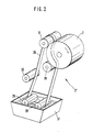
- a cooling roller 9 around which a steel strip of a cooling device is guided, which is not shown in FIG. 1 for reasons of better clarity. Details of this cooling device result from Fig. 2, which will be described in more detail below.
- the feed rollers 6 and 7 are mounted electrically insulated from the machine frame and are equipped with abrasive carbon brushes which rest on each side of the feed roller 6, 7 and are connected to a power source 20 via electrical supply lines 21, 22.
- the current source 20 is, for example, a controllable transformer, and the current flow through the Heating tape 3 for reaching the required tape temperature is regulated via the voltage supplied by the current source 20.
- the total current i fed in is divided into two partial flows from the feed rollers 6 and 7, namely a sealing strand current i S and a return strand current i R.
- the sealing strand current i S electrically heats the sealing strand 24 of the heating tape 3, which has a certain ohmic resistance, which is connected in terms of circuitry in parallel with the ohmic resistance of the return strand 25 of the heating tape 3.
- the electrically resistively heated heating tape 3 applies both the heat to the tubular casing 23 to be sealed and the required sealing pressure.
- the heating tape 3 generally consists of alloy steel, in particular a steel-chromium-nickel alloy with a relatively high electrical resistance.
- the heating tape 3 wraps around the sealing drum 2 at an angle between 180 ° to 270 °, the one feed roller 7 at the starting point of the partial circumference and the other feeding roller 6 at a point on the partial circumference of the sealing drum 2 lies, which corresponds to a wrap angle of the heating tape 3 between 180 ° and 210 °.
- the positions of the two feed rollers 6 and 7 on the partial circumference of the sealing drum 2 can be fixed in position, then the ohmic resistances of the sealing strand 24 and the return strand 25 of the heating tape 3 are designed in relation to one another solely by dimensioning the length of the return strand 25 by one Avoid damage to the anti-adhesive heating tape coating by overheating the heating tape 3 in the return run.
- the cooling roller 9 bears against the sealing drum 2 at the end point of the partial circumference, in which the sealing tube cover 18 is detached from the sealing drum 2. After detachment, the sealed tubular casing 18 is passed over the cooling roller 9.
- the starting material for the production of the sealed tubular casing 18 is a flat film 11, which is located as a roll on a supply roll 12.
- the flat film 11 is fed from the roll winder the supply roll 12 via a possibly necessary, not shown web edge control in a folding device, of which a tubular molded part 17 is indicated schematically in FIG. 1.
- the web edges of the flat film 12 are brought into abutment in the folding device or are formed with an overlap to form the tubular casing 23. Details of such a folding device can be found, for example, in published European patent application 80 120, which goes back to the same applicant as the present application.
- a supply roll 13 for a sealing tape 14 for a sealing tape 14.
- the sealing tape 14 is in contact with the pre-folded from the roll of the supply roll 13 via deflection rolls 15 and 16 brought flat sleeve 23 and together with this the sealing drum 2 supplied.
- the sealing tape 14 covers the overlap or butt seam of the folded hose sleeve 23.
- the pre-folded hose sleeve 23 with the sealing tape 14 placed in position over the butt seam runs between the sealing drum 2 and the heating tape 3.
- the heat and pressure of the heating tape 3 are used to seal the folded tubular casing 23 with the sealing tape 14 to form the sealed tubular casing 18.
- tubular sleeves 23 are to be sealed, one is flat film 11 which is sealable on both sides is necessary, whereby it should be noted that by means of appropriate anti-adhesive coatings, such as by applying a so-called release lacquer layer on the inside edge of the web or the inner web center of the flat film 11, the inside of the folded tubular casing 23 is sealed must be prevented.
- the seam melt of the sealed tubular casing 18 is solidified by the cooling device already mentioned, which has a circumferential cooled steel strip.
- the sealed tube cover 18 is wound up on the spool core of a winding roller 19 via a deflection roller 10 and then fed to further processing.
- a flat film 11 which can be sealed on both sides can be sealed with overlapping web edges even without a sealing tape.
- Material made from a flat film 11 which is sealable on one side is generally pre-folded butt and must then be sealed with the sealing tape 14, which is usually made of the same material as the flat film.
- the heating tape 3 is only slightly wider than the sealing tape 14.
- the sealing layer and thus the sealing tape can be placed inwards or outwards. If the sealing tape is on the inside, it can Avoiding damage to the sealing layer may be advisable to work with anti-adhesive coatings on the back of the sealing tape or on the inner middle of the web in the width of the sealing seam.
- the flat film 11 can be printed on after the roll of the supply roll 12 has run out by means of so-called in-line printing units.
- the processing speed of the flat film 11 to form the sealed tubular casing 18 essentially depends on the dwell time of the flat film under the heating tape and consequently increases as the sealing drum diameter increases.
- sealing or welding speeds of 100 m / min are used.
- the cooling device 27 shows details of the cooling device 27, which has an endlessly rotating steel belt 26, which is guided over the cooling roller 9, a tension roller 32, deflection rollers 28, 29 and 30.
- the deflection roller 30 is close to the one feed roller 6 for the electrical Current of the heating tape 3 arranged.
- the width of the steel strip 26 is slightly larger than the width of the sealing strip 14.
- the width of the cooling roller 9 corresponds approximately to the width of the sealing drum 2.
- Both the steel strip 26 and the heating strip 3 are carried along by the friction on the circumference of the silicone-coated sealing drum 2 and do not have their own drive, only the sealing drum 2 is driven.
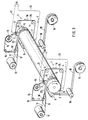
- Fig. 3 shows schematically in perspective a device for a plurality of sealing webs, in which the sealing drum 2 is so wide that e.g. Up to six heating tapes 3 can be placed side by side on the partial circumferential surface of the sealing drum 2.
- the supply rolls 12 for the flat films 11 are partly arranged one above the other and partly next to each other. If there is enough space, all supply rolls can also be arranged side by side or one above the other.
- a similar arrangement as for the supply rolls 12 of the flat films 11 is made for the supply rolls 13 of the sealing tapes 14.
- the flat foils formed into tubular sleeves 23 are formed by means of known means, not shown 11 and the sealing webs lying on the butt or overlapping seams of the tubular casings, lying side by side, are directed onto the partial circumferential surface of the sealing drum 2 and passed under the corresponding number of heated heating tapes 3 pressed against the partial circumferential surface.
- Each heating tape 3 is supplied with power from its own power source.
- the sealed tubular sleeves 18 are guided over the cooling rollers 9 to deflection rollers 10 and from these to winding rollers 19.
- the device according to FIGS. 1 and 3 can also be used to seal flat, unfolded plastic film strips along their band edges that are brought into contact or overlap.
- the structure of the device then changes only to the extent that the folding devices with the tubular molded parts are eliminated.
Landscapes
- Engineering & Computer Science (AREA)
- Mechanical Engineering (AREA)
- Physics & Mathematics (AREA)
- Thermal Sciences (AREA)
- Lining Or Joining Of Plastics Or The Like (AREA)
- Package Closures (AREA)
- Packging For Living Organisms, Food Or Medicinal Products That Are Sensitive To Environmental Conditiond (AREA)
- Developing Agents For Electrophotography (AREA)
- Refuse-Collection Vehicles (AREA)
- Making Paper Articles (AREA)
Abstract
Description
- Die Erfindung betrifft eine Vorrichtung zum kontinuierlichen Schweißen bzw. Siegeln von Nähten von Kunststoff-Folien, mit Vorratsrollen für Flachfolien und für zumindest ein Siegelband.
- Kontinuierlich arbeitende Folienschweiß- oder -siegelmaschinen verwenden umlaufende beheizte Stahlbänder und werden in der Verpackungstechnik beispielsweise zum Siegeln von Kopfnähten an gefüllten Kunststoffbeuteln oder -säcken im Durchlaufverfahren benutzt.
- Bei einer im Stand der Technik bekannten Schweiß- bzw. Siegelmaschine sind zwei endlose Stahlbänder jeweils über zwei Umlenk- bzw. Spannrollen geführt und so angeordnet, daß sie sich in einem der gespannten Strekkenabschnitte zwischen zwei Spannrollen deckungsgleich und flächig berühren. Über die Rollen werden die Bänder in gleicher Richtung angetrieben und fördern die zwischen ihnen befindlichen Folien.
- Zum Aufheizen auf die Siegeltemperatur und zum Aufbringen des Siegeldruckes gleiten auf den Rückseiten der fördernden Stahlbandabschnitte in Förderrichtung feststehende dauerbeheizte Heizelemente, welche die Siegelwärme durch Wärmeleitung über die Stahlbänder auf die miteinander zu siegelnden bzw. zu verschweissenden Folien aufbringen.
- Durch Veränderung der Temperatur und des Anpreßdrucks der Heizelemente, der Fördergeschwindigkeit der Stahlbänder und der Länge der Heizstrecke läßt sich das Siegeln bzw. Schweißen folienspezifisch anpassen.
- Große Nachteile treten jedoch wegen der hohen Gleitreibung zwischen den Heizelementen und den Stahlbändern auf, da die Gleitreibung zu Verschleiß und störendem Abrieb führt. Höhere Siegelgeschwindigkeiten sind im Dauerbetrieb nicht zu erreichen. Nachteilig ist auch die ungleichmäßige spezifische Siegeldruckverteilung, bedingt durch die wegen Temperaturdehnung in den Heizelementen, beispielsweise in Gestalt von Heizbacken, auftretenden Verwerfungen der Wärmeübertragungsgleitflächen. Hieraus resultiert des weiteren eine ungleichförmige Temperaturverteilung in dem einzelnen Stahlband infolge unterschiedlicher Wärmeübertragungswiderstände zwischen den Heizbacken und dem Stahlband.
- Insgesamt gesehen eignen sich die bekannten Schweiß- und Siegelmschinen nicht zum sicheren Herstellen von anspruchsvollen Schweiß- oder Siegelnähten bei höheren Siegelgeschwindigkeiten im Dauerbetrieb.
- Aus der offengelegten europäischen Patentanmeldung 80 120 ist eine Vorrichtung zur Herstellung eines Schlauches aus einer flachen Folienbahn unter Bildung einer Längsnaht bekannt, die einen Formkörper mit einer im Querschnitt im wesentlichen kreiförmigen Innenboh rung zur äußeren Abstützung des geformten Schlauchs im Bereich der gegenseitigen Überlappung der Randzonen der Bahn und einen kreiszylinderförmigen Innendorn zur inneren Abstützung des geformten Schlauchs umfaßt. Des weiteren ist zum Führen und Abstandshalten der Bahnkanten der Folienbahn ein flexibler Streifen vorhanden, der eine im Querschnitt gebogene, in ihrer Krümmung dem Schlauchumfang anpaßbare Form mit einem oder zwei abstehenden Rändern an den Längskanten aufweist. Die Siegelung der mit dieser Vorrichtung hergestellten Schläuche erfolgt im allgemeinen auf einer taktweise arbeitenden Schweiß- bzw. Siegelmaschine, wie sie voranstehend als im Stand der Technik bekannte Maschine beschrieben ist. Durch die taktweise Siegelung ist die Arbeitsgeschwindigkeit derartiger Siegelmaschinen gering und liegt bei etwa 10 m Schlauch pro Minute.
- Zur Herstellung eines Schlauchs aus einer flachen Folienbahn werden üblicherweise Falthilfen, wie Formschultern oder Formköpfe verwendet, wie sie in der DE-A-30 13 320 beschrieben sind, und durch welche die Bahn gebogen und gefaltet wird, so daß sie eine Längsnaht bilden, entlang der eine Verklebung erfolgt. Die beiden Randzonen können auch durch einen Folienstreifen, ein sogenanntes Siegelband, miteinander verbunden werden, wobei es genügt, daß die Randzonen ohne Überlappung aneinanderstoßen.
- In der US-A-2,148,884 ist eine Vorrichtung beschrieben, die einen im Inneren des geformten Schlauchs angeordne ten Dorn zur Abstützung verwendet, während von außen eine Rolle gegen den Schlauch angepreßt wird. Ein exakte Führung der sich überlappenden Randzonen der Bahn ist mit diesen Falthilfen nicht gewährleistet, so daß der gebildete Schlauch keinen gleichmäßigen Umfang besitzt.
- Die aus der US-A-2,856,742 bekannte Formeinrichtung weist zwei einander gegenüberliegende Formteile auf, die sich bogenförmig jeweils auf eine Randzone der Bahn von außen anlegen. Beide Formteile sind im Abstand zueinander in Richtung der Schlauchbahn angeordnet und daher für solche Bahnen nicht geeignet, bei denen auf einer Randzone vor der Schlauchformung ein Klebemittel aufgebracht ist. Die sich überlappenden Randzonen sind nämlich nur im Bereich zwischen den beiden Formteilen voneinander getrennt, so daß die Gefahr besteht, daß die Randzonen bereits vor dem Passieren des ersten Formteils miteinander verkleben.
- In der US-A-2,285,263 ist eine Einrichtung zur Schlauchformung beschrieben, in der die Bahn von innen und außen abgestützt und an ihren Rändern geführt ist. Die äußere Abstützung der Bahn erfolgt durch einen gewölbten Stahlkörper, der die Bahnränder schraubenförmig aneinander annähert. Das Bahnmaterial wird dabei stark mechanisch beansprucht, da die Bahn bei der Schlauchformung bereits vor der Überlappung ihrer Ränder durch den Metallkörper gezwungen wird, eine vorgegebene Form einzunehmen.
- Aufgabe der Erfindung ist es, eine Vorrichtung zu schaffen, die bei wesentlich höheren Schweiß- bzw. Siegelgeschwindigkeiten als bekannte, taktweise arbeitende Vorrichtungen, die kontinuierliche Herstellung von Schweiß- und Siegelnähten an Kunststoff-Folien, bzw. die Herstellung von Schläuchen aus schweiß- bzw. siegelfähigen Kunststoffen ermöglicht.
- Diese Aufgabe wird erfindungsgemäß durch eine Vorrichtung in der Weise gelöst, daß über einen Teilumfang einer Siegeltrommel übereinander gelegte Flachfolien oder zumindest eine zur Schlauchhülle gefaltete Flachfolie mit einem die Überlappungs- bzw. Stoßnaht überdeckenden Siegelband geführt sind und daß zumindest ein endloses Heizband, dessen Breite die Überlappungs- oder Stoßnaht abdeckt, mittels Umlenk- und Spannrollen radial an den Teilumfang der sich drehenden Siegeltrommel angedrückt ist.
- In Ausgestaltung der Erfindung liegen an dem Teilumfang der Siegeltrommel Einspeiserollen für elektrischen Strom zum widerstandsmäßigen Erhitzen des Heizbandes an und sind Schleifkontakte an den Einspeiserollen für die Einspeisung des elektrischen Stroms vorhanden. Zum Zweck der Schweißung bzw. der Siegelung laufen die übereinandergelegten Folien, die sich im Bereich ihrer Längskanten überlappen, bzw. zum Schlauch vorgefaltete Kunststoff-Folienbahnen zwischen dem elektrisch widerstandsmäßig erhitzten Heizband und der Siegeltrommel hindurch.
- Zweckmäßigerweise besteht das Heizband aus legiertem Stahl und umschlingt die Siegeltrommel mit einem Winkel zwischen 180° bis 270°, und ferner liegt die eine Einspeiserolle im Anfangspunkt des Teilumfangs und die andere Einspeiserolle in einem Punkt des Teilumfangs der Siegeltrommel an, der einem Umschlingungswinkel des Heizbandes zwischen 180° und 210° entspricht. Nach der Schweiß- bzw. Siegelung wird der Nahtbereich der Schlauchhülle, der am Umfang der Siegeltrommel anliegt, durch ein Stahlband gekühlt.
- Zur Kühlung der gesiegelten Schlauchhülle liegt eine Kühlwalze im Endpunkt des Teilumfangs an der Siegeltrommel an und es wird die gesiegelte Schlauchhülle nach dem Ablösen von der Siegeltrommel über die Kühlwalze geführt.
- Die weitere Ausgestaltung der Erfindung ergibt sich aus den Ansprüchen 5 bis 13.
- Im folgenden wird die Erfindung anhand von zwei zeichnerisch dargestellten Ausführungsbeispielen näher erläutert.
- Es zeigen:
- Fig. 1 eine schematische perspektivische Ansicht einer Vorrichtung mit einer Siegeltrommel für eine einzelne Siegelbahn, nach der Erfindung,
- Fig. 2 eine Teilansicht einer Kühleinrichtung für die Überlappungs- bzw. Stoßnaht der gesiegelten Schlauchhülle bzw. der im Randbereich sich überlappenden Kunststoff-Folien und
- Fig. 3 eine schematisch perspektivische Ansicht, ähnlich zu Fig. 1, einer Vorrichtung für mehrere Siegelbahnen.
- Die in Fig. 1 dargestellte Siegelvorrichtung 1 besteht aus einer Siegeltrommel 2 bzw. Siegelwalze, einem Heizband 3, das über Umlenk- und Spannrollen 4 und 5 sowie Einspeiserollen 6,7 für elektrischen Strom geführt ist und über einen Teilumfang der Siegeltrommel 2 unter Druck anliegt und Schleifkontakten 8, die zu beiden Seiten der Einspeiserollen 6 und 7 angebracht sind. An der Siegeltrommel 2 liegt des weiteren eine Kühlwalze 9 an, um die ein Stahlband einer Kühleinrichtung herumgeführt ist, die aus Gründen der besseren Übersichtlichkeit in Fig.1 nicht eingezeichnet ist. Einzelheiten dieser Kühleinrichtung ergeben sich aus Fig. 2, die weiter unten noch näher beschrieben werden wird.
- Die Einspeiserollen 6 und 7 sind zum Mschinengestell hin elektrisch isoliert gelagert und mit schleifenden Kohlebürsten ausgerüstet, die zu beiden Seiten an jeder Einspeiserolle 6,7 anliegen und über elektrische Versorgungsleitungen 21,22 mit einer Stromquelle 20 verbunden sind. Die Stromquelle 20 ist beispielsweise ein regelbarer Transformator, und der Stromfluß durch das Heizband 3 zum Erreichen der benötigten Bandtemperatur wird über die von der Stromquelle 20 gelieferte Spannung geregelt. Der eingespeiste Gesamtstrom i teilt sich von den Einspeiserollen 6 und 7 aus in zwei Teilströme, nämlich einen Siegeltrumstrom iS und einen Rücklauftrumstrom iR auf. Der Siegeltrumstrom iS heizt elektrisch das Siegeltrum 24 des Heizbandes 3 auf, das einen bestimmten ohmschen Widerstand besitzt, der schaltungsmäßig parallel mit dem ohmschen Widerstand des Rücklauftrums 25 des Heizbandes 3 liegt. Durch die Bemessung der Längen des Siegeltrums 24 und des Rücklauftrums 25 des Heizbandes 3 besteht die Möglichkeit, die ohmschen Widerstände der beiden Trums zu verändern und somit die Erwärmung in beiden Trums des Heizbandes 3 relativ zueinander abzustimmen, so daß eine zu starke Erhitzung des Rücklauftrums 25, in dem außer Wärmestrahlung keine Wärmeabfuhr erfolgt, vermieden wird und somit eine Schädigung einer gegebenenfalls antiadhäsiven Beschichtung des Heizbandes infolge dieser Überhitzung ausgeschlossen wird. Das elektrisch widerstandsmäßig erhitzte Heizband 3 bringt sowohl die Wärme auf die zu siegelnde Schlauchhülle 23 als auch den erforderlichen Siegeldruck auf. Das Heizband 3 besteht im allgemeinen aus legiertem Stahl, insbesondere einer Stahl-Chrom-Nickel-Legierung mit relativ großem elektrischem Widerstand. Das Heizband 3 umschlingt die Siegeltrommel 2 mit einem Winkel zwischen 180° bis 270°, wobei die eine Einspeiserolle 7 im Anfangspunkt des Teilumfangs und die andere Einspeiserolle 6 in einem Punkt des Teilumfangs der Siegeltrommel 2 an liegt, der einem Umschlingungswinkel des Heizbandes 3 zwischen 180° und 210° entspricht. Die Positionen der beiden Einspeiserollen 6 und 7 am Teilumfang der Siegeltrommel 2 können lagefest sein, es werden dann die ohmschen Widerstände des Siegeltrums 24 und des Rücklauftrums 25 des Heizbandes 3 in ihrem Verhältnis zueinander alleine durch die Bemessung der Länge des Rücklauftrums 25 ausgelegt, um eine Schädigung der antiadhäsiven Heizbandbeschichtung durch Überhitzen des Heizbandes 3 im Rücklauftrum zu vermeiden. Es besteht auch die Möglichkeit, obgleich dies zeichnerisch nicht dargestellt ist, die Position einer oder der beiden Einspeiserollen 6,7 entlang dem Teilumfang der Siegeltrommel 2 einzustellen, um die Längen des Siegeltrums 24 und des Rücklauftrums 25 des Heizbandes 3 zu verändern und somit den elektrischen Widerstand und die Erwärmung im Rücklauftrum 25 so auszulegen, daß keine Schädigung der antiadhäsiven Kunststoffbeschichtung des Heizbandes durch Überhitzen auftritt.
- Die Kühlwalze 9 liegt in dem Endpunkt des Teilumfangs an der Siegeltrommel 2 an, in welchem die Siegelschlauchhülle 18 von der Siegeltrommel 2 abgelöst wird. Nach dem Ablösen wird die gesiegelte Schlauchhülle 18 über die Kühlwalze 9 geführt.
- Das Ausgangsmaterial für die Herstellung der gesiegelten Schlauchhülle 18 ist eine Flachfolie 11, die sich als Wickel auf einer Vorratsrolle 12 befindet. Die Zuführung der Flachfolie 11 erfolgt von dem Rollenwickel der Vorratsrolle 12 über eine gegebenenfalls erforderliche, nicht dargestellte Bahnkantensteuerung in eine Faltvorrichtung, von der schematisch ein Schlauchformteil 17 in Fig. 1 angedeutet ist. In der Faltvorrichtung werden die Bahnkanten der Flachfolie 12 auf Stoß gebracht oder mit Überlappung zu der Schlauchhülle 23 geformt. Einzelheiten einer derartigen Faltvorrichtung sind beispielsweise der offengelegten europäischen Patentanmeldung 80 120 zu entnehmen, die auf die gleiche Anmelderin wie die vorliegende Anmeldung zurückgeht.
- Oberhalb der Bahn der gefalteten bzw. geformten Schlauchhülle 23, die nach dem Verlassen der Faltvorrichtung flach liegt, befindet sich eine Vorratsrolle 13 für ein Siegelband 14. Das Siegelband 14 wird von dem Rollenwickel der Vorratsrolle 13 über Umlenkrollen 15 und 16 in Kontakt mit der vorgefalteten flachgelegten Schlauchhülle 23 gebracht und gemeinsam mit dieser der Siegeltrommel 2 zugeführt. Das Siegelband 14 überdeckt die Überlappungs- bzw. Stoßnaht der gefalteten Schlauchhülle 23. Nach der Faltvorrichtung läuft die vorgefaltete Schlauchhülle 23 mit dem in seine Lage über der Stoßnaht gebrachten Siegelband 14 zwischen der Siegeltrommel 2 und dem Heizband 3 hindurch. Durch die Wärme und den Druck des Heizbandes 3 erfolgt die Siegelung der gefalteten Schlauchhülle 23 mit dem Siegelband 14 zu der gesiegelten Schlauchhülle 18.
- Bei überlappt zu siegelnden Schlauchhüllen 23 ist eine beidseitig siegelfähige Flachfolie 11 erforderlich, wobei zu beachten ist, daß durch entsprechende antiadhäsive Beschichtungen, wie etwa durch den Antrag einer sogenannten Release-Lackschicht auf den innen zu liegen kommenden Bahnrand oder auf die innere Bahnmitte der Flachfolie 11 ein Zusammensiegeln der Innenseite der gefalteten Schlauchhülle 23 verhindert werden muß.
- Auf dem Restumfang der Siegeltrommel 2 zwischen der einen Einspeiserolle 6 und der an der Siegeltrommel 2 anliegenden Kühlwalze 9 wird die Nahtschmelze der gesiegelten Schlauchhülle 18 durch die schon erwähnte Kühleinrichtung, die ein umlaufendes gekühltes Stahlband aufweist, zum Erstarren gebracht. Von der Kühlwalze 9 wird die gesiegelte Schlauchhülle 18 über eine Umlenkwalze 10 auf dem Spulenkern einer Aufwickelrolle 19 aufgewickelt und danach der Weiterverarbeitung zugeführt. Eine beidseitig siegelfähige Flachfolie 11 kann mit überlappenden Bahnkanten auch ohne Siegelband gesiegelt werden. Material aus einer einseitig siegelfähigen Flachfolie 11 wird im allgemeinen auf Stoß vorgefaltet und muß dann mit dem Siegelband 14, das meist aus dem gleichen Material wie die Flachfolie hergestellt ist, gesiegelt werden. Das Heizband 3 ist nur geringfügig breiter als das Siegelband 14.
- Je nach Verwendungszweck kann die Siegelschicht und somit das Siegelband nach innen oder nach außen gelegt werden. Bei innen liegendem Siegelband kann es zur Vermeidung von Siegelschichtbeschädigungen zweckmäßig sein, mit antiadhäsiven Beschichtungen auf der Rückseite des Siegelbandes oder auf der inneren Bahnmitte in Siegelnahtbreite zu arbeiten.
- Die Vermeidung einer Überhitzung des Heizbandes 3 ist insbesondere dann wichtig, wenn aus siegeltechnischen Gründen mit einem auf der Siegelseite antiadhäsiv beschichteten Heizband 3 gesiegelt werden muß.
- Es sei noch erwähnt, daß zwecks werbewirksamer Schlauchhüllenausstattung die Flachfolie 11 nach dem Ablauf vom Rollenwickel der Vorratsrolle 12 mittels sogenannter In-line geschalteter Druckwerke bedruckt werden kann.
- Die Verarbeitungsgeschwindigkeit der Flachfolie 11 zu der gesiegelten Schlauchhülle 18 hängt im wesentlichen von der Verweilzeit der Flachfolie unter dem Heizband ab und steigt demzufolge mit zunehmendem Siegeltrommeldurchmesser.
- In der Praxis werden Siegel- oder Schweißgeschwindigkeiten von 100 m/min gefahren.
- In Fig. 2 sind Einzelheiten der Kühleinrichtung 27 gezeigt, die ein endlos umlaufendes Stahlband 26 aufweist, das über die Kühlwalze 9, eine Spannrolle 32, Umlenkrollen 28,29 und 30 geführt ist. Die Umlenkrolle 30 ist nahe der einen Einspeiserolle 6 für den elektrischen Strom des Heizbandes 3 angeordnet. Unterhalb der beiden Umlenkrollen 28 und 29 befindet sich eine Kühlwanne 31, die beispielsweise mit Wasser oder einer sonstigen geeigneten Kühlflüssigkeit gefüllt ist. Die Breite des Stahlbandes 26 ist geringfügig größer als die Breite des Siegelbandes 14. Die Breite der Kühlwalze 9 entspricht in etwa der Breite der Siegeltrommel 2.
- Sowohl das Stahlband 26 als auch das Heizband 3 werden durch die Reibung am Umschlingungsumfang der silikonbeschichteten Siegeltrommel 2 mitgeführt und besitzen keinen eigenen Antrieb, nur die Siegeltrommel 2 wird angetrieben.
- Fig. 3 zeigt schematisch in perspektivischer Darstellung eine Vorrichtung für mehrere Siegelbahnen, bei der die Siegeltrommel 2 so breit ausgebildet ist, daß z.B. bis zu sechs Heizbänder 3 nebeneinander auf der Teilumfangsfläche der Siegeltrommel 2 Platz haben. Die Vorratsrollen 12 für die Flachfolien 11 sind zum Teil übereinander und zum Teil nebeneinander angeordnet. Falls genügend Platz vorhanden ist, können auch alle Vorratsrollen nebeneinander oder übereinander angeordnet werden. Eine ähnliche Anordnung wie für die Vorratsrollen 12 der Flachfolien 11 ist für die Vorratsrollen 13 der Siegelbänder 14 getroffen.
- Durch an sich bekannte, nicht gezeigte Einrichtungen werden die zu Schlauchhüllen 23 geformten Flachfolien 11 und die auf die Stoß- bzw. Überlappungsnähten der Schlauchhüllen aufliegenden Siegelbahnen nebeneinander liegend auf die Teilumfangsfläche der Siegeltrommel 2 gelenkt und unter der entsprechenden Anzahl von aufgeheizten und an die Teilumfangsfläche angedrückte Heizbänder 3 hindurchgeführt. Jedes Heizband 3 wird von einer eigenen Stromquelle mit Strom beliefert. Es sind soviele Kühlwalzen 9 wie Stahlbänder 26 zu Kühlzwecken vorhanden, die über die gesiegelten Schlauchhüllen 18 geführt sind, wobei die endlos umlaufenden Stahlbänder durch eine gemeinsame Kühlwanne 31 hindurchlaufen. Die gesiegelten Schlauchhüllen 18 sind über die Kühlwalzen 9 zu Umlenkwalzen 10 und von diesen zu Aufwickelrollen 19 geführt.
- Obwohl dies nicht gezeigt ist, können mit der Vorrichtung nach Fig. 1 bzw. 3 auch flache, nicht gefaltete Kunststoff-Folienbänder entlang ihrer auf Stoß gebrachten oder sich überlappenden Bandkanten miteinander versiegelt werden. Der Aufbau der Vorrichtung ändert sich dann nur insoweit als daß die Falteinrichtungen mit den Schlauchformteilen entfallen.
Claims (13)
Priority Applications (1)
| Application Number | Priority Date | Filing Date | Title |
|---|---|---|---|
| AT86116118T ATE46480T1 (de) | 1985-11-29 | 1986-11-21 | Vorrichtung zum kontinuierlichen schweissen bzw. siegeln von naehten von kunststoff-folien. |
Applications Claiming Priority (2)
| Application Number | Priority Date | Filing Date | Title |
|---|---|---|---|
| DE19853542256 DE3542256A1 (de) | 1985-11-29 | 1985-11-29 | Vorrichtung zum kontinuierlichen schweissen bzw. siegeln von naehten von kunststoff-folien |
| DE3542256 | 1985-11-29 |
Publications (2)
| Publication Number | Publication Date |
|---|---|
| EP0224808A1 true EP0224808A1 (de) | 1987-06-10 |
| EP0224808B1 EP0224808B1 (de) | 1989-09-20 |
Family
ID=6287197
Family Applications (1)
| Application Number | Title | Priority Date | Filing Date |
|---|---|---|---|
| EP86116118A Expired EP0224808B1 (de) | 1985-11-29 | 1986-11-21 | Vorrichtung zum kontinuierlichen Schweissen bzw. Siegeln von Nähten von Kunststoff-Folien |
Country Status (7)
| Country | Link |
|---|---|
| US (1) | US4746391A (de) |
| EP (1) | EP0224808B1 (de) |
| JP (1) | JPS62253433A (de) |
| AT (1) | ATE46480T1 (de) |
| CA (1) | CA1286580C (de) |
| DE (2) | DE3542256A1 (de) |
| FI (1) | FI88594C (de) |
Cited By (6)
| Publication number | Priority date | Publication date | Assignee | Title |
|---|---|---|---|---|
| EP0337244A3 (en) * | 1988-04-13 | 1990-08-29 | Hoechst Aktiengesellschaft | Tubular casing, especially artificial sausage casing, with longitudinal adhesive tape |
| EP0302996A3 (de) * | 1987-08-11 | 1991-03-13 | Paper Converting Machine GmbH | Vorrichtung zurm Längsnahtschweissen von Kunststoffolien |
| EP0467037A3 (en) * | 1990-06-29 | 1993-08-18 | G.M. Pfaff Aktiengesellschaft | Method and apparatus for welding of thermoplastic webs |
| EP0569807A1 (de) * | 1992-05-14 | 1993-11-18 | Focke & Co. (GmbH & Co.) | Vorrichtung zum Verbinden eines Aufreissstreifens mit einer Materialbahn |
| EP1905570A1 (de) * | 2006-09-28 | 2008-04-02 | Aisapack Holding SA | Verfahren und Vorrichtung zum internen Schweissen von Kunststoffrohren |
| WO2012093112A1 (de) * | 2011-01-07 | 2012-07-12 | Packsys Global (Switzerland) Ltd. | Vorrichtung und verfahren zur herstellung von tubenrohren für verpackungstuben |
Families Citing this family (17)
| Publication number | Priority date | Publication date | Assignee | Title |
|---|---|---|---|---|
| US4822437A (en) * | 1988-02-19 | 1989-04-18 | Mobil Oil Corporation | Method and apparatus for making non-roping thermoplastic draw tape for thermoplastic bags |
| US4895611A (en) * | 1988-02-19 | 1990-01-23 | Mobil Oil Corporation | Method and apparatus for making non-roping thermoplastic draw tape for thermplastic bags |
| US5024642A (en) * | 1988-12-05 | 1991-06-18 | Presto Products, Incorporated | Rotary draw tape bag making apparatus and method |
| ATE154800T1 (de) * | 1992-08-25 | 1997-07-15 | Searle & Co | N-(alkanoylamino-2-hydroxypropyl)-sulfonamide verwendbar als retrovirale proteaseninhibitoren |
| DE19619558A1 (de) * | 1996-05-14 | 1997-11-20 | Focke & Co | Vorrichtung zum Verbinden eines Aufreißstreifens mit einer Folienbahn |
| US5935379A (en) * | 1998-02-27 | 1999-08-10 | E. I. Du Pont De Nemours And Company | Heat-sealing wheels for forming a longitudinal weld or seal in seams of plastic films |
| IT1304457B1 (it) * | 1998-07-24 | 2001-03-19 | Gd Spa | Dispositivo di saldatura di un nastrino a strappo ad un nastro. |
| US6059458A (en) * | 1999-02-05 | 2000-05-09 | Tenneco Packaging, Inc. | Elastic top drawtape bag and method of manufacturing the same |
| US6328922B1 (en) * | 1999-10-28 | 2001-12-11 | Xerox Corporation | Process for post treatment of a flexible imaging member belt |
| US6402377B1 (en) | 2000-05-22 | 2002-06-11 | Pactiv Corporation | Non-blocking elastomeric articles |
| US20030010439A1 (en) * | 2001-07-16 | 2003-01-16 | Fenton Jay Thomas | Seam sealing apparatus and process therefor |
| US7077796B2 (en) * | 2003-03-28 | 2006-07-18 | The Glad Products Company | Bag with elastic strip and method of making the same |
| TWM291358U (en) * | 2005-11-10 | 2006-06-01 | Guang-Shiung Wu | Improvement for attaching structure of the corrugated paper machine |
| ATE496759T1 (de) * | 2006-04-06 | 2011-02-15 | Aisapack Holding Sa | Schlauchförmiger verpackungskörper aus thermoplastmaterial mit eingebettetem streifen |
| US9296171B2 (en) * | 2008-03-11 | 2016-03-29 | Frito-Lay North America, Inc. | Method for making a flat bottom pillow pouch |
| CN109648838A (zh) * | 2018-12-03 | 2019-04-19 | 上海博应信息技术有限公司 | 一种柔性材料折边覆膜机构 |
| EP4122834B1 (de) * | 2020-03-16 | 2025-12-10 | Yakult Honsha Co., Ltd. | Heisssiegelvorrichtung |
Citations (5)
| Publication number | Priority date | Publication date | Assignee | Title |
|---|---|---|---|---|
| US3257257A (en) * | 1962-09-15 | 1966-06-21 | Heimbach Gmbh Thomas Josef | Seam welding apparatus |
| US3314591A (en) * | 1966-02-16 | 1967-04-18 | Reynolds Metals Co | Pouch construction |
| DE1938568A1 (de) * | 1969-07-29 | 1971-02-25 | Windmoeller & Hoelscher | Schlauchbildevorrichtung zur Herstellung von Schlaeuchen aus mindestens einseitig aus thermoplastischem Kunststoff bestehenden Werkstoffbahnen |
| DE2423321A1 (de) * | 1974-05-14 | 1975-11-27 | Kiefel Koerting Gmbh | Konstinuierliche schweissvorrichtung fuer thermoplastische oder teilthermoplastische folien |
| DE2907849A1 (de) * | 1978-03-03 | 1979-09-06 | Toyo Syokuhin Kikai Kk | Verpackungsmaschine |
Family Cites Families (9)
| Publication number | Priority date | Publication date | Assignee | Title |
|---|---|---|---|---|
| US2285263A (en) * | 1942-06-02 | Forming tool | ||
| US2148884A (en) * | 1935-06-05 | 1939-02-28 | Ind Patents Corp | Method for forming synthetic sausage casings |
| US2556008A (en) * | 1948-12-28 | 1951-06-05 | William F Stahl | Plastic-sealing apparatus |
| US2856742A (en) * | 1954-12-27 | 1958-10-21 | American Viscose Corp | Guide for sausage stuffing machine |
| US3208898A (en) * | 1960-03-09 | 1965-09-28 | Sealed Air Corp | Apparatus for embossing and laminating materials |
| US3829341A (en) * | 1972-10-13 | 1974-08-13 | Solidyne Inc | Dielectric sealing apparatus |
| US4057456A (en) * | 1976-03-15 | 1977-11-08 | Hasbro Industries, Inc. | Apparatus for trimming an extrudate |
| DE3013320A1 (de) * | 1980-04-05 | 1981-10-15 | Hoechst Ag, 6000 Frankfurt | Fuer lebensmittel, insbesondere wurstwaren geeignete schlauchhuelle mit einer klebenaht und verfahren zu ihrer herstellung |
| DE3145967A1 (de) * | 1981-11-20 | 1983-06-01 | Hoechst Ag, 6230 Frankfurt | Verfahren und vorrichtung zur bildung eines schlauches aus einer flachen bahn |
-
1985
- 1985-11-29 DE DE19853542256 patent/DE3542256A1/de not_active Withdrawn
-
1986
- 1986-11-21 AT AT86116118T patent/ATE46480T1/de not_active IP Right Cessation
- 1986-11-21 EP EP86116118A patent/EP0224808B1/de not_active Expired
- 1986-11-21 DE DE8686116118T patent/DE3665693D1/de not_active Expired
- 1986-11-27 FI FI864840A patent/FI88594C/fi not_active IP Right Cessation
- 1986-11-28 CA CA000524052A patent/CA1286580C/en not_active Expired - Fee Related
- 1986-11-28 JP JP61282208A patent/JPS62253433A/ja active Pending
- 1986-12-01 US US06/936,384 patent/US4746391A/en not_active Expired - Lifetime
Patent Citations (5)
| Publication number | Priority date | Publication date | Assignee | Title |
|---|---|---|---|---|
| US3257257A (en) * | 1962-09-15 | 1966-06-21 | Heimbach Gmbh Thomas Josef | Seam welding apparatus |
| US3314591A (en) * | 1966-02-16 | 1967-04-18 | Reynolds Metals Co | Pouch construction |
| DE1938568A1 (de) * | 1969-07-29 | 1971-02-25 | Windmoeller & Hoelscher | Schlauchbildevorrichtung zur Herstellung von Schlaeuchen aus mindestens einseitig aus thermoplastischem Kunststoff bestehenden Werkstoffbahnen |
| DE2423321A1 (de) * | 1974-05-14 | 1975-11-27 | Kiefel Koerting Gmbh | Konstinuierliche schweissvorrichtung fuer thermoplastische oder teilthermoplastische folien |
| DE2907849A1 (de) * | 1978-03-03 | 1979-09-06 | Toyo Syokuhin Kikai Kk | Verpackungsmaschine |
Cited By (11)
| Publication number | Priority date | Publication date | Assignee | Title |
|---|---|---|---|---|
| EP0302996A3 (de) * | 1987-08-11 | 1991-03-13 | Paper Converting Machine GmbH | Vorrichtung zurm Längsnahtschweissen von Kunststoffolien |
| EP0337244A3 (en) * | 1988-04-13 | 1990-08-29 | Hoechst Aktiengesellschaft | Tubular casing, especially artificial sausage casing, with longitudinal adhesive tape |
| EP0467037A3 (en) * | 1990-06-29 | 1993-08-18 | G.M. Pfaff Aktiengesellschaft | Method and apparatus for welding of thermoplastic webs |
| EP0569807A1 (de) * | 1992-05-14 | 1993-11-18 | Focke & Co. (GmbH & Co.) | Vorrichtung zum Verbinden eines Aufreissstreifens mit einer Materialbahn |
| US5411625A (en) * | 1992-05-14 | 1995-05-02 | Focke & Co. (Gmbh & Co.) | Apparatus for bonding a tear tape to a web of material |
| EP1905570A1 (de) * | 2006-09-28 | 2008-04-02 | Aisapack Holding SA | Verfahren und Vorrichtung zum internen Schweissen von Kunststoffrohren |
| WO2008038206A3 (fr) * | 2006-09-28 | 2008-06-19 | Aisapack Holding Sa | Procede et dispositif de soudage interieur de tubes en matiere plastique |
| RU2438871C2 (ru) * | 2006-09-28 | 2012-01-10 | Айзапак Холдинг С.А. | Способ и устройство для сварки пластиковых туб изнутри |
| CN101522394B (zh) * | 2006-09-28 | 2012-04-04 | 艾萨帕克控股公司 | 塑料管内部焊接工艺及设备 |
| US8157941B2 (en) | 2006-09-28 | 2012-04-17 | Aisapack Holding S.A. | Process for the internal welding of plastic tubes |
| WO2012093112A1 (de) * | 2011-01-07 | 2012-07-12 | Packsys Global (Switzerland) Ltd. | Vorrichtung und verfahren zur herstellung von tubenrohren für verpackungstuben |
Also Published As
| Publication number | Publication date |
|---|---|
| CA1286580C (en) | 1991-07-23 |
| EP0224808B1 (de) | 1989-09-20 |
| DE3665693D1 (en) | 1989-10-26 |
| FI88594C (fi) | 1993-06-10 |
| ATE46480T1 (de) | 1989-10-15 |
| FI864840A0 (fi) | 1986-11-27 |
| FI88594B (fi) | 1993-02-26 |
| US4746391A (en) | 1988-05-24 |
| DE3542256A1 (de) | 1987-06-04 |
| JPS62253433A (ja) | 1987-11-05 |
| FI864840L (fi) | 1987-05-30 |
Similar Documents
| Publication | Publication Date | Title |
|---|---|---|
| EP0224808B1 (de) | Vorrichtung zum kontinuierlichen Schweissen bzw. Siegeln von Nähten von Kunststoff-Folien | |
| DE68918268T2 (de) | Hochgeschwindigkeits-kontaktschweissgerät. | |
| DE69319730T2 (de) | Vorrichtung zum verstellen von Antriebsaggregaten für Folien in einer Schlauchfolienherstellungsmaschine | |
| DE1479930B1 (de) | Verfahren und vorrichtung zum kontinuierlichen herstellen eines rohres aus einer flachen bahn eines biegsamen, schweissbaren materials | |
| DE4024922A1 (de) | Verfahren und einrichtung zum doppelseitigen laminieren eines gegenstandes | |
| EP0710538B1 (de) | Vorrichtung zur Bildung einer Längsnaht eines Folienschlauches | |
| DE2908341A1 (de) | Wickelkern, verfahren zu seiner herstellung, verfahren zum wickeln einer materialbahn unter verwendung des wickelkerns und dafuer geeignete vorrichtung | |
| DE2123200A1 (de) | ||
| DE1479852A1 (de) | Geraet zum fortlaufenden Verschweissen und Abtrennen,insbesondere von Folien durch Waermeeinwirkung | |
| DE1679978C3 (de) | Vorrichtung zum linearen Verschweissen von zwei Lagen eines thermoplastischen oder thermoplastisch beschichteten Materials | |
| DE202018104342U1 (de) | Verpackungsmaschine | |
| DE3317610A1 (de) | Kombinierte vorrichtung zur erzeugung von rohrfoermigen kunststoffhuellen zum aufbringen auf behaelter | |
| EP0812257B1 (de) | Verfahren und vorrichtung zum beheizen einer bewegten bahn, insbesondere wellpappenbahn | |
| DE69731280T2 (de) | Versiegelungsvorrichtung | |
| CH658419A5 (de) | Verfahren zum elektrischen widerstands-rollennahtschweissen und schweissmaschine zum durchfuehren des verfahrens. | |
| EP0538757A1 (de) | Verfahren zum Verpacken von Gewebeballen in eine Schutzfolie und Vorrichtung zur Durchführung des Verfahrens | |
| DE2355847A1 (de) | Verfahren und vorrichtung zur herstellung biegsamer rohre mit drahteinlage | |
| CH620153A5 (de) | ||
| EP0271800A1 (de) | Transportvorrichtung, insbesondere für Falzprodukte | |
| DE102012003835A1 (de) | Vorrichtung und Verfahren zur Herstellung eines Folienschlauches | |
| DE4324337C2 (de) | Wiederbefeuchtungseinrichtung für eine bedruckte Papierbahn | |
| DE1479930C (de) | Verfahren und Vorrichtung zum kontinuierlichen Herstellen eines Rohres aus einer flachen Bahn eines biegsamen, schweißbaren Materials | |
| DE2224317B1 (de) | Schweisszylinder zum verschweissen von ueber den schweisszylinder herumgefuehrten folienbahnen aus thermoplastischen kunststoffen | |
| DE4442047C2 (de) | Verfahren zum kontinuierlichen Verschweißen von Kunststoffolien, insbesondere auch von mehrschichtigen Laminatfolien mit einer Sperrschicht aus Kunststoff, und Vorrichtung zur Durchführung des Verfahrens | |
| DE2359705C3 (de) | Maschine zum Umhüllen von Gegenständen |
Legal Events
| Date | Code | Title | Description |
|---|---|---|---|
| PUAI | Public reference made under article 153(3) epc to a published international application that has entered the european phase |
Free format text: ORIGINAL CODE: 0009012 |
|
| AK | Designated contracting states |
Kind code of ref document: A1 Designated state(s): AT BE CH DE FR GB IT LI NL SE |
|
| 17P | Request for examination filed |
Effective date: 19870918 |
|
| 17Q | First examination report despatched |
Effective date: 19880205 |
|
| GRAA | (expected) grant |
Free format text: ORIGINAL CODE: 0009210 |
|
| AK | Designated contracting states |
Kind code of ref document: B1 Designated state(s): AT BE CH DE FR GB IT LI NL SE |
|
| REF | Corresponds to: |
Ref document number: 46480 Country of ref document: AT Date of ref document: 19891015 Kind code of ref document: T |
|
| REF | Corresponds to: |
Ref document number: 3665693 Country of ref document: DE Date of ref document: 19891026 |
|
| ITF | It: translation for a ep patent filed | ||
| ET | Fr: translation filed | ||
| GBT | Gb: translation of ep patent filed (gb section 77(6)(a)/1977) | ||
| PLBE | No opposition filed within time limit |
Free format text: ORIGINAL CODE: 0009261 |
|
| STAA | Information on the status of an ep patent application or granted ep patent |
Free format text: STATUS: NO OPPOSITION FILED WITHIN TIME LIMIT |
|
| 26N | No opposition filed | ||
| ITTA | It: last paid annual fee | ||
| EAL | Se: european patent in force in sweden |
Ref document number: 86116118.0 |
|
| REG | Reference to a national code |
Ref country code: GB Ref legal event code: IF02 |
|
| PGFP | Annual fee paid to national office [announced via postgrant information from national office to epo] |
Ref country code: SE Payment date: 20031105 Year of fee payment: 18 Ref country code: NL Payment date: 20031105 Year of fee payment: 18 |
|
| PGFP | Annual fee paid to national office [announced via postgrant information from national office to epo] |
Ref country code: FR Payment date: 20031110 Year of fee payment: 18 |
|
| PGFP | Annual fee paid to national office [announced via postgrant information from national office to epo] |
Ref country code: AT Payment date: 20031112 Year of fee payment: 18 |
|
| PGFP | Annual fee paid to national office [announced via postgrant information from national office to epo] |
Ref country code: GB Payment date: 20031119 Year of fee payment: 18 |
|
| PGFP | Annual fee paid to national office [announced via postgrant information from national office to epo] |
Ref country code: CH Payment date: 20031128 Year of fee payment: 18 |
|
| PGFP | Annual fee paid to national office [announced via postgrant information from national office to epo] |
Ref country code: DE Payment date: 20031130 Year of fee payment: 18 |
|
| PGFP | Annual fee paid to national office [announced via postgrant information from national office to epo] |
Ref country code: BE Payment date: 20040121 Year of fee payment: 18 |
|
| PG25 | Lapsed in a contracting state [announced via postgrant information from national office to epo] |
Ref country code: GB Free format text: LAPSE BECAUSE OF NON-PAYMENT OF DUE FEES Effective date: 20041121 Ref country code: AT Free format text: LAPSE BECAUSE OF NON-PAYMENT OF DUE FEES Effective date: 20041121 |
|
| PG25 | Lapsed in a contracting state [announced via postgrant information from national office to epo] |
Ref country code: SE Free format text: LAPSE BECAUSE OF NON-PAYMENT OF DUE FEES Effective date: 20041122 |
|
| PG25 | Lapsed in a contracting state [announced via postgrant information from national office to epo] |
Ref country code: LI Free format text: LAPSE BECAUSE OF NON-PAYMENT OF DUE FEES Effective date: 20041130 Ref country code: CH Free format text: LAPSE BECAUSE OF NON-PAYMENT OF DUE FEES Effective date: 20041130 Ref country code: BE Free format text: LAPSE BECAUSE OF NON-PAYMENT OF DUE FEES Effective date: 20041130 |
|
| BERE | Be: lapsed |
Owner name: *HOECHST A.G. Effective date: 20041130 |
|
| PG25 | Lapsed in a contracting state [announced via postgrant information from national office to epo] |
Ref country code: NL Free format text: LAPSE BECAUSE OF NON-PAYMENT OF DUE FEES Effective date: 20050601 Ref country code: DE Free format text: LAPSE BECAUSE OF NON-PAYMENT OF DUE FEES Effective date: 20050601 |
|
| EUG | Se: european patent has lapsed | ||
| GBPC | Gb: european patent ceased through non-payment of renewal fee |
Effective date: 20041121 |
|
| REG | Reference to a national code |
Ref country code: CH Ref legal event code: PL |
|
| PG25 | Lapsed in a contracting state [announced via postgrant information from national office to epo] |
Ref country code: FR Free format text: LAPSE BECAUSE OF NON-PAYMENT OF DUE FEES Effective date: 20050729 |
|
| NLV4 | Nl: lapsed or anulled due to non-payment of the annual fee |
Effective date: 20050601 |
|
| REG | Reference to a national code |
Ref country code: FR Ref legal event code: ST |
|
| PG25 | Lapsed in a contracting state [announced via postgrant information from national office to epo] |
Ref country code: IT Free format text: LAPSE BECAUSE OF NON-PAYMENT OF DUE FEES;WARNING: LAPSES OF ITALIAN PATENTS WITH EFFECTIVE DATE BEFORE 2007 MAY HAVE OCCURRED AT ANY TIME BEFORE 2007. THE CORRECT EFFECTIVE DATE MAY BE DIFFERENT FROM THE ONE RECORDED. Effective date: 20051121 |
|
| BERE | Be: lapsed |
Owner name: *HOECHST A.G. Effective date: 20041130 |