EP0224863B1 - Fermeture avec moyens d'aération intégrés - Google Patents
Fermeture avec moyens d'aération intégrés Download PDFInfo
- Publication number
- EP0224863B1 EP0224863B1 EP86116414A EP86116414A EP0224863B1 EP 0224863 B1 EP0224863 B1 EP 0224863B1 EP 86116414 A EP86116414 A EP 86116414A EP 86116414 A EP86116414 A EP 86116414A EP 0224863 B1 EP0224863 B1 EP 0224863B1
- Authority
- EP
- European Patent Office
- Prior art keywords
- pourer
- ventilation
- bellows
- closure member
- container
- Prior art date
- Legal status (The legal status is an assumption and is not a legal conclusion. Google has not performed a legal analysis and makes no representation as to the accuracy of the status listed.)
- Expired - Lifetime
Links
Images



Classifications
-
- B—PERFORMING OPERATIONS; TRANSPORTING
- B65—CONVEYING; PACKING; STORING; HANDLING THIN OR FILAMENTARY MATERIAL
- B65D—CONTAINERS FOR STORAGE OR TRANSPORT OF ARTICLES OR MATERIALS, e.g. BAGS, BARRELS, BOTTLES, BOXES, CANS, CARTONS, CRATES, DRUMS, JARS, TANKS, HOPPERS, FORWARDING CONTAINERS; ACCESSORIES, CLOSURES, OR FITTINGS THEREFOR; PACKAGING ELEMENTS; PACKAGES
- B65D47/00—Closures with filling and discharging, or with discharging, devices
- B65D47/04—Closures with discharging devices other than pumps
- B65D47/06—Closures with discharging devices other than pumps with pouring spouts or tubes; with discharge nozzles or passages
- B65D47/061—Closures with discharging devices other than pumps with pouring spouts or tubes; with discharge nozzles or passages with telescopic, retractable or reversible spouts, tubes or nozzles
Definitions
- the invention relates to a closure with integrated ventilation for metal or plastic containers, with a plastic ring attachable to the container opening with a pouring spout and with at least one ventilation channel, which is arranged at least partially in the region of the pouring spout and extends at least over part of the length of the pouring spout , wherein the ventilation channel or its walls are integrally connected to the pouring spout, the ventilation channel is annular and its walls defining it are an inner and an outer cylinder jacket, which are connected to form a double tube at the lower end facing the container interior, and wherein Ventilation openings are arranged in the lower region of the double pipe.
- the ventilation channel has the sense of simultaneously allowing air to flow into the interior of the container while pouring liquid out of a container, so that a strong "breathing" of the canister when pouring out the filling material, that is to say a brief interruption of the liquid jet when air flows in and intermittent reinstallation of the liquid jet is omitted.
- the annular ventilation channel extends only a short distance from the end of the pouring spout inside the container into the pouring spout, while the pouring spout itself is relatively long.
- This has the disadvantage that, in particular when pouring liquids with a higher viscosity than water, for example oil, the entire cross section of the pouring spout is nevertheless filled with liquid, so that air cannot penetrate continuously into the ventilation duct.
- a closure is known from US Pat. No. 2,898,014, in which a ventilation channel runs along the entire length of the pouring spout. However, this has the disadvantage that the ventilation channel is attached to the pouring spout on one side.
- the closure has to be inserted into the container neck in a certain, fixed orientation and in such a way that when liquid is poured out of the pouring spout, the ventilation channel is as high as possible. Otherwise, it can happen that liquid penetrates into the ventilation channel and also flows out of it, so that it is robbed of its function.
- Closures with ventilation channels that are otherwise commercially available are either only very complex and expensive to manufacture or are not fully functional in the desired manner.
- the present invention has for its object to improve a closure with the features mentioned so that it is easy to manufacture on the one hand and on the other hand works safely in any position and orientation and in all cases ensures the inflow of air when pouring liquid .
- the ventilation channel extends over most of the length of the pouring spout, the ventilation openings in the outer cylinder jacket are recessed, the pouring spout is formed by the inner cylinder jacket and the plastic ring is designed as an insert which can be inserted into the container opening and is in one piece with the pouring spout.
- the one-piece design of the entire closure consisting of the as Insert ring designed plastic ring and the double tube, with ventilation openings only recessed on the outer cylinder jacket and an annular ventilation duct concentric with the central pouring spout, enables relatively simple and inexpensive production.
- the ventilation channel is annular and extends essentially over the entire length of the pouring spout ensures that the ventilation of the closure functions completely independently of its orientation when pouring out and also completely independently of the viscosity of the liquid to be poured out.
- the ventilation openings Due to the arrangement of the ventilation openings as recesses in the outer cylinder jacket, their cross-sectional design is largely free, whereby it must also be taken into account that when pouring out, the part of the ventilation openings lying at the bottom is exposed to liquid.
- the cross-sectional area of the pouring spout is larger than the air intake area.
- the pouring area is 227 mm2, and if you then design the air intake area to be 93 mm2, the pouring works well with ventilation.
- the pouring area is 453 mm2, in which case an air intake area of 138 mm2 is preferably provided in order to have a very good ventilation function.
- the opening diameter for the pouring jet of the filling material is, for example, 24 mm, and 6 slots have been used for the air intake surface.
- the width of the ventilation duct (measured in the radial direction) is 2 mm or more so that the function is flawless. It has been shown that, for example, by placing the canister or other positions of the double tube, the filling material more or less runs into the ventilation duct and, with a width of less than 2 mm, closes it in such a way that the adhesive forces of the filling material so that the air can no longer flow in , even if the ventilation openings were open to the inside of the canister.
- the size of the ventilation duct with the (radially measured) Clear width of more than 2 mm also gives the further advantage that the ventilation duct for the incoming air can then act as a calming space before the air flows out at the ventilation openings at the bottom or to the interior of the canister. This calming improves the inflow of air when the contents flow out.
- the invention provides that the ventilation channel is formed independently of the bellows.
- the ventilation channel is only arranged in the area of the pouring spout and is connected to it in one piece, a corresponding plastic closure can be produced more easily than the known two-part closure. Since the ventilation channel is only arranged in the region of the pouring spout and is furthermore formed independently of the bellows, its function is also independent of the position of the bellows, so that its function is in no way impaired if the bellows is not completely or, for example, only by tilting the pouring spout is pulled out on one side. Greater operational safety also results from the fact that the ventilation duct extends over most of the length of the pouring spout. The risk of the liquid jet escaping inside the pouring spout and beyond the venting duct is practically eliminated.
- the ventilation duct extends essentially over the entire length of the pouring spout, but ends at a distance from the upper edge thereof. In this way, a seal can be attached above the ventilation duct in the pouring spout, which covers both the actual pouring opening and the ventilation duct.
- the invention also provides that even in the case of the embodiment in which the ventilation duct extends to the edge of the pouring spout, on a seal covering the pouring opening is attached to the upper edge of the pouring spout.
- either a seal or a tear tape attached to a cap on the outside can be provided, so that there is a guarantee against manipulation of the contents, for example by emptying, refilling or refilling.
- a plurality of ventilation channels are formed in that webs divide the annular space into sectors between the inner and the outer cylinder of the pouring spout.
- the ventilation device remains independent of the tilting direction of the container.
- the cross section of the openings of each ventilation duct directed towards the interior of the container is substantially smaller than the cross section of the outward opening of the respective ventilation duct.
- the ratio of the two opening areas to each other must be determined depending on the viscosity of the product.
- the cross section of the opening facing the interior of the container which is generally acted upon by liquid, is not too large, because only then, due to the dynamic pressure conditions and the different viscosities of liquids and air, air bubbles through the openings enter the inside of the container, provided that liquid flows out through a larger opening at the same time.
- the larger inlet openings for air at the other end of the ventilation channels ensure an adequate supply of air.
- the openings of the ventilation channels directed into the container interior point outwards in the radial direction as seen from the center of the closure.
- the pouring spout is expediently provided in its upper region with a thread or snap edge for an additional closure lid
- Such a closure lid can be provided with a tear ring for pulling the bellows out of the container opening.
- closure lid is sealed liquid-tight with the bellows closure or with the container.
- This embodiment is particularly preferred when the liquid channels extend to the upper edge of the pouring spout, so that a seal can no longer be easily applied.
- the seal can then be replaced by an appropriately sealed or torn closure lid.
- the bellows closure with integrated ventilation shown in Figure 1 and Figure 2 is specially designed for metal containers.
- a plastic ring 11 of the bellows closure is inserted in a liquid-tight manner into a circular opening 18 of the container 1.
- the container opening 18 blows a folded edge 17 which can be snapped into an annular circumferential groove 19 in the plastic ring 11.
- a closure cap 12 screwed onto the pouring spout 2 can also be seen, which additionally has a partially circumferential tear ring 20 which can also serve as a seal for the closure cover 12.
- the pouring spout 2 consists of a double-walled hollow cylinder, the two cylinder jackets 8, 9 being connected to one another via webs 13 visible in FIGS. 3 and 5.
- the inner cylinder 8 forms the pouring opening 3 for the liquid to be poured out.
- the space divided into sections by the webs 13 between the inner cylinder 8 and the outer cylinder 9 forms the ventilation channels 4.
- the ventilation channels 4 extend essentially over the entire length of the pouring spout 2.
- the lower openings 6 of the ventilation channels directed into the interior of the container are essentially vertical running slits, which are also visible in FIGS. 4 and 5, and which have a small cross section in comparison to the upper openings 5 and especially in comparison to the pouring opening 3.
- the lower openings 6 practically point outwards in the radial direction.
- a thread 10 can still be seen, onto which the closure cover 12 can be screwed.
- the ventilation channels 4 and above all the cross section of the lower openings 6 are practically independent of the position of the bellows 7.
- the pouring spout 2 can be inclined in any direction relative to the container surface without the function of the ventilation device being impaired thereby .
- the ventilation device is functional even when the pouring spout 2 is in the position shown in FIG. 1 and the closure cap 12 is unscrewed.
- FIG. 5 double the number of lower openings 6 can be seen compared to FIG. 4, to which the double number of ventilation channels 4 and webs 13 also belong.
- FIGS. 6 and 7 differs from the previously described embodiment only in the design of the plastic ring 11.
- the embodiment shown in FIGS. 6 and 7 is intended for plastic containers 1 with an attached container neck 16, in which a relatively wide plastic ring 11 is inserted.
- This plastic ring 11 has on its outer circumference sealing lips 15 which are liquid-tight with the inner wall of the container neck 16.
- a securing edge 14 which, after the plastic ring has snapped into place, engages under the container neck and secures the closure against unintentional removal, for example when the bellows 7 is put out. All other features correspond to the previously described embodiments.
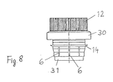
- FIG. 8 shows a top view of the closure cap 12, which is designed as a screw cap, with a guarantee tape 30.
- three ventilation openings 6 can be seen, which are designed as narrow slots with a width of 2.5 mm.
- this embodiment additionally shows an annular separation lip 31 in the area under the air inlet openings 6, which is also shown in the other FIGS. 9 and 10 shown in the following other embodiments.
- This edge or this annular separating lip 31 ensures that the outflowing filling material is not disturbed by the inflowing air.
- the separation lip 31 guides the inflowing air better in the desired direction laterally away from the outflowing filling material.
- FIG. 9 Another embodiment of a closure without bellows is shown in section in FIG. 9, again with the annular separating lip 31, the air inlet openings 6, the ventilation duct 4 and the inner cylinder jacket 8.
- the thread 39 is immediately formed on the outer cylinder jacket, for example for screwing on a screw cap , and below are the annular flanges and recesses of the insert 11 ', which here represents practically the entire plastic ring.
- This closure according to FIG. 9 also allows the ventilation system to be transferred to the tinplate containers.
- FIG. 10 shows a plastic can 1 with a screwed-on closure cap 12, on the left of the dash-dotted center line in section and on the right in plan view.
- This embodiment is not an impact closure, but the closure shown here is screwed onto the container neck 32 as a unit.
- the insert 11 was screwed into the outer screw cap (sealing cover 12) via the thread 40.
- This unit is then screwed over the conical surface (at the air inlet openings 6) with good centering on the external thread of the container neck 32.
- the insert 11 shown in Figure 10 is designed so that it practically takes over the function of a screw cap, because it is simply screwed on in the manner described above and then seals in a double manner, namely on the narrow annular surface at the top of the container neck 32 and also measured on a perpendicular, namely the inner ring surface at a height of about 2 mm from above from the end face.
- a sealing pressure is generated on the end face on the container neck 32 by the screw.
Landscapes
- Engineering & Computer Science (AREA)
- Mechanical Engineering (AREA)
- Closures For Containers (AREA)
Claims (12)
- Fermeture en matière plastique, à aération intégrée, pour récipients en métal ou en matière plastique, comportant uno bague en matière Plastique (11) pouvant être fixée contre l'ouverture (18) du récipient, un bec verseur (2) et au moins un canal d'aération (4), lequel est disposé au moins partiellement dans la zone du bec verseur et s'étend au moins partiellement sur une partie de la longueur du bec verseur (2), le canal d'aération (4) ou ses parois (8, 9) étant reliés d'une manière monobloc et solidaire au bec verseur (2), le canal d'aération (4) étant annulaire, et les parois qui le limitent formant un cylindre intérieur (8) et un cylindre extérieur (9), qui sont reliés l'un à l'autre avec formation d'un double tube au niveau de l'extrémité inférieure, dirigée vers l'intérieur du récipient, des orifices d'aération étant disposés dans la zone inférieure du double tube, caractérisée en ce que le canal d'aération (4) s'étend sur la plus grande partie de la longueur du bec verseur, que les orifices d'aération sont évidés dans le cylindre extérieur (9), que le bec verseur (2) est formé par le cylindre intérieur et que la bague en matière plastique (11) est formée d'une tubulure de communication pouvant être utilisée dans l'ouverture (18) du récipient, et forme un bloc unique et solidaire avec le bec verseur (2).
- Fermeture selon la revendication 1, caractérisée en ce que la section transversale totale des orifices d'aération est nettement plus faible que la section transversale de l'ouverture (5), dirigée vers l'extérieur, du canal d'aération annulaire.
- Fermeture selon la revendication 1, comportant un manchon (7), qui peut se replier dans une ouverture de récipient et peut en être extrait de nouveau, soufflet qui, en son extrémité arrière, eut relié à la bague en matière plastique (11) pouvant être installée dans l'ouverture du récipient, ou directement au bord de l'ouverture du récipient et, en son extrémité avant, d'une manière monobloc et solidaire avec le bec verseur (2), au moins un canal d'aération (4) étant disposé contre la fermeture à soufflet, caractérisée en ce que le canal d'aération (4) est formé indépendamment du soufflet (7).
- Fermeture à soufflet selon la revendication 3, caractérisée en ce que le canal d'aération (4) se termine à une certaine distance du bord supérieur du bec verseur (2).
- Fermeture à soufflet selon la revendication 4, caractérisée en ce qu'un sceau est disposé dans le bec vergeur (2) au-dessus du canal d'aération (4).
- Fermeture à soufflet selon l'une des revendications 3 à 5, caractérisé en ce qu'un sceau recouvrant l'orifice verseur (3) est disposé au niveau du bord supérieur du, bec verseur (2).
- Fermeture à soufflet selon l'une des revendications 4 à 6, caractérisée en ce que l'espace creux formé entre le cylindre intérieur (8) et le cylindre extérieur (9) est subdivisé par des entretoises (13) en plusieurs secteurs formant des canaux d'aération.
- Fermeture à soufflet selon l'une des revendications 3 à 7, caractérisée en ce que la section transversale de l'ouverture (6), dirigée vers l'intérieur du récipient, de chaque canal d'aération (4) est nettement plus petite que la section transversale de l'ouverture (5), dirigée vers l'extérieur, de chaque canal d'aération (4).
- Fermeture à soufflet selon l'une des revendications 3 à a, caractérisée en ce que l'ouverture (6), dirigée vers l'intérieur du récipient, des canaux d'aération (4) est dirigée radialement vers l'extérieur, quand on regarde à partir du milieu de la fermeture.
- Fermeture à soufflet selon l'une des revendications 3 à 9, caractérisée en ce que le bec verseur est, dans sa zone supérieure, pourvu d'un filetage (10) ou d'un bord à enfoncement, destiné à un couvercle de fermeture supplémentaire (12).
- Fermeture à soufflet selon la revendication 10, caractérisé en ce que le couvercle de fermeture (12) est obturé d'une manière étnnche aux liquides vis-à-vis de la fermeture à soufflet ou du récipient.
- Fermeture selon l'une des revendications 1 à 11, caractérisée en ce que le diamètre intérieur, mesuré dans le sens radial, du canal d'aération est d'au moins 2 mm.
Applications Claiming Priority (2)
| Application Number | Priority Date | Filing Date | Title |
|---|---|---|---|
| DE19853542769 DE3542769A1 (de) | 1985-12-04 | 1985-12-04 | Balgverschluss mit integrierter belueftung |
| DE3542769 | 1985-12-04 |
Publications (3)
| Publication Number | Publication Date |
|---|---|
| EP0224863A2 EP0224863A2 (fr) | 1987-06-10 |
| EP0224863A3 EP0224863A3 (en) | 1988-10-05 |
| EP0224863B1 true EP0224863B1 (fr) | 1991-03-20 |
Family
ID=6287524
Family Applications (1)
| Application Number | Title | Priority Date | Filing Date |
|---|---|---|---|
| EP86116414A Expired - Lifetime EP0224863B1 (fr) | 1985-12-04 | 1986-11-26 | Fermeture avec moyens d'aération intégrés |
Country Status (3)
| Country | Link |
|---|---|
| EP (1) | EP0224863B1 (fr) |
| DE (2) | DE3542769A1 (fr) |
| ES (1) | ES2021578B3 (fr) |
Cited By (1)
| Publication number | Priority date | Publication date | Assignee | Title |
|---|---|---|---|---|
| US12252755B2 (en) | 2020-08-19 | 2025-03-18 | Thyssenkrupp Steel Europe Ag | Process for manufacturing a flat steel product having an aluminum-based corrosion-resistant coating, and flat steel product having an aluminum-based corrosion-resistant coating |
Families Citing this family (12)
| Publication number | Priority date | Publication date | Assignee | Title |
|---|---|---|---|---|
| DE3730225A1 (de) * | 1987-09-09 | 1989-03-23 | Berg Jacob Gmbh Co Kg | Kunststoffverschluss fuer einen kunststoffbehaelter |
| GB8722511D0 (en) * | 1987-09-24 | 1987-10-28 | British Petroleum Co Plc | Container for liquids |
| GB8727678D0 (en) * | 1987-11-26 | 1987-12-31 | Goodall D T | Pouring device |
| FR2623778A1 (fr) * | 1987-11-27 | 1989-06-02 | Remy Ets Pierre | Dispositif verseur pour conteneur |
| IT1220581B (it) * | 1988-06-09 | 1990-06-15 | Invat Srl | Tappo per contenitori formato da due elementi incastrati tra loro con alta garanzia contro le manomissioni |
| FR2642046B1 (fr) * | 1989-01-23 | 1991-04-05 | Astra Plastique | Tube verseur escamotable a orientation multidirectionnelle |
| EP0417453A1 (fr) * | 1989-09-11 | 1991-03-20 | Invat S.R.L. | Capuchon extensible pour bouteille ou bidon avec système anti-vol |
| DE3940741A1 (de) * | 1989-12-09 | 1991-06-13 | Berg Jacob Gmbh Co Kg | Ausgiessverschluss mit belueftung |
| DE19807768A1 (de) | 1998-02-24 | 1999-08-26 | Bericap Gmbh & Co | Kunststoffdeckel mit Kunststoffverschluß |
| ES2350780B1 (es) * | 2008-12-10 | 2011-11-18 | Capsulas Torrent, S.A. | Tapon vertedor con canula retraible |
| DE102010009211A1 (de) * | 2010-02-25 | 2011-08-25 | Tbg Technische Beteiligungsgesellschaft Ag | Kanister |
| CN111071618B (zh) * | 2019-12-26 | 2024-08-23 | 李红彪 | 一种可辅助倒取的盖组件 |
Family Cites Families (10)
| Publication number | Priority date | Publication date | Assignee | Title |
|---|---|---|---|---|
| US2040545A (en) * | 1934-09-24 | 1936-05-12 | Byers Edwin Harold | Dispenser cap for containers |
| US2750063A (en) * | 1955-07-14 | 1956-06-12 | Opsitnik William | Non-drip insert for bottles |
| US2898014A (en) * | 1956-08-01 | 1959-08-04 | John E Borah | Combination extensible and foldable vent and spout for containers |
| US3075676A (en) * | 1959-07-31 | 1963-01-29 | South Bend Modern Molding Inc | Container spout |
| DE6802086U (de) * | 1968-10-10 | 1969-04-10 | Theo Schiller | Ausgiessvorrichtung fuer fluessigkeitsbehaelter |
| GB1349535A (en) * | 1971-05-17 | 1974-04-03 | Rieke Corp | Assembly of a container and a closure |
| US4295583A (en) * | 1979-08-09 | 1981-10-20 | Rieke Corporation | Closure cap vent |
| DE3328319A1 (de) * | 1983-08-05 | 1985-02-14 | Wolfram Dr. 7140 Ludwigsburg Schiemann | Auslaufrohr |
| DE3328953A1 (de) * | 1983-08-11 | 1985-02-21 | Jacob Berg Kg, 6501 Budenheim | Behaelterverschluss zum be- oder entlueften eines behaelters |
| DE3342673A1 (de) * | 1983-11-25 | 1985-06-05 | Jacob Berg Kg, 6501 Budenheim | Behaelterverschluss fuer einen behaelter mit einem behaelterhals |
-
1985
- 1985-12-04 DE DE19853542769 patent/DE3542769A1/de not_active Ceased
-
1986
- 1986-11-26 ES ES86116414T patent/ES2021578B3/es not_active Expired - Lifetime
- 1986-11-26 DE DE8686116414T patent/DE3678256D1/de not_active Expired - Lifetime
- 1986-11-26 EP EP86116414A patent/EP0224863B1/fr not_active Expired - Lifetime
Cited By (1)
| Publication number | Priority date | Publication date | Assignee | Title |
|---|---|---|---|---|
| US12252755B2 (en) | 2020-08-19 | 2025-03-18 | Thyssenkrupp Steel Europe Ag | Process for manufacturing a flat steel product having an aluminum-based corrosion-resistant coating, and flat steel product having an aluminum-based corrosion-resistant coating |
Also Published As
| Publication number | Publication date |
|---|---|
| EP0224863A2 (fr) | 1987-06-10 |
| DE3678256D1 (de) | 1991-04-25 |
| ES2021578B3 (es) | 1991-11-16 |
| DE3542769A1 (de) | 1987-06-11 |
| EP0224863A3 (en) | 1988-10-05 |
Similar Documents
| Publication | Publication Date | Title |
|---|---|---|
| DE10202907B4 (de) | Hermetisch verschlossener Behälter mit verbessertem Verschluss | |
| EP3164338B1 (fr) | Bouchon verseur pour le manchon d'un jerrican ou d'un récipient quelconque pour le versement contrôlé vers plusieurs côtés | |
| DE69405393T2 (de) | Selbstschliessende anordnung | |
| DE69500972T2 (de) | Verschlusskappe für einen mit einem einzigen Befestigungsflansch versehenen Behälter | |
| DE69908354T2 (de) | Verschluss mit einer doppelscharnieranordnung | |
| EP0256534B1 (fr) | Cartouche filtrante avec des éléments de guidage du courant | |
| DE10205344B4 (de) | Hermetisch verschlossener Behälter mit durchstechbarem Zugangseinlass | |
| CH652371A5 (de) | Tauchrohr. | |
| DE69915285T2 (de) | Verschluss mit perforiermitteln und ausgiesseinheit | |
| DE1800440A1 (de) | Behaelter | |
| DE1911098A1 (de) | Tube | |
| DE20115489U1 (de) | Abgabeverschluß für fließfähiges Gut enthaltende Behälter | |
| DE69909826T2 (de) | Behälter | |
| DE69402026T3 (de) | Kunststoffschraubdeckel zur Abgabe von Flüssigkeiten | |
| DE69310896T2 (de) | Behälter mit einem Deckel zum verschliessen eines Endes von insbesondere einem im wesentlichen zylindrischen Rohrteil | |
| DE2644786C3 (de) | Ausgabedüse, insbesondere für flüssige und halbflüssige Substanzen | |
| EP0224863A2 (fr) | Fermeture avec moyens d'aération intégrés | |
| DE2209739C3 (de) | AusgieBstutzen | |
| DE9303734U1 (de) | Trinkverschluß für eine Trinkflasche | |
| DE69007131T2 (de) | Spender für creme- oder pastenartige Produkte mit zentraler, durch Drehung zu öffnender Verschlussöffnung. | |
| DE4219571C2 (de) | Vorrichtung zur Entnahme einer Flüssigkeit aus einem Behälter, insbesondere aus einer 10- bzw. 5-Liter Faßdose für Bier | |
| DE69100602T2 (de) | Abgabevorrichtung für flüssige oder pastöse Produkte, insbesondere für kosmetische Produkte. | |
| EP3558840B1 (fr) | Obturateur de versement | |
| DE69104202T2 (de) | Einwegbehälter für einzelportionen. | |
| DE10124835A1 (de) | Verschluss mit integrierter Belüftung |
Legal Events
| Date | Code | Title | Description |
|---|---|---|---|
| PUAI | Public reference made under article 153(3) epc to a published international application that has entered the european phase |
Free format text: ORIGINAL CODE: 0009012 |
|
| AK | Designated contracting states |
Kind code of ref document: A2 Designated state(s): DE ES FR GB IT NL SE |
|
| PUAL | Search report despatched |
Free format text: ORIGINAL CODE: 0009013 |
|
| AK | Designated contracting states |
Kind code of ref document: A3 Designated state(s): DE ES FR GB IT NL SE |
|
| 17P | Request for examination filed |
Effective date: 19881028 |
|
| 17Q | First examination report despatched |
Effective date: 19890203 |
|
| ITF | It: translation for a ep patent filed | ||
| GRAA | (expected) grant |
Free format text: ORIGINAL CODE: 0009210 |
|
| AK | Designated contracting states |
Kind code of ref document: B1 Designated state(s): DE ES FR GB IT NL SE |
|
| GBT | Gb: translation of ep patent filed (gb section 77(6)(a)/1977) | ||
| ET | Fr: translation filed | ||
| REF | Corresponds to: |
Ref document number: 3678256 Country of ref document: DE Date of ref document: 19910425 |
|
| PLBI | Opposition filed |
Free format text: ORIGINAL CODE: 0009260 |
|
| PLAB | Opposition data, opponent's data or that of the opponent's representative modified |
Free format text: ORIGINAL CODE: 0009299OPPO |
|
| 26 | Opposition filed |
Opponent name: VEREINIGTE ALUMINIUM WERKE AG Effective date: 19911219 |
|
| R26 | Opposition filed (corrected) |
Opponent name: N.V. GEVAERT PLASTIC PRODUCTS S.A. Effective date: 19911219 |
|
| NLR1 | Nl: opposition has been filed with the epo |
Opponent name: N.V. GEVAERT PLASTIC PRODUCTS S.A. |
|
| PGFP | Annual fee paid to national office [announced via postgrant information from national office to epo] |
Ref country code: GB Payment date: 19931014 Year of fee payment: 8 |
|
| PGFP | Annual fee paid to national office [announced via postgrant information from national office to epo] |
Ref country code: FR Payment date: 19931018 Year of fee payment: 8 |
|
| PGFP | Annual fee paid to national office [announced via postgrant information from national office to epo] |
Ref country code: SE Payment date: 19931029 Year of fee payment: 8 |
|
| PGFP | Annual fee paid to national office [announced via postgrant information from national office to epo] |
Ref country code: ES Payment date: 19931110 Year of fee payment: 8 |
|
| PGFP | Annual fee paid to national office [announced via postgrant information from national office to epo] |
Ref country code: NL Payment date: 19931130 Year of fee payment: 8 |
|
| PGFP | Annual fee paid to national office [announced via postgrant information from national office to epo] |
Ref country code: DE Payment date: 19931223 Year of fee payment: 8 |
|
| RDAC | Information related to revocation of patent modified |
Free format text: ORIGINAL CODE: 0009299REVO |
|
| RDAG | Patent revoked |
Free format text: ORIGINAL CODE: 0009271 |
|
| STAA | Information on the status of an ep patent application or granted ep patent |
Free format text: STATUS: PATENT REVOKED |
|
| 27W | Patent revoked |
Effective date: 19940325 |
|
| GBPR | Gb: patent revoked under art. 102 of the ep convention designating the uk as contracting state |
Free format text: 940325 |
|
| NLR2 | Nl: decision of opposition | ||
| R27W | Patent revoked (corrected) |
Effective date: 19940325 |
|
| EUG | Se: european patent has lapsed |
Ref document number: 86116414.3 Effective date: 19940810 |