EP0224892A1 - Verfahren und Vorrichtung zum Herstellen einer kontinuierlichen Stoffbahn - Google Patents
Verfahren und Vorrichtung zum Herstellen einer kontinuierlichen Stoffbahn Download PDFInfo
- Publication number
- EP0224892A1 EP0224892A1 EP86116607A EP86116607A EP0224892A1 EP 0224892 A1 EP0224892 A1 EP 0224892A1 EP 86116607 A EP86116607 A EP 86116607A EP 86116607 A EP86116607 A EP 86116607A EP 0224892 A1 EP0224892 A1 EP 0224892A1
- Authority
- EP
- European Patent Office
- Prior art keywords
- outlet
- convex surface
- fibres
- reject
- accept
- Prior art date
- Legal status (The legal status is an assumption and is not a legal conclusion. Google has not performed a legal analysis and makes no representation as to the accuracy of the status listed.)
- Granted
Links
- 238000000034 method Methods 0.000 title claims description 16
- 238000009826 distribution Methods 0.000 claims abstract description 26
- 239000000463 material Substances 0.000 claims abstract description 25
- 230000007704 transition Effects 0.000 claims abstract description 24
- 239000011362 coarse particle Substances 0.000 claims abstract description 9
- 239000012159 carrier gas Substances 0.000 claims abstract description 8
- 230000032258 transport Effects 0.000 claims abstract description 8
- 238000004519 manufacturing process Methods 0.000 claims abstract description 4
- 239000000835 fiber Substances 0.000 claims description 29
- 239000000725 suspension Substances 0.000 claims description 28
- 239000007789 gas Substances 0.000 claims description 13
- 238000005192 partition Methods 0.000 claims description 6
- 238000000926 separation method Methods 0.000 claims description 5
- 230000007423 decrease Effects 0.000 claims description 4
- 230000000694 effects Effects 0.000 claims description 4
- 230000002093 peripheral effect Effects 0.000 claims description 3
- 238000011144 upstream manufacturing Methods 0.000 claims description 3
- 230000001419 dependent effect Effects 0.000 claims description 2
- 238000000605 extraction Methods 0.000 abstract 1
- 239000003570 air Substances 0.000 description 25
- 230000008859 change Effects 0.000 description 6
- 238000009740 moulding (composite fabrication) Methods 0.000 description 6
- 238000012216 screening Methods 0.000 description 4
- 239000012080 ambient air Substances 0.000 description 3
- 239000002245 particle Substances 0.000 description 3
- 238000009827 uniform distribution Methods 0.000 description 3
- 229920003043 Cellulose fiber Polymers 0.000 description 2
- 229920002522 Wood fibre Polymers 0.000 description 2
- 238000005054 agglomeration Methods 0.000 description 2
- 230000002776 aggregation Effects 0.000 description 2
- 230000008901 benefit Effects 0.000 description 2
- 239000011230 binding agent Substances 0.000 description 2
- 230000003247 decreasing effect Effects 0.000 description 2
- 239000007787 solid Substances 0.000 description 2
- OKTJSMMVPCPJKN-UHFFFAOYSA-N Carbon Chemical compound [C] OKTJSMMVPCPJKN-UHFFFAOYSA-N 0.000 description 1
- 230000004888 barrier function Effects 0.000 description 1
- 229910052799 carbon Inorganic materials 0.000 description 1
- 239000004568 cement Substances 0.000 description 1
- 238000000576 coating method Methods 0.000 description 1
- 238000000151 deposition Methods 0.000 description 1
- 230000002349 favourable effect Effects 0.000 description 1
- 239000011491 glass wool Substances 0.000 description 1
- 229910052500 inorganic mineral Inorganic materials 0.000 description 1
- 239000000543 intermediate Substances 0.000 description 1
- 230000005012 migration Effects 0.000 description 1
- 238000013508 migration Methods 0.000 description 1
- 238000003801 milling Methods 0.000 description 1
- 239000011707 mineral Substances 0.000 description 1
- 239000011490 mineral wool Substances 0.000 description 1
- 238000012986 modification Methods 0.000 description 1
- 230000004048 modification Effects 0.000 description 1
- 230000010355 oscillation Effects 0.000 description 1
- 230000003534 oscillatory effect Effects 0.000 description 1
- 230000008569 process Effects 0.000 description 1
- 230000000541 pulsatile effect Effects 0.000 description 1
- 230000010349 pulsation Effects 0.000 description 1
- 239000012265 solid product Substances 0.000 description 1
- 239000007921 spray Substances 0.000 description 1
- 230000002311 subsequent effect Effects 0.000 description 1
- 230000008093 supporting effect Effects 0.000 description 1
- 229920002994 synthetic fiber Polymers 0.000 description 1
- 239000004753 textile Substances 0.000 description 1
- 238000012546 transfer Methods 0.000 description 1
- 239000002699 waste material Substances 0.000 description 1
Images


Classifications
-
- B—PERFORMING OPERATIONS; TRANSPORTING
- B27—WORKING OR PRESERVING WOOD OR SIMILAR MATERIAL; NAILING OR STAPLING MACHINES IN GENERAL
- B27N—MANUFACTURE BY DRY PROCESSES OF ARTICLES, WITH OR WITHOUT ORGANIC BINDING AGENTS, MADE FROM PARTICLES OR FIBRES CONSISTING OF WOOD OR OTHER LIGNOCELLULOSIC OR LIKE ORGANIC MATERIAL
- B27N3/00—Manufacture of substantially flat articles, e.g. boards, from particles or fibres
- B27N3/08—Moulding or pressing
- B27N3/10—Moulding of mats
- B27N3/14—Distributing or orienting the particles or fibres
-
- B—PERFORMING OPERATIONS; TRANSPORTING
- B07—SEPARATING SOLIDS FROM SOLIDS; SORTING
- B07B—SEPARATING SOLIDS FROM SOLIDS BY SIEVING, SCREENING, SIFTING OR BY USING GAS CURRENTS; SEPARATING BY OTHER DRY METHODS APPLICABLE TO BULK MATERIAL, e.g. LOOSE ARTICLES FIT TO BE HANDLED LIKE BULK MATERIAL
- B07B7/00—Selective separation of solid materials carried by, or dispersed in, gas currents
- B07B7/08—Selective separation of solid materials carried by, or dispersed in, gas currents using centrifugal force
- B07B7/086—Selective separation of solid materials carried by, or dispersed in, gas currents using centrifugal force generated by the winding course of the gas stream
-
- B—PERFORMING OPERATIONS; TRANSPORTING
- B07—SEPARATING SOLIDS FROM SOLIDS; SORTING
- B07B—SEPARATING SOLIDS FROM SOLIDS BY SIEVING, SCREENING, SIFTING OR BY USING GAS CURRENTS; SEPARATING BY OTHER DRY METHODS APPLICABLE TO BULK MATERIAL, e.g. LOOSE ARTICLES FIT TO BE HANDLED LIKE BULK MATERIAL
- B07B9/00—Combinations of apparatus for screening or sifting or for separating solids from solids using gas currents; General arrangement of plant, e.g. flow sheets
-
- D—TEXTILES; PAPER
- D21—PAPER-MAKING; PRODUCTION OF CELLULOSE
- D21H—PULP COMPOSITIONS; PREPARATION THEREOF NOT COVERED BY SUBCLASSES D21C OR D21D; IMPREGNATING OR COATING OF PAPER; TREATMENT OF FINISHED PAPER NOT COVERED BY CLASS B31 OR SUBCLASS D21G; PAPER NOT OTHERWISE PROVIDED FOR
- D21H27/00—Special paper not otherwise provided for, e.g. made by multi-step processes
Definitions
- the present invention relates to a method for producing a material web of the kind apparent from the pre-characterizing clause of Claim 1.
- the invention also relates to an arrangement of apparatus for producing the web in accordance with the method.
- a web can be produced by depositing a gaseous suspension of fibres or other particles onto a continuous web-forming belt.
- US-A-3 071 822 describes a method in which the fibres are deposited through the intermediary of an oscillating nozzle, which is caused to traverse backwards and forwards across the belt with the aid of mechanical devices intended herefor.
- This arrangement is encumbered with a number of drawbacks.
- the oscillating frequency of the nozzle is restricted to about 1-2 oscillations per second. It is difficult to achieve suitable oscillatory movement that will provide uniform distribution of material over the continuously moving web-forming belt.
- SE-B-7510795-3 describes another arrangement which comprises a distribution chamber and a nozzle assembly which discharges into the chamber.
- the nozzle assembly has an elongated aperture which extends in the longitudinal direction of the forming belt.
- a supply means having openings or jets which face the incoming stream of fibres and through which there is delivered a pulsatile flow of steering gas of variable pulsation.
- the incoming stream of fibres is subjected to powerful impulses from the steering jets, which disperse the fibres, or material, throughout the distribution chamber in the form of fibre curtains, which are deposited onto the continuously moving belt or like carrier surface.
- the frequency at which the steering jets change the direction of the fibre stream is higher than in the case of the mechanical arrangement, e.g. from 5 to 15 times per second.
- SE-B-7703460-1 is a patent of addition to the abovementioned patent and describes a particularly advantageous arrangement for achieving uniform distribution of the fibres, or material, in the nozzle. This is effected by causing the flow of material to pass a zig-zag transition zone located upstream of the nozzle, as seen in the flow direction, and diverging towards the nozzle. The transition zone increases in area in a direction towards the nozzle, therewith resulting in a velocity decrease of the incoming flow of material. Passage of the material flow through the zig-zag transition zone results in uniform distribution of the material in the longitudinal direction of the nozzle.
- Another object of this invention is to provide a method for producing a material web of low grammage at high belt speeds with uniform material distribution to achieve uniform web thickness over the width of the belt in the absence of pronounced material agglomerations, and to improve generally the technique of producing webs of material, through the deposit of material in gaseous suspension.
- Another object of the invention is to provide an arrangement of apparatus for carrying out the method.
- Figure 1 there is illustrated an arrangement of apparatus for producing a material web, comprising a preparatory station 10 (not described in detail) for producing or dispensing fibres, a transport conduit 12 for transporting fibres suspended in a gaseous medium, a blower 14 for effecting said transport; a symbolically illustrated pre-separator 16 for separating coarse particles, distribution and delivery apparatus 18, and a web forming machine 20.
- the distribution and delivery apparatus 18 incorporates a separator 22 which separates fibre-bundles and coarse particles from the suspension immediately prior to the delivery thereof.
- the machine 20 of which only those components that are active in the process have been shown, comprises an endless, gas-permeable belt or wire 24, two terminal rollers 26, at least one bottom roller 28, screen means in the form of transverse rods or a perforated plate 30 ( Figure 4) supporting the wire, and a suction box 32.
- the wire is arranged for movement in the direction of the arrow 34.
- a web 36 formed on the machine 20 is transferred therefrom to other machines, not shown, for continued treatment.
- the machine 20 may incorporate more than one distribution and delivery apparatus 18 with associated suction box. This will enable a thicker web to be produced, or a web compris ing various layers of material.
- the distribution and delivery apparatus 18 incorporates a zig-zag or sinusoidal transition part 38 having an outlet aperture 40 which transverses the endless belt or wire 24.
- the transition part 28 comprises a series of interconnected sections a - g which together form the aforesaid zig-zag configuration and the interconnecting curves of which are substantially parallel to the outlet aperture 40.
- the sections increase in width from the inlet end of the tranition part to the outlet and thereof, while decreasing in thickness at the same time, such that the total throughflow area presented decreases in a direction towards the outlet aperture. This decreasing area results in an increase in the velocity of the fibre suspension as it passes through the transition part.
- the section b has provided therein a plurality of ports 42 through which air is introduced into the suspension for the purpose of thinning the same, said inlet ports being provided with air intake shutters 44 and being connected to a common air conduit 46.
- Any irregularities in fibre dispension in the incoming fibre suspension can be compensated for, by appropriate adjustment to the settings of the air intake shutters. These irregularities may result from the particular geometry of the transport conduit 12 and persist with time.
- the aformentioned coarse particle separator 22 is located in the vicinity of the outlet aperture 40, and has an accept outlet 48 for fibres 50 which pass to a distribution chamber 52 located above the wire 24 and its suction box 32, and a reject outlet 54 for coarse fibres and fibre agglomerates 56, 57 connected to a collecting chest 58.
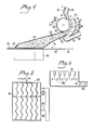
- the separator includes a curved, convex surface 60, which may comprise the peripheral surface of a drum 62 ( Figures 1-4) arranged for rotation in the flow direction. According to an alternative embodiment in Figure 7, the convex surface may comprise a stationary single-surface or two curved surfaces ( Figure 8).
- one defining wall 38′ of the transition section 38 merges with the aperture 40 adjacent the convex surface 60.
- the other defining wall 38 ⁇ of the section has arranged therein an air inlet 64 for recycled air and ambient air.
- the separator operates in the following manner.
- the incoming fibre suspension is deflected along the curved surface 60, as a result of the so-called Coanda-effect.
- the fibre suspension follows an inner path 66 and leaves the separator through the accept outlet 48.
- Air moves from the air inlet 64 to the reject outlet 54, in an outer path 68 located externally of said inner path.
- Coarse particles 56 and fibre agglomerations have greater kinetic energy, due to their greater mass, and are therefore influenced to a lesser extent by the carrier gas of the fibre suspension. Consequently this material of greater mass will move in a straighter path, through a boundary layer 70 to the outer path, and out through the reject outlet 54.
- the extension of the outer and inner paths, and therewith the separation limit of the separator can be adjusted by changing the setting of an adjustable tongue 72 located between the accept outlet 48 and the reject outlet 54.
- the reject outlet 54 leads to a collecting chest 58 for separated particles and agglomerates.
- the chest tapers down towards an outlet conduit 74.
- the top angle is suitably about 60° or less.
- Two or more outlets are provided in the case of widths greater than about one meter.
- the outlet conduit communicates with a separator 76 for solid goods 78, and a fan blower, or the like 80.
- the separated solids 78 may be returned to the preparatory station 10, or used in some other way, or may be dumped as waste, in accordance with prevailing circumstances.
- the fibres from the accept outlet 48 enter the distribution chamber 52 and disperse over the endless, perforated belt 24,the carriergas being drawn by suction through said belt and into a suction box 32.
- the suction box 32 is divided in the direction of its longitudinal axis by zig-zag shaped partition walls 82.
- the zig-zag shaped walls provide a diffuse boundary zone between the different suction boxes, therewith avoiding the occurence of zones of lower suction effect, such zones being liable to result in an uneven web.
- the suction box may also be divided in the movement direction 34 of the web 24, with the aid of one or more transverse walls 84.
- the suction box 32 and suction outlet conduit 86 are each fitted with a respective valve means 88 and 90. Since the amount of fibres deposited above a suction-box section is dependent at least in part on the amount of gas drawn through the belt or wire, the profile of the web can be controlled to a certain extent with the aid of these valves. The valves can be adjusted manually or automatically to appropriate settings, subsequent to determining the thickness or grammage of the resultant web in a known manner.
- the separation boundary of the separator 22 is contingent, inter alia, on the velocity of the gas in the various openings and apertures; i.e. the outlet aperture 40, the air inlet, 64, the accept outlet 48 and the reject outlet 54.
- the settings of these air velocities is therefore an important operating parameter of the separator 22.
- Another important operating parameter is the setting of the adjustable tongue 72.
- the gas increases in velocity as it passes through the transition part 38.
- gas velocities are:
- Transport conduit 20m/sec. Inlet end of the delivery apparatus 18: 25m/sec. Outlet aperture 40: 40m/sec
- the curved, convex surface 60 is preferably caused to move in the direction of gas flow at the same speed as the gas and the fibres suspended therein. Both lower and higher speeds are conceivable, however.
- the movable surface 60 of the illustrated embodiment comprises the peripheral surface of a drum. It may, however, alternatively have the form of a belt that is arranged to move around guide surfaces and guide rollers in a closed loop. Obviously, the surface 60 may have many different forms, although a drum is the embodiment preferred.
- the dynamic forces have dominence over gravitational forces, when the separator 22 is in operation. Consequently, the zig-zag transition part 38 and the separator 22 and its outlet 48, 54 can be orientated in any desired position relative to the vertical. This also applies to the distribution chamber 52.
- the angle ⁇ between the perforated belt 24 and the median line of the delivered fibre flow can be any desired angle. Thus, the angle can be much larger than the illustrated angle of about 20°, and may, for example, be 60° or even close to 90°, or greater than 90°.
- the air inlet 64 follows the zig-zag or sinusoidal transition part 38 along several transition curves. This is not a necessary requirement, however, since the air inlet 64 may also have an inlet opening which is located in the immediate proximity of the outlet aperture 40, and/or may be straight.
- the flow of fibre suspension is caused to change direction at the region of the curved, convex surface 60 through an angle of 90°, so as to effectively separate coarse fibres or particles from the flow.
- Directional changes smaller or greater than 90° are conceivable, however, depending on other operational variables, such as, for instance, differing gas velocities and the sizes of the various openings and apertures.
- the smallest change in direction in which coarse particles can be separated effectively under favourable conditions is thought to be 30°, however.
- the largest directional change is limited upwardly by the angle at which the air stream no longer adheres to said surface. This angle can be expected to be larger when the surface moves in the direction of the air stream.
- the convex surface may also comprise two separate convex surfaces.
- Figure 8 illustrates an arrangement comprising a first convex surface 92 with a directional change of about 60° and a second deflection surface 94 with a directional change of about 30°.
- the separator illustrated in Figure 8 can also be used as a pre-separator, referenced 16, as explained in more detail hereinafter.
- Figure 8 also illustrates a preferred velocity profile or configuration 96 for the incoming fibre suspension. According to this velocity profile, the speed of the incoming suspension is greatest nearest the curved surface.
- the illustrated velocity profile is obtained by incorporating upstream of the curved surface a further curve or bend 98 curving in a direction opposite to the deflecting direction of the curved surface 60. This further curve or bend 98 terminates the zig-zag shaped transition part of said arrangement.
- Figure 4 illustrates in broken lines a boundary layer 70 which extends from the partition wall between the outlet aperture 40 and the air intake 64.
- the outgoing velocities can also be selected so that boundary layer 70′ extends into the air inlet 64 and partitions off a part of this air to the accept oulet 48.
- This separated airflow acts as a barrier, to prevent fibres of accept quality from passing across the boundary layer to the reject outlet. This migration of accept fibres can otherwise readily occur in the case of such fibres which are present in the outlet aperture i.e. initially in the near vicintiy of the air inlet 64 and the boundary layer 70.
- the convex surface 60 is given a radius of curvature in the order of magnitude of 15 cm, when the incoming velocity is 40m/sec.
- Figure 7 illustrates another embodiment of a separator, here referenced 22a, which incorporates a stationary curved surface 60a. Details and components of the Figure 7 embodiment that coincide with the embodiment earlier described are identified by the same references suffixed with the letter a .
- FIG 8 A further embodiment of the separator is illustrated in Figure 8, and comprises the two aforementioned convex surfaces 92 and 94.
- This alternative separator, here referenced 22′ incorporates an auxiliary separating or screening device in the form of a screening grid 100, which is intended to screen out lightweight bundles or fibre agglomerates 57.
- the screening grid comprises a transverse beam 102 and rods or fingers 104 extending outwardly therefrom.
- the screen extends from one wall 52′, through a passage 106 located in the opposite wall 52 ⁇ of the inlet of the downstream distribution chamber 52, such as to transfer coarse material to the collecting chest 58.
- the screen 100 also forms a safety device in the event of operational disturbances.
- the separator 22′ has a fibre suspension inlet 40′, an air inlet 64′, an accept outlet 48′, and a reject outlet 54′.
- the reject outlet 54′ is connected to a solid-product separator and a fan.
- the air inlet 64′ is preferivelyably connected to a source for recycled air, although it may alternatively be open to ambient air.
- the separator 22′ of this embodiment may also have any desired position of orientation to the vertical, since the dynamic forces dominate over the gravitational forces.
- a screening grid 100 corresponding to that illustrated in Figures 8 and 9 can also be incorporated in a separator 22 with rotating drum 62 according to Figures 1 and 4.
- a pre-separator 16 may be arranged to advantage upstream of the distribution and delivery apparatus 18 of a web forming plant of the aforesaid kind.
- the function of the pre-separator is to effect primary separation of coarse particles and fibre agglomerates from the incoming fibre suspension.
- the pre-separator 16 may have any desirable form, and may also have the form of the aforedescribed separator incorporating a convex surface and utilizing the Coanda-effect.
- the distribution and delivery apparatus 18 has a maximum width of about 1m.
- a plurality of distribution and delivery apparatus 18 are arranged adjacent one another, with a common distribution chamber 52. This enables the fibres to be dispersed evenly over the whole width of the web.
- the arrangement according to the invention can be used to produce webs from any type of fibre.
- a preferred material is cellulose-fibre and wood-fibre.
- Other conceivable fibres are textile fibres (lump), synthetic fibres, carbon fibres, and mineral fibres (e.g. glass wool and mineral wool).
- One or more of these latter types of fibre can be used to enhance the mechanical strength properties or other properties of a cellulose-fibre or wood- fibre web.
- the fibres used may have a length ranging from a minimum length close to zero, up to about 15-20mm.
- the binders required to cement the material web can be introduced in a subsequent treatment stage, downstream of the machine 20, in a known manner.
- the binder may be mixed with the fibre suspension and dispersed together with the fibres.
- the space defined by the drum 62 and a rearwardly lying housing wall 61 is preferably at most a narrow gap 63. It is particularly essential that the gap is narrow at its inlet end, in order to avoid air or fibres being entrained thereinto, which otherwise may cause operational disturbances. Operationally, a shield, for example in the form of a rubber plate or the like, may be fitted in front of the gap.
- the opposing wall 65 of the convex suface 60 of the separator 22 has approximately the same configuration as the surface 60.
- the fibre suspension has the desired velocity at the outlet aperture 40.
- This velocity may be different to the aforesaid velocity of 30-40m/s.
- the separator is correspondingly adapted, by modifying the radius of the curved surface 60 accordingly. The radius of the surface shall therewith be proportional to the square of the velocity.
- transition part Neither need the transition part have the zig-zag configuration according to SE-B 7703460-1.
- the separator 22 is preceded by at least one curve 98 which is counter-directional to the deflecting direction of the curved surface. Neither is it necessary for the zig-zag configuration or the curve 98 to exhibit sharp corners, as with the illustrated embodiments, but that they may incorporate rounded bends, which may optionally merge immediately one with the other, with no intermediate straight parts.
- a distribution chamber 52 is arranged immediately downstream of the separator 22. It is also possible, however, to arrange a separate distribution or spray device, for example according to US-A 3 071 822 or SE-B 7510795-3, between the separator and the distribution chamber, for distribution of the fibres over the continuously moving belt.
Landscapes
- Life Sciences & Earth Sciences (AREA)
- Engineering & Computer Science (AREA)
- Manufacturing & Machinery (AREA)
- Wood Science & Technology (AREA)
- Forests & Forestry (AREA)
- Nonwoven Fabrics (AREA)
- Preliminary Treatment Of Fibers (AREA)
- Packaging For Recording Disks (AREA)
- Microscoopes, Condenser (AREA)
- Manufacturing Of Electric Cables (AREA)
- Developing Agents For Electrophotography (AREA)
- Crystals, And After-Treatments Of Crystals (AREA)
- Compositions Of Oxide Ceramics (AREA)
- Road Paving Structures (AREA)
- Cigarettes, Filters, And Manufacturing Of Filters (AREA)
- Treatment Of Fiber Materials (AREA)
- Saccharide Compounds (AREA)
- Curing Cements, Concrete, And Artificial Stone (AREA)
- Processing And Handling Of Plastics And Other Materials For Molding In General (AREA)
Priority Applications (1)
| Application Number | Priority Date | Filing Date | Title |
|---|---|---|---|
| AT86116607T ATE46724T1 (de) | 1985-12-04 | 1986-11-28 | Verfahren und vorrichtung zum herstellen einer kontinuierlichen stoffbahn. |
Applications Claiming Priority (2)
| Application Number | Priority Date | Filing Date | Title |
|---|---|---|---|
| SE8505726A SE457729B (sv) | 1985-12-04 | 1985-12-04 | Saett och anordning foer torrformning av en fiberbana |
| SE8505726 | 1985-12-04 |
Publications (2)
| Publication Number | Publication Date |
|---|---|
| EP0224892A1 true EP0224892A1 (de) | 1987-06-10 |
| EP0224892B1 EP0224892B1 (de) | 1989-09-27 |
Family
ID=20362333
Family Applications (1)
| Application Number | Title | Priority Date | Filing Date |
|---|---|---|---|
| EP86116607A Expired EP0224892B1 (de) | 1985-12-04 | 1986-11-28 | Verfahren und Vorrichtung zum Herstellen einer kontinuierlichen Stoffbahn |
Country Status (10)
| Country | Link |
|---|---|
| US (1) | US4712277A (de) |
| EP (1) | EP0224892B1 (de) |
| AT (1) | ATE46724T1 (de) |
| CA (1) | CA1264518A (de) |
| DE (1) | DE3665892D1 (de) |
| DK (1) | DK161343C (de) |
| ES (1) | ES2010658B3 (de) |
| FI (1) | FI84500C (de) |
| NO (1) | NO161389C (de) |
| SE (1) | SE457729B (de) |
Cited By (7)
| Publication number | Priority date | Publication date | Assignee | Title |
|---|---|---|---|---|
| WO1991005109A1 (en) * | 1989-09-28 | 1991-04-18 | Ove Ahlstrand | Apparatus and method for producing a fiber material web |
| FR2700138A1 (fr) * | 1993-01-06 | 1994-07-08 | Weisskopf Charles | Procédé et dispositif pour la production d'articles par compactage de fibres ou granulés à l'aide d'un courant d'air et articles ainsi produits. |
| WO1995000261A1 (en) * | 1993-06-18 | 1995-01-05 | ABB Fläkt AB | Method and device for separating heavy particles from a particulate material |
| EP2191047A4 (de) * | 2007-08-17 | 2011-04-27 | A D Jezzi & Associates Llc | Vorrichtung zur gleichmässigen verteilung von fasern in einem luftstrom |
| WO2011156300A1 (en) * | 2010-06-09 | 2011-12-15 | The Procter & Gamble Company | Apparatus for separating particles and methods for using same |
| WO2018065749A1 (en) * | 2016-10-05 | 2018-04-12 | British American Tobacco (Investments) Limited | Method and equipment for gathering fibres |
| US11794424B2 (en) | 2017-03-24 | 2023-10-24 | British American Tobacco (Investments) Limited | Die, die assembly, equipment and method for forming rods of fibrous material |
Families Citing this family (17)
| Publication number | Priority date | Publication date | Assignee | Title |
|---|---|---|---|---|
| DE3901313A1 (de) * | 1989-01-18 | 1990-07-19 | Hollingsworth Gmbh | Vlieskrempel |
| DE3928280C2 (de) * | 1989-08-26 | 2001-03-22 | Truetzschler Gmbh & Co Kg | Vorrichtung zum Speisen von in Flockenform befindlichem Fasergut, z. B. Baumwolle, Chemiefasern u. dgl., zu einer Karde oder Krempel |
| US5102585A (en) * | 1990-01-09 | 1992-04-07 | Kimberly-Clark Corporation | Method for intermittently depositing particulate material in a substrate |
| US5028224A (en) * | 1990-01-09 | 1991-07-02 | Kimberly-Clark Corporation | Apparatus for intermittently depositing particulate material in a substrate |
| US4991264A (en) * | 1990-01-16 | 1991-02-12 | International Paper Company | Apparatus and method for use in-line with a card to enhance tensile strength in nonwoven materials |
| DE4036014C2 (de) * | 1990-11-13 | 2001-07-05 | Truetzschler Gmbh & Co Kg | Vorrichtung zum Herstellen eines Faservlieses, z.B. aus Chemiefasern, Baumwolle, Zellwolle u. dgl. |
| DE4239577C2 (de) * | 1991-12-05 | 1996-06-05 | Fehrer Ernst | Vorrichtung zum Herstellen eines Faservlieses |
| US5539958A (en) * | 1995-09-13 | 1996-07-30 | Groupe Laperri ere et Verreault | Aerodynamic forming hood and method of operation |
| SE511698C2 (sv) * | 1998-03-20 | 1999-11-08 | Sunds Defibrator Ind Ab | Anordning för separering av partiklar |
| WO2000004232A1 (en) | 1998-07-14 | 2000-01-27 | M & J Fibretech A/S | Nits separator |
| US20050269850A1 (en) * | 1999-11-24 | 2005-12-08 | Total Innovative Manufacturing, Llc | Removable seat cushion |
| DE10022499A1 (de) * | 2000-05-09 | 2001-11-15 | Winkler & Duennebier Ag | Vorrichtung zum Bereitstellen eines von Flockenverklumpungen im wesentlichen freien Flocken-Luft-Gemisches sowie Verfahren zum Auflösen von Flockenverklumpungen |
| EP1666386B1 (de) * | 2004-12-03 | 2009-01-14 | Bobst S.A. | Vorrichtung und Verfahren zum Ausrichten von flachen Gegenständen |
| JP5629525B2 (ja) * | 2010-08-06 | 2014-11-19 | 花王株式会社 | 不織布の嵩増加装置 |
| AT515297B1 (de) * | 2014-01-22 | 2015-08-15 | Wintersteiger Ag | Vorrichtung zum Abscheiden eines körnigen Guts aus einem Förderluftstrom |
| US11857052B2 (en) | 2020-04-01 | 2024-01-02 | Omachron Intellectual Property Inc. | Water separator for a hair dryer |
| DE102023129657A1 (de) * | 2023-10-27 | 2025-04-30 | Voith Patent Gmbh | Verfahren und Maschine zur Herstellung einer trockengelegten Faserstoffbahn |
Citations (3)
| Publication number | Priority date | Publication date | Assignee | Title |
|---|---|---|---|---|
| DE1802161B2 (de) * | 1967-10-10 | 1974-08-01 | Domtar Ltd., Montreal, Quebec (Kanada) | Vorrichtung zum Herstellen von Matten, Vliesen od.dgl. aus faserförmigen Teilchen |
| EP0040693A1 (de) * | 1980-04-25 | 1981-12-02 | Bayer Ag | Verfahren und Vorrichtung zur Herstellung von Fasermatten |
| SU1110845A1 (ru) * | 1983-04-26 | 1984-08-30 | Всесоюзное научно-производственное объединение целлюлозно-бумажной промышленности | Устройство дл сухого формовани бумаги из потока аэровзвеси волокнистого материала |
Family Cites Families (4)
| Publication number | Priority date | Publication date | Assignee | Title |
|---|---|---|---|---|
| US2810163A (en) * | 1956-09-05 | 1957-10-22 | George J Kyame | Textile fiber cleaning machine |
| US3071822A (en) * | 1959-03-03 | 1963-01-08 | Bowater Board Company | Method and apparatus for forming a mat |
| SE397943B (sv) * | 1975-09-26 | 1977-11-28 | Svenska Flaektfabriken Ab | Sett och anordning for att forma en materialbana genom avsettning av i en fordelningskammare instrommande i gasformigt medium fordelad strom av partiklar, exempelvis fibrer, pa en i fordelningskammaren anordnad ... |
| SE447807B (sv) * | 1985-05-08 | 1986-12-15 | Kmw Ab | Sett och apparat for framstellning av en materialbana |
-
1985
- 1985-12-04 SE SE8505726A patent/SE457729B/sv not_active IP Right Cessation
-
1986
- 1986-11-21 NO NO864661A patent/NO161389C/no not_active IP Right Cessation
- 1986-11-26 CA CA000523823A patent/CA1264518A/en not_active Expired - Fee Related
- 1986-11-28 FI FI864861A patent/FI84500C/fi not_active IP Right Cessation
- 1986-11-28 EP EP86116607A patent/EP0224892B1/de not_active Expired
- 1986-11-28 ES ES86116607T patent/ES2010658B3/es not_active Expired
- 1986-11-28 AT AT86116607T patent/ATE46724T1/de active
- 1986-11-28 DE DE8686116607T patent/DE3665892D1/de not_active Expired
- 1986-12-01 DK DK576786A patent/DK161343C/da not_active IP Right Cessation
- 1986-12-03 US US06/937,562 patent/US4712277A/en not_active Expired - Lifetime
Patent Citations (3)
| Publication number | Priority date | Publication date | Assignee | Title |
|---|---|---|---|---|
| DE1802161B2 (de) * | 1967-10-10 | 1974-08-01 | Domtar Ltd., Montreal, Quebec (Kanada) | Vorrichtung zum Herstellen von Matten, Vliesen od.dgl. aus faserförmigen Teilchen |
| EP0040693A1 (de) * | 1980-04-25 | 1981-12-02 | Bayer Ag | Verfahren und Vorrichtung zur Herstellung von Fasermatten |
| SU1110845A1 (ru) * | 1983-04-26 | 1984-08-30 | Всесоюзное научно-производственное объединение целлюлозно-бумажной промышленности | Устройство дл сухого формовани бумаги из потока аэровзвеси волокнистого материала |
Cited By (17)
| Publication number | Priority date | Publication date | Assignee | Title |
|---|---|---|---|---|
| WO1991005109A1 (en) * | 1989-09-28 | 1991-04-18 | Ove Ahlstrand | Apparatus and method for producing a fiber material web |
| FR2700138A1 (fr) * | 1993-01-06 | 1994-07-08 | Weisskopf Charles | Procédé et dispositif pour la production d'articles par compactage de fibres ou granulés à l'aide d'un courant d'air et articles ainsi produits. |
| EP0606184A1 (de) * | 1993-01-06 | 1994-07-13 | Charles André Weisskopf | Verfahren und Vorrichtung zur Herstellung von Gegenständen durch Kompaktierung von Fasern oder Granulat mit Hilfe einer Luftströmung und danach hergestellte Gegenstände |
| WO1995000261A1 (en) * | 1993-06-18 | 1995-01-05 | ABB Fläkt AB | Method and device for separating heavy particles from a particulate material |
| AU682518B2 (en) * | 1993-06-18 | 1997-10-09 | Sunds Defibrator Industries Aktiebolag | Method and device for separating heavy particles from a particulate material |
| US5725102A (en) * | 1993-06-18 | 1998-03-10 | Abb Flakt Ab | Method and device for separating heavy particles from a particulate material |
| EP2191047A4 (de) * | 2007-08-17 | 2011-04-27 | A D Jezzi & Associates Llc | Vorrichtung zur gleichmässigen verteilung von fasern in einem luftstrom |
| US8545675B2 (en) | 2010-06-09 | 2013-10-01 | The Procter & Gamble Company | Apparatus for separating particles and methods for using same |
| WO2011156300A1 (en) * | 2010-06-09 | 2011-12-15 | The Procter & Gamble Company | Apparatus for separating particles and methods for using same |
| US9623445B2 (en) | 2010-06-09 | 2017-04-18 | The Procter & Gamble Company | Apparatus for separating particles and methods for using same |
| WO2018065749A1 (en) * | 2016-10-05 | 2018-04-12 | British American Tobacco (Investments) Limited | Method and equipment for gathering fibres |
| CN109788796A (zh) * | 2016-10-05 | 2019-05-21 | 英美烟草(投资)有限公司 | 用于聚集纤维的方法和设备 |
| US11272733B2 (en) | 2016-10-05 | 2022-03-15 | British American Tobacco (Investments) Limited | Methods and equipment for gathering fibres |
| US12004558B2 (en) | 2016-10-05 | 2024-06-11 | British American Tobacco (Investments) Limited | Methods and equipment for gathering fibres |
| US11794424B2 (en) | 2017-03-24 | 2023-10-24 | British American Tobacco (Investments) Limited | Die, die assembly, equipment and method for forming rods of fibrous material |
| US11945178B2 (en) | 2017-03-24 | 2024-04-02 | British American Tobacco (Investments) Limited | Methods and equipment for forming tubes of fibrous material |
| US12030264B2 (en) | 2017-03-24 | 2024-07-09 | British American Tobacco (Investments) Limited | Methods and equipment for forming tubes of fibrous material |
Also Published As
| Publication number | Publication date |
|---|---|
| DE3665892D1 (en) | 1989-11-02 |
| FI84500B (fi) | 1991-08-30 |
| NO161389B (no) | 1989-05-02 |
| EP0224892B1 (de) | 1989-09-27 |
| NO864661D0 (no) | 1986-11-21 |
| FI84500C (fi) | 1991-12-10 |
| DK576786D0 (da) | 1986-12-01 |
| SE457729B (sv) | 1989-01-23 |
| FI864861A7 (fi) | 1987-06-05 |
| DK576786A (da) | 1987-06-05 |
| ES2010658B3 (es) | 1989-12-01 |
| DK161343C (da) | 1991-12-02 |
| FI864861A0 (fi) | 1986-11-28 |
| DK161343B (da) | 1991-06-24 |
| SE8505726D0 (sv) | 1985-12-04 |
| US4712277A (en) | 1987-12-15 |
| SE8505726L (sv) | 1987-06-05 |
| ATE46724T1 (de) | 1989-10-15 |
| NO864661L (no) | 1987-06-05 |
| CA1264518A (en) | 1990-01-23 |
| NO161389C (no) | 1989-08-09 |
Similar Documents
| Publication | Publication Date | Title |
|---|---|---|
| EP0224892B1 (de) | Verfahren und Vorrichtung zum Herstellen einer kontinuierlichen Stoffbahn | |
| US4144619A (en) | Dry-laying a web of particulate or fibrous material | |
| US5056460A (en) | Powder-spray cabin having a baffle for raw gas in the suction outflow | |
| US2715755A (en) | Production and use of gaseous dispersions of solids and particularly of fibers | |
| US5388704A (en) | Relating to conveying and separation apparatus | |
| EP0703838B1 (de) | Verfahren und vorrichtung zum abtrennen von schweren partikeln aus partikelförmigem material | |
| US3981047A (en) | Apparatus for forming a batt from staple fibers | |
| EP0115272B1 (de) | Vorrichtung zur Trockenlegung von Bahnen | |
| US4775307A (en) | Apparatus for producing layers of dry fibres on a forming surface | |
| CA1291357C (en) | Method and device for dry forming webs | |
| US4627953A (en) | Method for forming dry laid webs | |
| US4972551A (en) | Apparatus for making a non-woven fabric | |
| CA1322838C (en) | Ductless webber | |
| EP0060949B1 (de) | Vorrichtung und Verfahren zur Herstellung von Faservliesen | |
| US5093962A (en) | Method of forming webs without confining ducts | |
| GB2258172A (en) | Improvements relating to separating apparatus |
Legal Events
| Date | Code | Title | Description |
|---|---|---|---|
| PUAI | Public reference made under article 153(3) epc to a published international application that has entered the european phase |
Free format text: ORIGINAL CODE: 0009012 |
|
| AK | Designated contracting states |
Kind code of ref document: A1 Designated state(s): AT BE CH DE ES FR GB GR IT LI LU NL SE |
|
| 17P | Request for examination filed |
Effective date: 19870805 |
|
| 17Q | First examination report despatched |
Effective date: 19881026 |
|
| GRAA | (expected) grant |
Free format text: ORIGINAL CODE: 0009210 |
|
| AK | Designated contracting states |
Kind code of ref document: B1 Designated state(s): AT BE CH DE ES FR GB GR IT LI LU NL SE |
|
| PG25 | Lapsed in a contracting state [announced via postgrant information from national office to epo] |
Ref country code: IT Free format text: LAPSE BECAUSE OF FAILURE TO SUBMIT A TRANSLATION OF THE DESCRIPTION OR TO PAY THE FEE WITHIN THE PRE;WARNING: LAPSES OF ITALIAN PATENTS WITH EFFECTIVE DATE BEFORE 2007 MAY HAVE OCCURRED AT ANY TIME BEFORE 2007. THE CORRECT EFFECTIVE DATE MAY BE DIFFERENT FROM THE ONE RECORDED.SCRIBED TIME-LIMIT Effective date: 19890927 Ref country code: BE Effective date: 19890927 Ref country code: AT Effective date: 19890927 Ref country code: LI Effective date: 19890927 Ref country code: GR Free format text: LAPSE BECAUSE OF FAILURE TO SUBMIT A TRANSLATION OF THE DESCRIPTION OR TO PAY THE FEE WITHIN THE PRESCRIBED TIME-LIMIT Effective date: 19890927 Ref country code: NL Effective date: 19890927 Ref country code: SE Effective date: 19890927 Ref country code: CH Effective date: 19890927 |
|
| REF | Corresponds to: |
Ref document number: 46724 Country of ref document: AT Date of ref document: 19891015 Kind code of ref document: T |
|
| REF | Corresponds to: |
Ref document number: 3665892 Country of ref document: DE Date of ref document: 19891102 |
|
| PGFP | Annual fee paid to national office [announced via postgrant information from national office to epo] |
Ref country code: SE Payment date: 19891109 Year of fee payment: 4 |
|
| PGFP | Annual fee paid to national office [announced via postgrant information from national office to epo] |
Ref country code: AT Payment date: 19891114 Year of fee payment: 4 |
|
| PG25 | Lapsed in a contracting state [announced via postgrant information from national office to epo] |
Ref country code: LU Free format text: LAPSE BECAUSE OF NON-PAYMENT OF DUE FEES Effective date: 19891130 |
|
| PGFP | Annual fee paid to national office [announced via postgrant information from national office to epo] |
Ref country code: NL Payment date: 19891130 Year of fee payment: 4 |
|
| PGFP | Annual fee paid to national office [announced via postgrant information from national office to epo] |
Ref country code: LU Payment date: 19891211 Year of fee payment: 4 |
|
| ET | Fr: translation filed | ||
| REG | Reference to a national code |
Ref country code: CH Ref legal event code: PL |
|
| NLV1 | Nl: lapsed or annulled due to failure to fulfill the requirements of art. 29p and 29m of the patents act | ||
| PLBE | No opposition filed within time limit |
Free format text: ORIGINAL CODE: 0009261 |
|
| STAA | Information on the status of an ep patent application or granted ep patent |
Free format text: STATUS: NO OPPOSITION FILED WITHIN TIME LIMIT |
|
| 26N | No opposition filed | ||
| PGFP | Annual fee paid to national office [announced via postgrant information from national office to epo] |
Ref country code: GB Payment date: 19991103 Year of fee payment: 14 |
|
| REG | Reference to a national code |
Ref country code: FR Ref legal event code: CD Ref country code: FR Ref legal event code: TP |
|
| PGFP | Annual fee paid to national office [announced via postgrant information from national office to epo] |
Ref country code: FR Payment date: 19991112 Year of fee payment: 14 |
|
| PGFP | Annual fee paid to national office [announced via postgrant information from national office to epo] |
Ref country code: DE Payment date: 19991119 Year of fee payment: 14 |
|
| PGFP | Annual fee paid to national office [announced via postgrant information from national office to epo] |
Ref country code: ES Payment date: 19991130 Year of fee payment: 14 |
|
| REG | Reference to a national code |
Ref country code: GB Ref legal event code: 732E |
|
| PG25 | Lapsed in a contracting state [announced via postgrant information from national office to epo] |
Ref country code: GB Free format text: LAPSE BECAUSE OF NON-PAYMENT OF DUE FEES Effective date: 20001128 |
|
| PG25 | Lapsed in a contracting state [announced via postgrant information from national office to epo] |
Ref country code: ES Free format text: LAPSE BECAUSE OF NON-PAYMENT OF DUE FEES Effective date: 20001129 |
|
| GBPC | Gb: european patent ceased through non-payment of renewal fee |
Effective date: 20001128 |
|
| PG25 | Lapsed in a contracting state [announced via postgrant information from national office to epo] |
Ref country code: FR Free format text: LAPSE BECAUSE OF NON-PAYMENT OF DUE FEES Effective date: 20010731 |
|
| PG25 | Lapsed in a contracting state [announced via postgrant information from national office to epo] |
Ref country code: DE Free format text: LAPSE BECAUSE OF NON-PAYMENT OF DUE FEES Effective date: 20010801 |
|
| REG | Reference to a national code |
Ref country code: FR Ref legal event code: ST |
|
| REG | Reference to a national code |
Ref country code: ES Ref legal event code: FD2A Effective date: 20011214 |