EP0224929A2 - Appareil et méthode pour prévenir la prise non autorisée de copies d'un signal enregistré - Google Patents
Appareil et méthode pour prévenir la prise non autorisée de copies d'un signal enregistré Download PDFInfo
- Publication number
- EP0224929A2 EP0224929A2 EP86116894A EP86116894A EP0224929A2 EP 0224929 A2 EP0224929 A2 EP 0224929A2 EP 86116894 A EP86116894 A EP 86116894A EP 86116894 A EP86116894 A EP 86116894A EP 0224929 A2 EP0224929 A2 EP 0224929A2
- Authority
- EP
- European Patent Office
- Prior art keywords
- recording
- dubbing
- data
- reproducing
- signal
- Prior art date
- Legal status (The legal status is an assumption and is not a legal conclusion. Google has not performed a legal analysis and makes no representation as to the accuracy of the status listed.)
- Withdrawn
Links
Images


Classifications
-
- G—PHYSICS
- G11—INFORMATION STORAGE
- G11B—INFORMATION STORAGE BASED ON RELATIVE MOVEMENT BETWEEN RECORD CARRIER AND TRANSDUCER
- G11B5/00—Recording by magnetisation or demagnetisation of a record carrier; Reproducing by magnetic means; Record carriers therefor
- G11B5/02—Recording, reproducing, or erasing methods; Read, write or erase circuits therefor
- G11B5/09—Digital recording
-
- G—PHYSICS
- G11—INFORMATION STORAGE
- G11B—INFORMATION STORAGE BASED ON RELATIVE MOVEMENT BETWEEN RECORD CARRIER AND TRANSDUCER
- G11B20/00—Signal processing not specific to the method of recording or reproducing; Circuits therefor
- G11B20/00086—Circuits for prevention of unauthorised reproduction or copying, e.g. piracy
- G11B20/00681—Circuits for prevention of unauthorised reproduction or copying, e.g. piracy involving measures which prevent a specific kind of data access
- G11B20/00688—Circuits for prevention of unauthorised reproduction or copying, e.g. piracy involving measures which prevent a specific kind of data access said measures preventing that a usable copy of recorded data can be made on another medium
-
- G—PHYSICS
- G11—INFORMATION STORAGE
- G11B—INFORMATION STORAGE BASED ON RELATIVE MOVEMENT BETWEEN RECORD CARRIER AND TRANSDUCER
- G11B20/00—Signal processing not specific to the method of recording or reproducing; Circuits therefor
- G11B20/00086—Circuits for prevention of unauthorised reproduction or copying, e.g. piracy
-
- G—PHYSICS
- G11—INFORMATION STORAGE
- G11B—INFORMATION STORAGE BASED ON RELATIVE MOVEMENT BETWEEN RECORD CARRIER AND TRANSDUCER
- G11B20/00—Signal processing not specific to the method of recording or reproducing; Circuits therefor
- G11B20/10—Digital recording or reproducing
- G11B20/10527—Audio or video recording; Data buffering arrangements
-
- G—PHYSICS
- G11—INFORMATION STORAGE
- G11B—INFORMATION STORAGE BASED ON RELATIVE MOVEMENT BETWEEN RECORD CARRIER AND TRANSDUCER
- G11B5/00—Recording by magnetisation or demagnetisation of a record carrier; Reproducing by magnetic means; Record carriers therefor
- G11B5/86—Re-recording, i.e. transcribing information from one magnetisable record carrier on to one or more similar or dissimilar record carriers
-
- H—ELECTRICITY
- H04—ELECTRIC COMMUNICATION TECHNIQUE
- H04N—PICTORIAL COMMUNICATION, e.g. TELEVISION
- H04N5/00—Details of television systems
- H04N5/76—Television signal recording
- H04N5/91—Television signal processing therefor
- H04N5/913—Television signal processing therefor for scrambling ; for copy protection
-
- H—ELECTRICITY
- H04—ELECTRIC COMMUNICATION TECHNIQUE
- H04N—PICTORIAL COMMUNICATION, e.g. TELEVISION
- H04N5/00—Details of television systems
- H04N5/76—Television signal recording
- H04N5/91—Television signal processing therefor
- H04N5/913—Television signal processing therefor for scrambling ; for copy protection
- H04N2005/91307—Television signal processing therefor for scrambling ; for copy protection by adding a copy protection signal to the video signal
- H04N2005/91321—Television signal processing therefor for scrambling ; for copy protection by adding a copy protection signal to the video signal the copy protection signal being a copy protection control signal, e.g. a record inhibit signal
Definitions
- This invention relates to the prevention of the unauthorized dubbing or pirating of a recorded signal.
- a reproducing apparatus for reproducing from a first tape recorded composite date which includes pulse code modulated information data mixed with control data having first and second states for indicating that re-recording of the associated information data is to be prevented and permitted, respectively; a recording apparatus for recording on a second tape composite data reproduced from said first tape; detecting means for detecting said states of said control data in said composite data reproduced from said first tape; means for generating a dubbing protect control signal in response to detection of said first state of said control data; means for transmitting said reproduced composite data from said reproducing apparatus to said recording apparatus; and switching means interposed on said means for transmitting and being operated by said dubbing protect control signal to interrupt the transmission of said reproduced composite data to said recording apparatus and thereby prevent recording of said reproduced composite data on said second tape.
- the means for generating the dubbing protect control signal includes counting mean for counting the number of times the control data is detected to be in said first state thereof, and means providing said dubbing protect control signal only when said counting means counts to a predetermined value.
- a method for preventing the use of a reproducing apparatus combined with a recording apparatus for unauthorized dubbing of a recorded information signal comprises recording dubbing protection control data with the information signal to provide a recorded composite signal; reproducing the recorded composite signal in said reproducing apparatus; detecting the presence of said dubbing protection control data in the reproduced composite signal; and intercepting or inhibiting transmission of the reproduced composite signal from the reproducing apparatus to the recording apparatus in response to the detection of the dubbing protection control data in the reproduced composite signal, thereby preventing copying of the latter.
- FIG. 1 shows a data arrangement of one field of a digital audio signal, as disclosed in U.S. Patent No. 4,562,578 and which is desirably employed when applying the present invention to such 8-mm VTR.
- the digital audio signal of one field in the NTSC system is 1050 words, so that, when the sampling frequency is 2f h (where f h is the horizontal frequency), six words of control data (ID0,ID1...ID5) must be added to the words in one field of the NTSC system, preferably at the beginning thereof. In other words, six words of control data are added to the digital audio signal in one field, which is sequential as follows: L0,R0,L1,R1, R2,...L522,R522,L523 and R523.
- the 1056 words that include the control data ID0 to ID5 are arranged so that there is a distance of 44 blocks in the lateral direction at every two words, that is, two-by-two, such as, ID0-ID1,ID2-ID3,ID4-ID5, and so on. In a hardware implementation, this may be achieved by writing, at addresses separated by 44 blocks, in response to the address control of a random access memory (RAM). If the control data or parity data are separated, then two words Li and Ri are arranged in the lateral direction or left to right direction in relation to Fig. 1. The reason the digital audio signal is interleaved by being divided into three in the lateral direction is that the correctable burst error length is thereby maximized, when using, for example, a mean-value interpolation. More particularly, by such lateral arrangement of Li and Ri, the correctable length can be made longer as compared with the case where they are arranged in the longitudinal direction or the up and down direction in Fig. 1.
- Two parities, either odd or even, are added to the digital audio signal of one field that includes the control data. If the audio data series in each row of the above matrix structure is taken as W0,W1,...W7, a first parity series P having eight words in each data series is formed with a distance between such words of 14 blocks or 15 blocks in the lateral direction.
- nine words each of which is taken from the audio data series W0 to W7 and the parity series P, form a second parity series Q with a distance of twelve blocks between adjacent elements.
- the first parity series P is positioned at the center of one block, while the second parity series Q is positioned at the end of the block. Since the probability is high that errors occurring in data at the center of the block will be impossible to correct, the parity series P is located at the center of the block, since it is less important than audio data, and the parity series Q is positioned at the end of the block in order to maximize the distance between successive words that form the parity series P.
- Each group of 132 blocks includes an eight-word digital audio signal, two-word parity data, and a cyclic redundancy check (CRC) code for error detection which may involve 16 bits added to the data of each block.
- a block synchronizing signal SY and a block address signal AD are also added to the group of blocks before it is recorded on a magnetic tape. If data of the first block is taken out of context and examined separately, it will appear as shown in Fig. 2, it being understood that after this block there will follow the second block, the third block, ... up to the 132d block, moving left to right in Fig. 1.
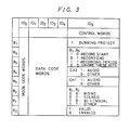
- control data words ID0 to ID5 are each formed of eight bits B0 to B7.
- the control data words ID0 to ID4 are allocated to utility word data.
- word ID0 may be a mode code and, on the basis of the value of such control data word ID0, the words ID1 to ID4 are made to selectively represent a tape count or distance along the tape, a program number, the data and day of the week when recording is being effected, the hour, minute, second and frame of the recording, a table of contents and a control code for the multi-PCM mode.
- bit B7 of word ID5 represents the dubbing protect mode, for example, dubbing is to be prevented when bit B7 is at a high level or "1".
- Bits B5 and B6 represent start and stop information, for example, as shown on Fig. 3, the record start point is indicated when bit B5 is “1” and B6 is "0”, the record end point is indicated when B5 is “0” and B6 is "1", both bits B5 and B6 are "1" between the recording start and end points, and both bits B5 and B6 are "0” to indicate that these bits are to be ignored.
- Bits B3 and B4 represent the nature of information recorded in channels CH1 and CH2, respectively.
- bit B3 or B4 is “1" when the audio signals are recorded in the respective channel CH1 or CH2, and the bit B3 or B4 is "0" when the respective channel has other information signals recorded therein.
- Bits B1 and B2 indicate the recording mode, for example, as shown, monaural sound is recorded in both channels when B1 and B2 are both "0", stereo sound is recorded (L in channel CH1 and R in channel CH2) when B1 is “0" and B2 is "1", bi-lingual recording is effected when B1 is “1” and B2 is "0", with channel CH1 receiving the main or basic sound and channel CH2 receiving the secondary sound or translation, and other modes of recording are indicated when B1 and B2 are both "1".
- the bit B0 indicates the validity or invalidity of all of the other bits B1 to B7 of word ID5. For example, the following bits B1 to B7 are valid when B0 is “1", and B0 is “1” should be written at least once per second.
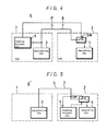
- a copying or reproducing and recording system 6 generally comprises video tape recorders (VTRs) 1 and 2 which are of the so-called 8-mm VTR-type and may be constructed integrally as a unitary structure or provided separately and connected via a cable.
- the VTR 1 is essentially a reproducing VTR and the VTR 2 is a recording VTR.
- the VTRs 1 and 2 may be provided with the same construction which includes a recording circuit and a reproducing circuit even though both of those circuits are not used in each VTR.
- each of the VTRs 1 and 2 further includes a rotary magnetic head to record either a digital audio signal alone, or together with a video signal, in oblique tracks on a magnetic tape and to reproduce the same from the magnetic tape.
- the system 6 according to this invention further includes a switch SW, which in the embodiment of Fig. 4, is provided in the recording VTR 2 as a signal recording prevention circuit.
- the digital audio signal and the video signal recorded on a master or other tape being placed therein are reproduced by the rotary magnetic head and then fed to reproducing circuit 3.
- the reproduced digital audio signal alone or with the video signal are applied from reproducing circuit 3 through a transmission line 7 to the switch SW in VTR 2 and then to the recording circuit 4.
- the digital audio signal from recording circuit 4 is recorded in oblique tracks on a slave tape by the rotary magnetic head of VTR 2.
- the dubbing protect control signal generating circuit 5′ may be provided in the recording VTR 2, as shown in Fig. 5.
- the transmission line 7 for the reproduced video and audio signals S is provided between VTRs 1 and 2 and the bit B7 in word ID5 is detected in the dubbing protect control signal generating circuit 5 in VTR 2.
- the resulting dubbing protect control signal P is applied to switch SW in VTR 2 to open the same and thereby prevent the reproduced signal S from reaching the recording circuit 4.
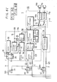
- Figs. 6I and 6II show, in greater detail, practical circuit arrangements for the master VTR 1 and the slave VTR 2 represented only generally on Fig. 4, it will be seen that the VTRs 1 and 2 may be similar with the parts of VTR 2 which correspond to those in VTR 1 being identified by the same reference numerals but with primes appended thereto. Further, only the connections between VTRs 1 and 2 drawn in bold or heavy lines are used when the system according to this invention is authorized to record in slave VTR 2 the signals being reproduced in master VTR 1.
- each of the VTRs 1 and 2 is provided with a dubbing protect control signal generating circuit 24 or 24′ and a signal recording prevention circuit SWA,SWV or SWA′,SWV′ in addition to recording and reproducing circuits.
- master VTR 1 is provided with recording/reproducing rotary magnetic heads Ha and Hb.
- a recording/reproducing block 10 is provided with recording/reproducing amplifiers 11a and 11b and a recording/reproducing change-over switch 13.
- the rotary magnetic heads Ha and Hb are respectively connected to recording/reproducing amplifiers lla and llb which are, in turn, connected selectively through change-over switch 13 to an FM-modulator/demodulator 12 or a video signal processor circuit 15 in a video block 14.
- a switch signal a (Fig. 7A) is applied to head change-over switch 13 for controlling the latter.
- a video signal input terminal VI and a video signal output terminal VO are connected with video signal processor circuit 15.
- a digital processor block 16 for processing an audio signal is shown to include a circuit 17 for effecting error correction, mean-value interpolation and 10-8 bit converting, an A/D (analog-to-digital) converter 18, a D/A (digital-to-analog) ccnverter 19 and memories 20 and 21.
- the FM-modulator/FM-demodulator 12 is connected to the error correction mean-value interpolation/10-8 bit converting circuit 17 which is, in turn, connected with A/D converter 18, D/A converter 19 and memories 20 and 21.
- a noise reduction block 22 is provided with an analog noise reduction circuit 23 which is connected to A/D converter 18 and D/A converter 19.
- An audio signal input terminal AI and an audio signal output terminal AO are connected with analog noise reduction circuit 23.
- VTR 1 is provided with a circuit 24 for generating a dubbing protect control signal, and which includes a control word data memory 25 connected to error correction/mean-value interpolation/10-8 bit converting circuit 17.
- the output read from memory 25 is supplied to a detection circuit 26 for detecting the bit data B7 of control word ID5.
- the output from detection circuit 26 is supplied to an up/down counter 27 which receives, as a clock signal, a field timing signal b (having a frequency of 60 Hz) from a terminal 28.
- a parallel output from counter 27 is supplied to a decoder 29.
- the output from decoder 29 is supplied to a D input terminal of a D flip-flop circuit 30 which also receives at its clock input terminal CK, the field timing signal b from terminal 28 and, at its set terminal S, a voltage relating to a power source voltage from a terminal 31.
- a dubbing control signal output terminal DO is led out of the non-inverting output terminal Q of flip-flop circuit 30.
- On-off switches SWA and SWV are provided in VTR 1 to respectively interrupt the digital audio signal and the video signal when VTR 1 is used for recording.
- On-off switches SWA and SWV are respectively interposed between audio signal input terminal AI and analog noise reduction circuit 23 and between the video signal input terminal VI and video signal processor circuit 15.
- VTR 1 The signal from a dubbing control signal input terminal DI is supplied through an inverter IV to switches SWA and SWV to control the opening and closing thereof.
- input terminals DI,AI and switches SWA,SWV are not used.
- VTR 2 includes all of the above described elements or parts of VTR 1 identified by the same reference numerals, but with primes appended thereto.
- VTR 2 is used as a slave VTR for recording on a second or slave tape signals reproduced from the master tape by VTR 1
- dubbing control signal output terminal DO of VTR 1 is connected to dubbing control signal input terminal DI′ of VTR 2
- audio and video output terminals AO and VO of VTR 1 are connected to the audio and video input terminal A′ and VI′, respectively, of VTR 2.
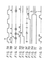
- Fig. 7A shows a switching signal a having the frequency of 30 Hz and which is used to control head change-over switch 13.
- Fig 7B shows a field timing signal b having the frequency of 60 Hz and which is applied to terminal 28. This field timing signal b is synchronized with the switching signal a shown in Fig. 7A.
- Fig. 7C represents a reproduced digital audio signal c that is obtained from audio signal output terminal AO of the reproducing or master VTR 1.
- the digital audio signal and the control word data recorded on the master tape are reproduced by reproducing VTR 1.
- the control or identification word data d (Fig. 7D) in the reproduced signal is stored on ID memory 25 of VTR 1. If the bit data B7 of the control word ID5 in the control word data stored in ID memory 25 is "1" (that is, at a high level), this fact is detected by detecting circuit 26.
- circuit 26 provides a detected output e (Fig. 7E) to an enable input terminal of counter 27.
- the enabled counter 27 starts counting the field timing signal b and the counted value thereof is changed in the order of 0,1,2,...n,...m, as shown in Fig. 7F.
- the counted value of counter 27 is decoded by decoder 29.
- decoder 29 When the decoded value becomes larger than n (n is an integer of sufficiently large value), that is, when bit B7 of word ID5 has been detected to be "1" for a predetermined number n of field periods, decoder 29 generates an output g (Fig. 7G) which is fed to the D input terminal of flip-flop circuit 30.
- the reason counter 27 is made to count the field timing signal b more than n times before decoder 29 generates output g, is to ensure that bit data B7 will not be erroneously detected by circuit 24 due to noise or the like.
- Flip-flop 30 is set by the voltage applied to terminal 31 each time the power switch of VTR l is turned ON.
- the non-inverting output h and the inverting output i, from terminal Q and Q, respectively, of flip-flop circuit 30 are reversed in level, as shown in Figs. 7H and 7I, when bit B7 of word ID5 is detected to be "1" for a predetermined time.
- the output h, which constitutes the dubbing protect control signal (Fig. 7H) is derived at dubbing protect control signal output terminal DO of VTR 1 and is supplied therefrom to input terminal DI′ of recording VTR 2 (Fig. 6II). From input terminal DI′, the dubbing protect control signal h is applied through inverter IV′ to switches SWA′ and SWV′, as a switch control signal therefor.
- the digital audio signal c (Fig 7C) and the video signal j (Fig. 7J) are not supplied to the analog noise reduction circuit 23 and the video signal processor circuit 15′ of recording VTR 2.
- the digital audio signal (including the control word data) reproduced from the master tape by the reproducing VTR 1 can not be recorded on the slave tape by the recording VTR 2 in the dubbing record mode.
- the video signal can not be recorded in the dubbing record mode.
- bit B7 of control word ID5 is detected by detector 26 to be "0"
- counter 27 is not enabled and does not count the clock signal b at the field frequency so that the output g from decoder 29 remains low and does not trigger flip-flop 30.
- the dubbing protect control signal h obtained at the Q output of flip-flop 30 remains high.
- Such dubbing protect control signal applied to input terminal DI of the recording VTR 2 causes switches SWA′ and SWV′ to remain in their closed or ON positions with the result that the digital audio signal and the video signal being reproduced in VTR 1 can be recorded on the slave tape by VTR 2 in the dubbing record mode of the system.
- the status of bit B7 of the control word ID5 recorded on the master tape determines whether or not the associated digital audio signal, or the associated digital audio signal and video signal, can be recorded on the slave tape in the dubbing record mode of the system.
- the dubbing protect control data is the bit B7 of word ID5 in the above-described embodiment
- the dubbing protect control data may be any part of the digital signal, the analog signal, the video signal, the audio signal or the data signal, but it is desirable to use data mixed into a portion of the arbitrary PCM data as at least the control data.
- this invention can be applied to a so-called multi-segment PCM VTR which employs a VTR having an 8-mm format as an apparatus for recording and reproducing only a PCM audio signal.
Landscapes
- Engineering & Computer Science (AREA)
- Signal Processing (AREA)
- Multimedia (AREA)
- Computer Security & Cryptography (AREA)
- Signal Processing For Digital Recording And Reproducing (AREA)
- Television Signal Processing For Recording (AREA)
- Signal Processing Not Specific To The Method Of Recording And Reproducing (AREA)
- Management Or Editing Of Information On Record Carriers (AREA)
Applications Claiming Priority (2)
| Application Number | Priority Date | Filing Date | Title |
|---|---|---|---|
| JP60272995A JPH0743825B2 (ja) | 1985-12-04 | 1985-12-04 | ダビング方式 |
| JP272995/85 | 1985-12-04 |
Publications (2)
| Publication Number | Publication Date |
|---|---|
| EP0224929A2 true EP0224929A2 (fr) | 1987-06-10 |
| EP0224929A3 EP0224929A3 (fr) | 1987-10-07 |
Family
ID=17521682
Family Applications (1)
| Application Number | Title | Priority Date | Filing Date |
|---|---|---|---|
| EP86116894A Withdrawn EP0224929A3 (fr) | 1985-12-04 | 1986-12-04 | Appareil et méthode pour prévenir la prise non autorisée de copies d'un signal enregistré |
Country Status (5)
| Country | Link |
|---|---|
| US (1) | US4775901A (fr) |
| EP (1) | EP0224929A3 (fr) |
| JP (1) | JPH0743825B2 (fr) |
| KR (1) | KR870006511A (fr) |
| CA (1) | CA1272800A (fr) |
Cited By (18)
| Publication number | Priority date | Publication date | Assignee | Title |
|---|---|---|---|---|
| AU577011B2 (en) * | 1985-04-17 | 1988-09-08 | Macrovision Corporation | Video signal processor for prohibiting vtr recording |
| DE3806411A1 (de) * | 1988-02-29 | 1989-09-07 | Thomson Brandt Gmbh | Verfahren zur uebertragung eines tonsignals und eines zusatzsignals |
| DE3806414A1 (de) * | 1988-02-29 | 1989-09-07 | Thomson Brandt Gmbh | Verfahren fuer einen kopierschutz bei recordern |
| WO1989008915A1 (fr) * | 1988-03-18 | 1989-09-21 | Imperial College Of Science, Technology & Medicine | Systeme de securite pour donnees numeriques |
| EP0297242A3 (en) * | 1987-06-30 | 1989-10-18 | Kabushiki Kaisha Toshiba | Recording/reproducing system with record restriction function |
| EP0418964A1 (fr) * | 1989-09-21 | 1991-03-27 | Koninklijke Philips Electronics N.V. | Support d'enregistrement, méthode et dispositif d'enregistrement d'information pour obtenir de tels supports d'information, et dispositif d'enregistrement d'information comprenant des moyens anti-copie pour empêcher des copies non autorisées |
| GB2254952A (en) * | 1991-04-19 | 1992-10-21 | Samsung Electronics Co Ltd | A system for controlling the recording of a copy protected video signal. |
| US5185792A (en) * | 1988-02-10 | 1993-02-09 | Matsushita Electric Industrial Co., Ltd. | Recording and reproducing apparatus with limited digital copying |
| US5231546A (en) * | 1988-02-10 | 1993-07-27 | Matsushita Electric Industrial Co., Ltd. | Recording and reproducing apparatus with limited digital copying |
| EP0297539B1 (fr) * | 1987-06-30 | 1993-09-01 | Kabushiki Kaisha Toshiba | Appareil pour la commande de l'enregistrement |
| EP0328141B1 (fr) * | 1988-02-10 | 1993-12-15 | Matsushita Electric Industrial Co., Ltd. | Appareil d'enregistrement et de reproduction |
| EP0581227A3 (fr) * | 1992-07-28 | 1994-03-09 | Hitachi Ltd | |
| US5337157A (en) * | 1992-01-16 | 1994-08-09 | Sony Corporation | Copy guard processing detecting apparatus |
| EP0580367A3 (en) * | 1992-07-24 | 1994-08-17 | Sony Corp | Video signal transmission, recording and reproduction |
| EP0675646A3 (fr) * | 1994-03-27 | 1996-03-13 | Sony Corp | Dispositif de traitement de signal vidéo. |
| RU2139639C1 (ru) * | 1993-03-18 | 1999-10-10 | Макровижн Корпорейшн | Способ защиты от копирования для гибридной цифровой видеозаписи на пленке и для незащищенного исходного материала и устройство для осуществления способа |
| US7792293B2 (en) | 2005-05-06 | 2010-09-07 | Rovi Solutions Corporation | Method and apparatus for modifying a subsequently generated control command in a content control system |
| US8355621B2 (en) | 2004-10-28 | 2013-01-15 | Rovi Solutions Corporation | Content management for a video signal |
Families Citing this family (75)
| Publication number | Priority date | Publication date | Assignee | Title |
|---|---|---|---|---|
| DE3851724T2 (de) * | 1987-07-08 | 1995-05-04 | Matsushita Electric Ind Co Ltd | Verfahren und Gerät zum Schutz von Kopiersignalen. |
| NL8801275A (nl) * | 1988-05-18 | 1989-12-18 | Philips Nv | Optekensysteem alsmede registratiedrager en schrijfinrichting voor toepassing in het systeem. |
| NL8901712A (nl) * | 1989-01-30 | 1990-08-16 | Philips Nv | Longitudinaal magneetband recording systeem alsmede een magneetbandapparaat geschikt voor toepassing in het systeem alsmede een magneetkop geschikt voor toepassing in het magneetbandapparaat. |
| US5247399A (en) * | 1989-05-15 | 1993-09-21 | Mitsubishi Denki Kabushiki Kaisha | Digital video recording and playback apparatus using different read and write operations for each individual memory |
| US5134496A (en) * | 1989-05-26 | 1992-07-28 | Technicolor Videocassette Of Michigan Inc. | Bilateral anti-copying device for video systems |
| KR940008688B1 (ko) * | 1989-09-08 | 1994-09-24 | 마쯔시다덴기산교 가부시기가이샤 | 정보기록장치 |
| JP2751533B2 (ja) * | 1990-02-26 | 1998-05-18 | ソニー株式会社 | 記録制御装置 |
| KR940001789B1 (ko) * | 1991-01-31 | 1994-03-05 | 삼성전자 주식회사 | 기록정보 표시장치 및 억세스 방법 |
| JP3114263B2 (ja) * | 1991-07-29 | 2000-12-04 | ソニー株式会社 | 映像信号記録システム |
| US5319735A (en) * | 1991-12-17 | 1994-06-07 | Bolt Beranek And Newman Inc. | Embedded signalling |
| FR2692092B1 (fr) * | 1992-06-05 | 1994-07-22 | Thomson Csf | Dispositif de traitement et de precorrection d'un signal audiofrequence avant son amplification dans une chaine d'amplification d'un emetteur a modulation d'amplitude. |
| US5721788A (en) | 1992-07-31 | 1998-02-24 | Corbis Corporation | Method and system for digital image signatures |
| US6301369B2 (en) | 1992-07-31 | 2001-10-09 | Digimarc Corporation | Image marking to permit later identification |
| US5589944A (en) * | 1993-06-10 | 1996-12-31 | Young; Philip L. | Method and apparatus for generating a video signal producing an unviewable display from a videotape recording thereof |
| US6944298B1 (en) | 1993-11-18 | 2005-09-13 | Digimare Corporation | Steganographic encoding and decoding of auxiliary codes in media signals |
| US7044395B1 (en) | 1993-11-18 | 2006-05-16 | Digimarc Corporation | Embedding and reading imperceptible codes on objects |
| USRE40919E1 (en) * | 1993-11-18 | 2009-09-22 | Digimarc Corporation | Methods for surveying dissemination of proprietary empirical data |
| US5748763A (en) | 1993-11-18 | 1998-05-05 | Digimarc Corporation | Image steganography system featuring perceptually adaptive and globally scalable signal embedding |
| US5841978A (en) * | 1993-11-18 | 1998-11-24 | Digimarc Corporation | Network linking method using steganographically embedded data objects |
| US6580819B1 (en) | 1993-11-18 | 2003-06-17 | Digimarc Corporation | Methods of producing security documents having digitally encoded data and documents employing same |
| US7171016B1 (en) | 1993-11-18 | 2007-01-30 | Digimarc Corporation | Method for monitoring internet dissemination of image, video and/or audio files |
| US6424725B1 (en) | 1996-05-16 | 2002-07-23 | Digimarc Corporation | Determining transformations of media signals with embedded code signals |
| US5710834A (en) * | 1995-05-08 | 1998-01-20 | Digimarc Corporation | Method and apparatus responsive to a code signal conveyed through a graphic image |
| US6516079B1 (en) | 2000-02-14 | 2003-02-04 | Digimarc Corporation | Digital watermark screening and detecting strategies |
| US6611607B1 (en) | 1993-11-18 | 2003-08-26 | Digimarc Corporation | Integrating digital watermarks in multimedia content |
| US5768426A (en) | 1993-11-18 | 1998-06-16 | Digimarc Corporation | Graphics processing system employing embedded code signals |
| US6983051B1 (en) | 1993-11-18 | 2006-01-03 | Digimarc Corporation | Methods for audio watermarking and decoding |
| ATE287176T1 (de) * | 1993-11-18 | 2005-01-15 | Digimarc Corp | Video mit versteckten in-band digitalen daten |
| US5822436A (en) * | 1996-04-25 | 1998-10-13 | Digimarc Corporation | Photographic products and methods employing embedded information |
| US6408082B1 (en) | 1996-04-25 | 2002-06-18 | Digimarc Corporation | Watermark detection using a fourier mellin transform |
| US5862260A (en) * | 1993-11-18 | 1999-01-19 | Digimarc Corporation | Methods for surveying dissemination of proprietary empirical data |
| US5841886A (en) * | 1993-11-18 | 1998-11-24 | Digimarc Corporation | Security system for photographic identification |
| US5748783A (en) * | 1995-05-08 | 1998-05-05 | Digimarc Corporation | Method and apparatus for robust information coding |
| US5832119C1 (en) * | 1993-11-18 | 2002-03-05 | Digimarc Corp | Methods for controlling systems using control signals embedded in empirical data |
| US6449377B1 (en) | 1995-05-08 | 2002-09-10 | Digimarc Corporation | Methods and systems for watermark processing of line art images |
| US5636292C1 (en) * | 1995-05-08 | 2002-06-18 | Digimarc Corp | Steganography methods employing embedded calibration data |
| US6614914B1 (en) | 1995-05-08 | 2003-09-02 | Digimarc Corporation | Watermark embedder and reader |
| US6757406B2 (en) | 1993-11-18 | 2004-06-29 | Digimarc Corporation | Steganographic image processing |
| US6122403A (en) * | 1995-07-27 | 2000-09-19 | Digimarc Corporation | Computer system linked by using information in data objects |
| US6869023B2 (en) | 2002-02-12 | 2005-03-22 | Digimarc Corporation | Linking documents through digital watermarking |
| US6968057B2 (en) | 1994-03-17 | 2005-11-22 | Digimarc Corporation | Emulsion products and imagery employing steganography |
| US6522770B1 (en) | 1999-05-19 | 2003-02-18 | Digimarc Corporation | Management of documents and other objects using optical devices |
| US7039214B2 (en) | 1999-11-05 | 2006-05-02 | Digimarc Corporation | Embedding watermark components during separate printing stages |
| US6560349B1 (en) | 1994-10-21 | 2003-05-06 | Digimarc Corporation | Audio monitoring using steganographic information |
| CN1312549C (zh) * | 1995-02-13 | 2007-04-25 | 英特特拉斯特技术公司 | 用于安全交易管理和电子权利保护的系统和方法 |
| US6728390B2 (en) | 1995-05-08 | 2004-04-27 | Digimarc Corporation | Methods and systems using multiple watermarks |
| US6760463B2 (en) * | 1995-05-08 | 2004-07-06 | Digimarc Corporation | Watermarking methods and media |
| US7486799B2 (en) | 1995-05-08 | 2009-02-03 | Digimarc Corporation | Methods for monitoring audio and images on the internet |
| US6721440B2 (en) | 1995-05-08 | 2004-04-13 | Digimarc Corporation | Low visibility watermarks using an out-of-phase color |
| US7006661B2 (en) * | 1995-07-27 | 2006-02-28 | Digimarc Corp | Digital watermarking systems and methods |
| US6408331B1 (en) | 1995-07-27 | 2002-06-18 | Digimarc Corporation | Computer linking methods using encoded graphics |
| US6829368B2 (en) | 2000-01-26 | 2004-12-07 | Digimarc Corporation | Establishing and interacting with on-line media collections using identifiers in media signals |
| US6577746B1 (en) | 1999-12-28 | 2003-06-10 | Digimarc Corporation | Watermark-based object linking and embedding |
| US6788800B1 (en) | 2000-07-25 | 2004-09-07 | Digimarc Corporation | Authenticating objects using embedded data |
| US6411725B1 (en) | 1995-07-27 | 2002-06-25 | Digimarc Corporation | Watermark enabled video objects |
| US6965682B1 (en) | 1999-05-19 | 2005-11-15 | Digimarc Corp | Data transmission by watermark proxy |
| JP3613858B2 (ja) * | 1995-10-26 | 2005-01-26 | ソニー株式会社 | テレビジョン信号の伝送または記録方法、および記録装置 |
| US6381341B1 (en) | 1996-05-16 | 2002-04-30 | Digimarc Corporation | Watermark encoding method exploiting biases inherent in original signal |
| US7054463B2 (en) | 1998-01-20 | 2006-05-30 | Digimarc Corporation | Data encoding using frail watermarks |
| US6625297B1 (en) | 2000-02-10 | 2003-09-23 | Digimarc Corporation | Self-orienting watermarks |
| EP1143722B1 (fr) * | 2000-04-07 | 2008-11-05 | Irdeto Access B.V. | Système d'enchiffrage et de déchiffrage des données |
| US7027614B2 (en) | 2000-04-19 | 2006-04-11 | Digimarc Corporation | Hiding information to reduce or offset perceptible artifacts |
| US6804377B2 (en) | 2000-04-19 | 2004-10-12 | Digimarc Corporation | Detecting information hidden out-of-phase in color channels |
| US6817530B2 (en) | 2001-12-18 | 2004-11-16 | Digimarc Id Systems | Multiple image security features for identification documents and methods of making same |
| US7793846B2 (en) | 2001-12-24 | 2010-09-14 | L-1 Secure Credentialing, Inc. | Systems, compositions, and methods for full color laser engraving of ID documents |
| US7694887B2 (en) | 2001-12-24 | 2010-04-13 | L-1 Secure Credentialing, Inc. | Optically variable personalized indicia for identification documents |
| ATE552120T1 (de) | 2001-12-24 | 2012-04-15 | L 1 Secure Credentialing Inc | Verdeckte variableninformationen auf id- dokumenten und verfahren zu ihrer herstellung |
| US7728048B2 (en) | 2002-12-20 | 2010-06-01 | L-1 Secure Credentialing, Inc. | Increasing thermal conductivity of host polymer used with laser engraving methods and compositions |
| US7824029B2 (en) | 2002-05-10 | 2010-11-02 | L-1 Secure Credentialing, Inc. | Identification card printer-assembler for over the counter card issuing |
| US7804982B2 (en) | 2002-11-26 | 2010-09-28 | L-1 Secure Credentialing, Inc. | Systems and methods for managing and detecting fraud in image databases used with identification documents |
| US7712673B2 (en) | 2002-12-18 | 2010-05-11 | L-L Secure Credentialing, Inc. | Identification document with three dimensional image of bearer |
| DE602004030434D1 (de) | 2003-04-16 | 2011-01-20 | L 1 Secure Credentialing Inc | Dreidimensionale datenspeicherung |
| US7744002B2 (en) | 2004-03-11 | 2010-06-29 | L-1 Secure Credentialing, Inc. | Tamper evident adhesive and identification document including same |
| WO2015189994A1 (fr) * | 2014-06-13 | 2015-12-17 | 株式会社日立システムズ | Dispositif d'enregistrement d'opération, système d'enregistrement d'opération, programme d'enregistrement d'opération et procédé d'enregistrement d'opération |
| US10348907B1 (en) * | 2016-05-12 | 2019-07-09 | Antony P. Ng | Collaborative data processing |
Family Cites Families (9)
| Publication number | Priority date | Publication date | Assignee | Title |
|---|---|---|---|---|
| FR2459532B1 (fr) * | 1979-06-18 | 1987-07-31 | Quadrivium Tech Avancees | Procede pour associer une information auxiliaire a une information principale enregistree et application au controle de la reproduction d'information enregistree |
| JPS5630340A (en) * | 1979-08-20 | 1981-03-26 | Sony Corp | Digital signal transmitting method |
| GB2104701B (en) * | 1981-08-06 | 1985-06-05 | James Bertram King | Method and apparatus for preventing unauthorised recording of source material (eg, a gramophone recording) |
| JPS601660A (ja) * | 1983-06-17 | 1985-01-07 | Mitsubishi Electric Corp | ダビングプロテクト装置 |
| AU3613684A (en) * | 1983-11-21 | 1985-06-03 | Haute Securite Video Hsv S.A. | Procede et dispositif anti-piraterie pour supports d'images cinematographiques et video |
| US4622600A (en) * | 1983-12-26 | 1986-11-11 | Hitachi, Ltd. | Rotary-head type PCM data recording/reproducing method and apparatus with a redundancy-reduced control data format |
| NL8400619A (nl) * | 1984-02-28 | 1985-09-16 | Alfred Struik | Beeld-geluidstelsel. |
| JPS60173142U (ja) * | 1984-04-20 | 1985-11-16 | 三洋電機株式会社 | テ−プレコ−ダ |
| JPS6275901A (ja) * | 1985-09-27 | 1987-04-07 | Nec Home Electronics Ltd | 記録再生装置の複製禁止装置 |
-
1985
- 1985-12-04 JP JP60272995A patent/JPH0743825B2/ja not_active Expired - Lifetime
-
1986
- 1986-11-25 CA CA000523718A patent/CA1272800A/fr not_active Expired - Lifetime
- 1986-12-02 US US06/937,017 patent/US4775901A/en not_active Expired - Lifetime
- 1986-12-03 KR KR860010307A patent/KR870006511A/ko not_active Withdrawn
- 1986-12-04 EP EP86116894A patent/EP0224929A3/fr not_active Withdrawn
Cited By (29)
| Publication number | Priority date | Publication date | Assignee | Title |
|---|---|---|---|---|
| AU577011B2 (en) * | 1985-04-17 | 1988-09-08 | Macrovision Corporation | Video signal processor for prohibiting vtr recording |
| EP0297242A3 (en) * | 1987-06-30 | 1989-10-18 | Kabushiki Kaisha Toshiba | Recording/reproducing system with record restriction function |
| US4924328A (en) * | 1987-06-30 | 1990-05-08 | Kabushiki Kaisha Toshiba | System for recording/reproducing an information source having an apparatus-specific identification signal |
| EP0297539B1 (fr) * | 1987-06-30 | 1993-09-01 | Kabushiki Kaisha Toshiba | Appareil pour la commande de l'enregistrement |
| US5231546A (en) * | 1988-02-10 | 1993-07-27 | Matsushita Electric Industrial Co., Ltd. | Recording and reproducing apparatus with limited digital copying |
| EP0328141B1 (fr) * | 1988-02-10 | 1993-12-15 | Matsushita Electric Industrial Co., Ltd. | Appareil d'enregistrement et de reproduction |
| US5185792A (en) * | 1988-02-10 | 1993-02-09 | Matsushita Electric Industrial Co., Ltd. | Recording and reproducing apparatus with limited digital copying |
| DE3806411A1 (de) * | 1988-02-29 | 1989-09-07 | Thomson Brandt Gmbh | Verfahren zur uebertragung eines tonsignals und eines zusatzsignals |
| DE3806414A1 (de) * | 1988-02-29 | 1989-09-07 | Thomson Brandt Gmbh | Verfahren fuer einen kopierschutz bei recordern |
| WO1989008915A1 (fr) * | 1988-03-18 | 1989-09-21 | Imperial College Of Science, Technology & Medicine | Systeme de securite pour donnees numeriques |
| EP0418964A1 (fr) * | 1989-09-21 | 1991-03-27 | Koninklijke Philips Electronics N.V. | Support d'enregistrement, méthode et dispositif d'enregistrement d'information pour obtenir de tels supports d'information, et dispositif d'enregistrement d'information comprenant des moyens anti-copie pour empêcher des copies non autorisées |
| GB2254952A (en) * | 1991-04-19 | 1992-10-21 | Samsung Electronics Co Ltd | A system for controlling the recording of a copy protected video signal. |
| GB2254952B (en) * | 1991-04-19 | 1995-02-15 | Samsung Electronics Co Ltd | A system for controlling the recording of a copy protected video signal |
| US5337157A (en) * | 1992-01-16 | 1994-08-09 | Sony Corporation | Copy guard processing detecting apparatus |
| EP0580367A3 (en) * | 1992-07-24 | 1994-08-17 | Sony Corp | Video signal transmission, recording and reproduction |
| EP0830024A3 (fr) * | 1992-07-24 | 1998-11-11 | Sony Corporation | Transmission, enregistrement et reproduction d'un signal vidéo |
| US5418853A (en) * | 1992-07-24 | 1995-05-23 | Sony Corporation | Apparatus and method for preventing unauthorized copying of video signals |
| USRE36763E (en) * | 1992-07-24 | 2000-07-04 | Sony Corporation | Apparatus and method for preventing unauthorized copying of video signals |
| CN1042286C (zh) * | 1992-07-24 | 1999-02-24 | 索尼公司 | 防止未经允许地复制视频信号的方法和装置 |
| EP0830025A3 (fr) * | 1992-07-24 | 1998-11-11 | Sony Corporation | Transmission, enregistrement et reproduction d'un signal vidéo |
| US5627655A (en) * | 1992-07-28 | 1997-05-06 | Hitachi, Ltd. | Recording apparatus and reproducing apparatus for video signals |
| US5778140A (en) * | 1992-07-28 | 1998-07-07 | Hitachi, Ltd. | Video signal processing apparatus |
| EP0581227A3 (fr) * | 1992-07-28 | 1994-03-09 | Hitachi Ltd | |
| RU2139639C1 (ru) * | 1993-03-18 | 1999-10-10 | Макровижн Корпорейшн | Способ защиты от копирования для гибридной цифровой видеозаписи на пленке и для незащищенного исходного материала и устройство для осуществления способа |
| US5668873A (en) * | 1994-03-27 | 1997-09-16 | Sony Corporation | Video signal processor with copy prevention function |
| EP0675646A3 (fr) * | 1994-03-27 | 1996-03-13 | Sony Corp | Dispositif de traitement de signal vidéo. |
| US8355621B2 (en) | 2004-10-28 | 2013-01-15 | Rovi Solutions Corporation | Content management for a video signal |
| US7792293B2 (en) | 2005-05-06 | 2010-09-07 | Rovi Solutions Corporation | Method and apparatus for modifying a subsequently generated control command in a content control system |
| US8374347B2 (en) | 2005-05-06 | 2013-02-12 | Rovi Solutions Corporation | Method and apparatus for modifying a subsequently generated control command in a content control system |
Also Published As
| Publication number | Publication date |
|---|---|
| JPH0743825B2 (ja) | 1995-05-15 |
| EP0224929A3 (fr) | 1987-10-07 |
| JPS62132233A (ja) | 1987-06-15 |
| US4775901A (en) | 1988-10-04 |
| KR870006511A (ko) | 1987-07-11 |
| CA1272800A (fr) | 1990-08-14 |
Similar Documents
| Publication | Publication Date | Title |
|---|---|---|
| US4775901A (en) | Apparatus and method for preventing unauthorized dubbing of a recorded signal | |
| US4910736A (en) | Encoding method and apparatus for recording data with an identification code and an error check code | |
| GB2044586A (en) | Recording digital data error correction | |
| US4604657A (en) | Apparatus for processing PCM signal | |
| EP0209141A2 (fr) | Appareil d'enregistrement et de reproduction de signaux MIC | |
| CA1232965A (fr) | Lecteur de disques magnetiques | |
| JPS607651A (ja) | デイジタル情報信号の記録装置 | |
| EP0335273B1 (fr) | Système d'enregistrement et de reproduction de signaux audio numériques | |
| KR100196586B1 (ko) | 디지탈 신호 처리 회로 | |
| JPH0583986B2 (fr) | ||
| EP0053505B1 (fr) | Appareil de traitement de signal modulé par impulsions codées | |
| US5655050A (en) | Apparatus and method for recording and reproducing digital signal in synchronization blocks | |
| EP0336424B1 (fr) | Appareil de reproduction de signaux de données pour un enregistrement à balayage hélicoidal | |
| KR0138119B1 (ko) | 디지털 신호 재생장치 | |
| KR910008396B1 (ko) | 메모리 제어장치 | |
| US5228041A (en) | Sync signal detection system in a memory system for recording and reproducing block unit data | |
| JP2778169B2 (ja) | デイジタル信号処理回路 | |
| EP0364961B1 (fr) | Circuit de détection d'erreur d'enregistrement et appareil d'enregistrement et de reproduction | |
| JPH0319106A (ja) | 情報記録再生装置 | |
| KR910003378B1 (ko) | 디지탈 신호 복조 및 재생장치 | |
| JPS6329347B2 (fr) | ||
| US5253257A (en) | Recording error detector circuit and recording reproducing apparatus | |
| US4870647A (en) | Digital signal demodulator | |
| JP2775788B2 (ja) | データ誤り検出装置 | |
| JP2576535B2 (ja) | データレコーダ |
Legal Events
| Date | Code | Title | Description |
|---|---|---|---|
| PUAI | Public reference made under article 153(3) epc to a published international application that has entered the european phase |
Free format text: ORIGINAL CODE: 0009012 |
|
| AK | Designated contracting states |
Kind code of ref document: A2 Designated state(s): DE FR GB |
|
| PUAL | Search report despatched |
Free format text: ORIGINAL CODE: 0009013 |
|
| AK | Designated contracting states |
Kind code of ref document: A3 Designated state(s): DE FR GB |
|
| 17P | Request for examination filed |
Effective date: 19871214 |
|
| 17Q | First examination report despatched |
Effective date: 19880413 |
|
| STAA | Information on the status of an ep patent application or granted ep patent |
Free format text: STATUS: THE APPLICATION IS DEEMED TO BE WITHDRAWN |
|
| 18D | Application deemed to be withdrawn |
Effective date: 19890718 |
|
| RIN1 | Information on inventor provided before grant (corrected) |
Inventor name: NAKANO, KENJIC/O SONY CORPORATION |