EP0224948A1 - Filtre de granulat - Google Patents
Filtre de granulat Download PDFInfo
- Publication number
- EP0224948A1 EP0224948A1 EP86201926A EP86201926A EP0224948A1 EP 0224948 A1 EP0224948 A1 EP 0224948A1 EP 86201926 A EP86201926 A EP 86201926A EP 86201926 A EP86201926 A EP 86201926A EP 0224948 A1 EP0224948 A1 EP 0224948A1
- Authority
- EP
- European Patent Office
- Prior art keywords
- granulate
- filter according
- piston
- pistons
- bottom part
- Prior art date
- Legal status (The legal status is an assumption and is not a legal conclusion. Google has not performed a legal analysis and makes no representation as to the accuracy of the status listed.)
- Granted
Links
- 239000008187 granular material Substances 0.000 title claims abstract description 61
- 238000011001 backwashing Methods 0.000 claims abstract description 12
- 238000004140 cleaning Methods 0.000 claims abstract description 12
- 238000000034 method Methods 0.000 claims description 8
- 238000010926 purge Methods 0.000 claims description 4
- 238000007664 blowing Methods 0.000 claims description 2
- 238000005192 partition Methods 0.000 claims description 2
- 230000000903 blocking effect Effects 0.000 claims 1
- 238000005299 abrasion Methods 0.000 abstract description 4
- 230000006835 compression Effects 0.000 description 1
- 238000007906 compression Methods 0.000 description 1
- 238000010276 construction Methods 0.000 description 1
- 238000011161 development Methods 0.000 description 1
- 230000018109 developmental process Effects 0.000 description 1
- 230000000694 effects Effects 0.000 description 1
- 238000011086 high cleaning Methods 0.000 description 1
- 239000012535 impurity Substances 0.000 description 1
- 238000012423 maintenance Methods 0.000 description 1
- 239000002245 particle Substances 0.000 description 1
- 238000010079 rubber tapping Methods 0.000 description 1
Images


Classifications
-
- B—PERFORMING OPERATIONS; TRANSPORTING
- B01—PHYSICAL OR CHEMICAL PROCESSES OR APPARATUS IN GENERAL
- B01D—SEPARATION
- B01D46/00—Filters or filtering processes specially modified for separating dispersed particles from gases or vapours
- B01D46/30—Particle separators, e.g. dust precipitators, using loose filtering material
Definitions
- the invention relates to a granulate filter for horizontal gas passage with two gas-permeable walls arranged vertically at a distance from one another, a frame consisting of a base part and two side parts, connected to the walls, and a granulate fill in the space formed by the frame and the walls, as well as a process for cleaning the granulate bed by backwashing.
- the granulate bed is cleaned outside the filter in a special cleaning chamber, the granules either being cleaned in batches at intervals or by the granules continuously circulating through the filter space and the cleaning chamber.
- cleaning processes require complex transport devices for the granulate, which are only required for a short time in batch operation and are very susceptible to faults or require maintenance because of the long downtimes and the frequent switching on and off.
- continuous circulation all affected parts of the apparatus are subject to heavy wear.
- the granules are subject to a relatively high level of abrasion through which the filters characteristics changed and an increase in the gas-side flow resistance is brought about.
- the granulate bed can be loosened by backwashing during cleaning, which makes cleaning in comparison to backwashing can be significantly improved when the granulate is not moved.
- the lifting height and lifting speed of the piston can be matched to the respective requirements, which means that an economic optimum can be achieved in each individual case, ie at the same time a high cleaning effect and low granulate wear.
- the invention provides that the granulate bed is loosened before and / or during backwashing by moving the pistons up and down.
- Advantageous variations of the method result from claims 15 to 17.
- the granulate filter for horizontal gas passage according to FIG. 1 has two gas-permeable walls l and 2 arranged vertically at a distance from one another, each with a perforated plate la, 2a and a wire screen lb, 2b matched to the granulate particles.
- the gas permeable walls l and 2 together with the upwardly open frame 3 form a space in which the granulate bed 4 is arranged.
- the wall parts and the granulate fill are only partially shown.
- perforated plate 2a, wire screen 2b, granulate bed 4, wire screen lb and perforated plate la follow one another from front to back in the illustration.
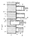
- openings 7 are arranged in the bottom part 5 of the frame 3 and can be closed in a granulate-tight manner by pistons 6 which can be moved up and down.
- the granulate bed is divided by partition walls l0 into chambers, each of which is assigned an opening 7 with a piston 6.
- the pistons are shown from the left in FIG. 2 only for the second and fourth chambers.
- FIG. 2 has a different embodiment of the piston and the piston guide for the first and second chambers than for the chambers 3 and 4. This representation has been chosen in order not to have to unnecessarily increase the number of drawings. In practice, of course, the same embodiment will be chosen for all chambers of a granulate filter.
- FIG. 3 shows a simplified view and a simplified horizontal section of the exemplary embodiment, supplemented by a drive for the pistons.
- the perforated plate la has a cover l2 in the upper part, by means of which the uppermost region of the granulate bed is blocked for the gas passage. In this way it is ensured that the gas does not have any granule-free cross-sectional areas which it could flow through uncleaned, moreover with a lower pressure drop.
- a plurality of chambers 11 are formed by intermediate walls 10 within the side walls of the frame 3, to which an opening 7 with piston guide 9a and piston 6 is assigned in each case in the base part.
- a crankshaft is provided for the up and down movement, which can be set in rotation by a drive l3.
- Such an embodiment requires that the granulate beds in all chambers of a granulate filter are simultaneously loosened, i.e. that the granulate filter is cleaned in this case overall by backwashing.
- hydraulic or pneumatic individual drives can also be provided for the pistons, so that the chambers can be cleaned one after the other in conjunction with a corresponding gas-side shut-off, the granulate filter remaining operational otherwise.
Landscapes
- Chemical & Material Sciences (AREA)
- Chemical Kinetics & Catalysis (AREA)
- Filtering Of Dispersed Particles In Gases (AREA)
- Glanulating (AREA)
- Filtration Of Liquid (AREA)
Applications Claiming Priority (2)
| Application Number | Priority Date | Filing Date | Title |
|---|---|---|---|
| DE19853541174 DE3541174A1 (de) | 1985-11-21 | 1985-11-21 | Granulatfilter |
| DE3541174 | 1985-11-21 |
Publications (2)
| Publication Number | Publication Date |
|---|---|
| EP0224948A1 true EP0224948A1 (fr) | 1987-06-10 |
| EP0224948B1 EP0224948B1 (fr) | 1989-04-19 |
Family
ID=6286477
Family Applications (1)
| Application Number | Title | Priority Date | Filing Date |
|---|---|---|---|
| EP86201926A Expired EP0224948B1 (fr) | 1985-11-21 | 1986-11-05 | Filtre de granulat |
Country Status (4)
| Country | Link |
|---|---|
| US (1) | US4702751A (fr) |
| EP (1) | EP0224948B1 (fr) |
| JP (1) | JPS62129123A (fr) |
| DE (2) | DE3541174A1 (fr) |
Families Citing this family (3)
| Publication number | Priority date | Publication date | Assignee | Title |
|---|---|---|---|---|
| US4840651A (en) * | 1988-01-11 | 1989-06-20 | Tigg Corporation | Gas/solids contacting device |
| GB2268094A (en) * | 1992-06-12 | 1994-01-05 | Stork Protecon Bv | Filter for a gas stream, especially from a fluidised bed |
| JP6559025B2 (ja) * | 2015-09-14 | 2019-08-14 | 日本製鉄株式会社 | 触媒反応装置及び触媒反応方法 |
Citations (2)
| Publication number | Priority date | Publication date | Assignee | Title |
|---|---|---|---|---|
| DE1911837A1 (de) * | 1968-03-08 | 1969-10-09 | Fuller Co | Verfahren und Vorrichtung zum Reinigen von Filterbetten |
| DE2325695A1 (de) * | 1973-05-21 | 1974-12-12 | Max Berz Einrichtungen Fuer Di | Vorrichtung zum abscheiden von staub in wenigstens einer schuettgutschicht und zum reinigen dieser schuettgutschicht |
Family Cites Families (1)
| Publication number | Priority date | Publication date | Assignee | Title |
|---|---|---|---|---|
| SU1084051A1 (ru) * | 1982-12-27 | 1984-04-07 | Волго-Уральский научно-исследовательский и проектный институт по добыче и переработке сероводородсодержащих газов | Адсорбер |
-
1985
- 1985-11-21 DE DE19853541174 patent/DE3541174A1/de not_active Withdrawn
-
1986
- 1986-11-05 EP EP86201926A patent/EP0224948B1/fr not_active Expired
- 1986-11-05 DE DE8686201926T patent/DE3662840D1/de not_active Expired
- 1986-11-18 US US06/932,190 patent/US4702751A/en not_active Expired - Fee Related
- 1986-11-19 JP JP61276395A patent/JPS62129123A/ja active Pending
Patent Citations (2)
| Publication number | Priority date | Publication date | Assignee | Title |
|---|---|---|---|---|
| DE1911837A1 (de) * | 1968-03-08 | 1969-10-09 | Fuller Co | Verfahren und Vorrichtung zum Reinigen von Filterbetten |
| DE2325695A1 (de) * | 1973-05-21 | 1974-12-12 | Max Berz Einrichtungen Fuer Di | Vorrichtung zum abscheiden von staub in wenigstens einer schuettgutschicht und zum reinigen dieser schuettgutschicht |
Also Published As
| Publication number | Publication date |
|---|---|
| EP0224948B1 (fr) | 1989-04-19 |
| DE3541174A1 (de) | 1987-05-27 |
| JPS62129123A (ja) | 1987-06-11 |
| DE3662840D1 (en) | 1989-05-24 |
| US4702751A (en) | 1987-10-27 |
Similar Documents
| Publication | Publication Date | Title |
|---|---|---|
| DE69208358T2 (de) | Vorrichtung zur gleichmässigen Verteilung von Gas und/oder Flüssigkeit in einem seitlichen Unterdrainagesystem | |
| DE3235552C2 (de) | Rückspülfilter | |
| DE2231904C3 (de) | Automatischer kontinuierlicher Gegenstromwaschfilter | |
| DE3138676A1 (de) | Filtereinrichtung mit einer einrichtung zum rueckspuelen des filterbettes | |
| DE69805008T2 (de) | Vacuumspannvorrichtung für zu bearbeitende platten | |
| EP0438685A1 (fr) | Former dans une machine à papier | |
| DE2455904C3 (de) | Vorrichtung zum Trennen eines Gemisches von Flüssigkeiten verschiedener spezifischer Gewichte | |
| DE68913136T2 (de) | Verfahren zur zyklischen Zubereitung von Käsemassensträngen und Vorrichtung zur Ausführung dieses Verfahrens. | |
| EP0224948B1 (fr) | Filtre de granulat | |
| DE1461512A1 (de) | Filterpresse | |
| DE2749487A1 (de) | Fluessigkeitsfilter | |
| EP0507783B1 (fr) | Dispositif pour la separation de composants indesirables de gaz d'echappement | |
| DE3028901C2 (fr) | ||
| DE69827215T2 (de) | Statische Anlage zum Filtern von Flüssigkeiten | |
| DE1584769C3 (de) | Verfahren und Vorrichtung zur Herstellung von Betonblöcken mit einer Oberfläche aus stückförmigem Material | |
| DE69319206T2 (de) | Anlage zum automatischen Reinigen von Plattenfilterpressen | |
| DE4215472C1 (en) | Welt filter for cleaning plastic melts - having sieve plate cut=out along the side which can hold filters in the form of ring members | |
| EP0245869B1 (fr) | Dispositif pour mélanger des matières plastiques comportant plusieurs composants, en particulier du polyuréthane | |
| EP0099528A2 (fr) | Appareil à tamiser | |
| DE8717960U1 (de) | Labyrinthfilter für das Dielektrikum von Erodieranlagen | |
| DE2460521A1 (de) | Abscheidereinrichtung | |
| DE87482C (fr) | ||
| DE2315743C3 (de) | Druckfilter | |
| EP0970788A1 (fr) | Installation et procédé de fabrication d'un mat à partir d'une masse de moulage fibreux | |
| DE3034853A1 (de) | Geraet zur kontinuierlichen zufuehrung von festkoerperpartikeln in einen druckbehaelter |
Legal Events
| Date | Code | Title | Description |
|---|---|---|---|
| PUAI | Public reference made under article 153(3) epc to a published international application that has entered the european phase |
Free format text: ORIGINAL CODE: 0009012 |
|
| AK | Designated contracting states |
Kind code of ref document: A1 Designated state(s): CH DE FR GB IT LI |
|
| 17P | Request for examination filed |
Effective date: 19870708 |
|
| 17Q | First examination report despatched |
Effective date: 19880907 |
|
| GRAA | (expected) grant |
Free format text: ORIGINAL CODE: 0009210 |
|
| AK | Designated contracting states |
Kind code of ref document: B1 Designated state(s): CH DE FR GB IT LI |
|
| REF | Corresponds to: |
Ref document number: 3662840 Country of ref document: DE Date of ref document: 19890524 |
|
| ET | Fr: translation filed | ||
| ITF | It: translation for a ep patent filed | ||
| GBT | Gb: translation of ep patent filed (gb section 77(6)(a)/1977) | ||
| PLBE | No opposition filed within time limit |
Free format text: ORIGINAL CODE: 0009261 |
|
| STAA | Information on the status of an ep patent application or granted ep patent |
Free format text: STATUS: NO OPPOSITION FILED WITHIN TIME LIMIT |
|
| 26N | No opposition filed | ||
| PGFP | Annual fee paid to national office [announced via postgrant information from national office to epo] |
Ref country code: FR Payment date: 19910917 Year of fee payment: 6 |
|
| PGFP | Annual fee paid to national office [announced via postgrant information from national office to epo] |
Ref country code: GB Payment date: 19911024 Year of fee payment: 6 |
|
| ITTA | It: last paid annual fee | ||
| PGFP | Annual fee paid to national office [announced via postgrant information from national office to epo] |
Ref country code: CH Payment date: 19911216 Year of fee payment: 6 |
|
| PG25 | Lapsed in a contracting state [announced via postgrant information from national office to epo] |
Ref country code: GB Effective date: 19921105 |
|
| PG25 | Lapsed in a contracting state [announced via postgrant information from national office to epo] |
Ref country code: LI Effective date: 19921130 Ref country code: CH Effective date: 19921130 |
|
| GBPC | Gb: european patent ceased through non-payment of renewal fee |
Effective date: 19921105 |
|
| PG25 | Lapsed in a contracting state [announced via postgrant information from national office to epo] |
Ref country code: FR Effective date: 19930730 |
|
| REG | Reference to a national code |
Ref country code: CH Ref legal event code: PL |
|
| REG | Reference to a national code |
Ref country code: FR Ref legal event code: ST |
|
| PGFP | Annual fee paid to national office [announced via postgrant information from national office to epo] |
Ref country code: DE Payment date: 19941221 Year of fee payment: 9 |
|
| PG25 | Lapsed in a contracting state [announced via postgrant information from national office to epo] |
Ref country code: DE Effective date: 19951129 |
|
| PG25 | Lapsed in a contracting state [announced via postgrant information from national office to epo] |
Ref country code: IT Free format text: LAPSE BECAUSE OF NON-PAYMENT OF DUE FEES;WARNING: LAPSES OF ITALIAN PATENTS WITH EFFECTIVE DATE BEFORE 2007 MAY HAVE OCCURRED AT ANY TIME BEFORE 2007. THE CORRECT EFFECTIVE DATE MAY BE DIFFERENT FROM THE ONE RECORDED. Effective date: 20051105 |