EP0225028A2 - Dispositif et procédé pour l'évacuation de l'humidité de groupes frigorifiques - Google Patents
Dispositif et procédé pour l'évacuation de l'humidité de groupes frigorifiques Download PDFInfo
- Publication number
- EP0225028A2 EP0225028A2 EP86308162A EP86308162A EP0225028A2 EP 0225028 A2 EP0225028 A2 EP 0225028A2 EP 86308162 A EP86308162 A EP 86308162A EP 86308162 A EP86308162 A EP 86308162A EP 0225028 A2 EP0225028 A2 EP 0225028A2
- Authority
- EP
- European Patent Office
- Prior art keywords
- pressure side
- side valve
- refrigeration unit
- gas
- low pressure
- Prior art date
- Legal status (The legal status is an assumption and is not a legal conclusion. Google has not performed a legal analysis and makes no representation as to the accuracy of the status listed.)
- Withdrawn
Links
Images
Classifications
-
- F—MECHANICAL ENGINEERING; LIGHTING; HEATING; WEAPONS; BLASTING
- F25—REFRIGERATION OR COOLING; COMBINED HEATING AND REFRIGERATION SYSTEMS; HEAT PUMP SYSTEMS; MANUFACTURE OR STORAGE OF ICE; LIQUEFACTION SOLIDIFICATION OF GASES
- F25B—REFRIGERATION MACHINES, PLANTS OR SYSTEMS; COMBINED HEATING AND REFRIGERATION SYSTEMS; HEAT PUMP SYSTEMS
- F25B47/00—Arrangements for preventing or removing deposits or corrosion, not provided for in another subclass
Definitions
- This invention relates to apparatus for and methods of removing moisture from refrigeration units.
- a refrigeration unit consists primarily of four components, namely, a compressor, a condensor, a metering device and an evaporator.
- the condensor condenses a refrigerant, such as Freon (Trade Mark) or other gaseous fluorocarbons, and provides compressed gas to the condensor.
- the condensor condenses the refrigerant and provides it through capillary tubing to the evaporator where the condensed refrigerant is evaporated thereby absorbing heat and causing a cooling effect to occur. From the evaporator, the evaporated refrigerant is provided back to the compressor where the cycle is repeated.
- a low pressure side valve or a process tube on the compressor and positioned between the condensor and the metering device is a high pressure side valve. Either of the two valves can be opened in order to allow gas to be added to the refrigeration unit or purged from the refrigeration unit.
- a strainer or dryer filter within the refrigeration unit typically positioned between the high pressure side valve and the metering device.
- Any refrigeration unit is susceptible to leaks through which moist air or other contaminants can enter into the system. Any moisture which may enter the refrigeration unit through such leaks can seriously affect the performance of the refrigeration unit. After the leak or any other repairs in the sealed refrigeration unit has been repaired, it is desirable to eliminate as much of the moisture from the refrigeration unit as possible. This typically has been done in the past by connecting a vacuum pump to the low and high pressure side valves and evacuating as much of the gas from the refrigeration unit as possible. While this procedure has proved effective in the past, it generally requires several hours to accomplish the desired result.
- apparatus for removing moisture from a refrigeration unit which comprises a compressor, a condensor and an evaporator connected in a loop, and which includes a low pressure side valve between said compressor and said evaporator and a high pressure side valve between said condenser and the evaporator
- said apparatus being characterised by: output coupling means for connection to said low pressure side valve; input coupling means for connection to a source of dry gas; gas transfer and heating means positioned between said output coupling means and said input coupling means for transferring and heating dry gas supplied through said input coupling means, to said output coupling means; sensing means for sensing the temperature and pressure of said dry gas transferred to said output coupling means; and indicating means for indicating the sensed temperature and pressure to indicate when to close said low pressure side valve.
- a method of removing moisture from a refrigeration unit which comprises a compressor, a condensor and an evaporator connected in a loop and which includes a low pressure side valve positioned between said evaporator and said compressor and a high pressure side valve positioned between said condensor and said evaporator, said method being characterised by the steps of: heating a dry gas; providing said heated dry gas through said low pressure side valve; operating said refrigeration unit; opening said high pressure side valve; and providing refrigerant through said low pressure side valve.
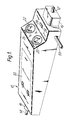
- an apparatus 10 for removing moisture from a refrigeration units includes an input pipe 12 and an outlet pipe 14.
- the pipe 12 is adapted to be coupled to a source or tank (not shown) of a dry gas.
- the gas should be of a type which does not affect the performance of the refrigerant in the refrigeration unit and may be, for example, nitrogen, helium or air.
- the gas is provided through the pipe 12 into a regulator 16 which allows the gas to pas therethrough so long as the pressure downstream of the regulator 16 is less than a predetermined value.
- the regulator 16 may be of a type which opens at 45 psi (310 kPa) and closes ad 65 psi (450 kPa).
- the pipe 14 is adapted to be coupled to a low pressure side valve 44 or process tube in a refrigeration unit ( Figure 2) and heated gas from within the apparatus 10 is provided through a safety relief valve 18 into the pipe 14.
- the safety valve 18 may be set at a maximum of 120 psi (830 kPa) so that if the pressure within the apparatus 10 ever exceeds that amount, the safety valve 18 automatically opens and allows gas to escape.
- the apparatus 10 includes a temperature gauge 20, and a pressure gauge 22 for reading the temprature and pressure of the gas in the apparatus 10 between the pipe 12 and the pipe 14. Further the apparatus 10 includes an ON/OFF switch 24 and an associated ON/OFF light 26. Further, a ready light 28 is provided to indicate to the operator that the predetermined temperature of a cylindrical heating pipe 46 ( Figure 3) has been attained. Lastly, the apparatus 10 includes a storage door 30 which can be opened to allow associated piping and fitting to be stored. Such piping may be used to couple the pipe 12 to the source of gas and/or to couple the pipe 14 to the low pressure side valve of the refrigeration unit.
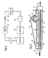
- the refrigeration unit includes a compressor 32, a condensor 34, a high pressure side valve 36, a strainer filter 38, capillary tubing 40, an evaporator 42 and a low pressure side valve 44. Both the high pressure side valve 36 and the low pressure side valve 44 are accessible to a person desiring to work with the refrigeration unit. For example, the low pressure side valve 44 may be opened to allow gas or refrigerant to be placed into the refrigeration unit and the high pressure side valve 36 may be opened to allow gas already in the refrigeration unit to be expelled therefrom.
- the heating pipe 46 Between the regulator 16 and the safety valve 18 is the heating pipe 46 on which is wound a heating coil 48.
- the heating coil 48 may be conventional strip heater or other mechanism adapted to heat the heating pipe 46.
- the valve on the source of dry gas After setting the switch 24 to the ON position, and waiting for the ready light 28 to be illuminated, thereby indicating the temperature of the heating pipe 46 is at the predetermined temperature, for example, 220°F (114°C), the valve on the source of dry gas is opened and gas flows into the heating pipe 46.
- the temperature of the heating pipe 46 is measured by a thermostat 50 located on the heating pipe adjacent the safety valve 18. Wires leading from the thermostat 50 are coupled to the temperature gauge 22 along with wires from the ends of the heating coil 48.
- a switch (not shown) disconnects current from the heating coil 48.
- the switch is closed allowing current to be applied once more to the coil 48.
- the wires from the thermostat 50 allow the temperature to be displayed on the gauge 22 and the light 28 to be illuminated when the sensed temperature is between 175°F (80°C) and 220°F (114°C).
- an insulating case 52 Surrounding the heating pipe 46 and the heating coil 48 is an insulating case 52 which is designed to maintain the heat generated by the heating coil 48 within the confines of the heating pipe 46. Extending through the insulating case 52 is a pipe 54 from the pressure gauge 20.
- the pressure gauge 20 measures the pressure internal to the heating pipe 46.
- the pressure within the pipe 48 is equal to the pressure within the refrigeration unit. This pressure should be no greater than the maximum permitted by the regulator 16, which may be between 35 and 65 psi (240 and 450 kPa) depending upon the specifications of the refrigeration unit. Generally, however, the pressure should remain below 45 psi (310 kPa).
- Power to the apparatus 10 is obtained from a lead or power cord 56 which may be connected to a conventional mains electrical supply, e.g. 110V.
- the power cord 56 is connected to the switch 24 and when the latter is in the ON position power is applied to the heating coil 48 and the thermostat 50.
- wires (not shown) are coupled from the switch 24 to the ON/OFF light 26 to inform the operator whether the switch 24 is in the ON or OFF position.
- wires (not shown) are coupled from the temperature gauge 22 to the ready light 28 to indicate when the desired temperature has been sensed within the heating pipe 46.
- any additional piping required to connect either the pipe 12 or the pipe 14 to the source of dry gas or the low pressure side valve respectively may be stored within the apparatus 10.
- the door 30 opens on hinges 58 and the pipes inserted into the apparatus 10.
- the wires shown in Figure 3 connecting the heating coil 48 and the thermostat 50 may be placed along side panels of a casing of the apparatus 10 so that the piping may be stored conveniently above the insulating case 52.
- the pipe 14 is coupled to the low pressure side valve 44 in Figure 2 and the pipe 12 is coupled to the source of dry gas, such as nitrogen.
- the nitrogen is allowed to enter the apparatus through the pipe 12 and the regulator 16 and into the heating pipe 46 and power is applied to the heating coil 48 to heat the nitrogen within the heating pipe 46.
- the time that the heating coil is ON is determined by the thermostat 50 which measures the temperature of the nitrogen internal to the heating pipe 46.
- the heated nitrogen passes through the safety valve 18 and the pipe 14 and into the open low pressure side valve 44.
- the low pressure side valve 44 may be adjusted so that the flow of nitrogen therein is sufficient to allow the gas to be fully heated to between 175°C (80°C) and 220°F (114°C), while moving through the heating pipe 48.
- the heated nitrogen continues to flow into the refrigeration unit until the pressure in the latter as well as the pressure within the heating pipe 46 is between 35 and 65 psi (240 and 450 kPa).
- the low pressure side valve 44 is closed, the switch 24 is turned OFF and the valve on the source of nitrogen closed. Thereafter, the apparatus 10 may be disconnected from the refrigeration unit.
- the refrigeration unit is then rendered operative by turning on the compressor 32.
- the compressor 32 is allowed to run for approximately 10 minutes so that the heated nitrogen inserted therein is moved through the entire refrigeration unit. As the nitrogen is compressed by the compressor, its temperature further increases. After approximately 10 minutes, any water within the refrigeration unit will have been heated and turned to vapour by the hot nitrogen circulating in the refrigeration unit.
- the high pressure side valve 36 is opened and the nitrogen and water vapour is allowed to escape from the refrigeration unit.
- the refrigerant such as Freon (Trade Mark) may be added to the low pressure side valve 44, further displacing and forcing out the nitrogen and water vapour. When the refrigerant begins to escape from the high pressure side valve 36 it is closed.
- the water vapour left in the refrigeration unit can be quickly and more efficiently removed than using the conventional evacuation technique already described.
- automatic valves may be added that open only when the temperature of the gas is at a certain level.
- a two-input valve may replace the pipe 14 so that the refrigerant may be added without disconnecting the apparatus 10.
- electronic circuits may be added to operate in response to the sensed temperature and pressure to control better the application of the heated gas into the refrigeration unit.
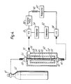
- FIG 4 an alternative embodiment of an apparatus 60 according to the present invention for removing moisture from a refrigeration unit is shown, this apparatus being particularly useful with larger refrigeration units to increase the temperature of gas, e.g. nitrogen, within the refrigeration unit.
- gas e.g. nitrogen
- the regulated gas is provided to the pipe 12 and then through a manual valve 66 which replaces the regulator 16 of Figures 1 and 3.
- the manual valve 66 may be opened, partially openeded or shut by turning a handle 68 to the appropriate position.
- a regulated check valve 70 is connected to the heating pipe 46.
- the check valve 70 is directed to only allow gas to flow into the heating pipe 46 and is coupled to the high pressure side valve 36 of the refrigeration unit. With this arrangement, gas within the refrigeration unit is fed back into the apparatus 60 and again heated. Thus, the gas may flow through the heating pipe 46 much faster in as much as it need not be heated to the maximum temperature prior to entering the refrigeration unit. Once that gas passes through the compressor 32 and the condensor 34, it has been heated due to the compression. Then, when a part of the gas is returned to the apparatus 60 through the check valve 70, it may be heated more quickly to the desired temperature.
- the size of the check valve 70 should be selected relative to the size of the tubing 40 so that approximately one-half of the gas into the high pressure valve 36 goes through the check valve 70.
Landscapes
- Engineering & Computer Science (AREA)
- Physics & Mathematics (AREA)
- Mechanical Engineering (AREA)
- Thermal Sciences (AREA)
- General Engineering & Computer Science (AREA)
- Devices That Are Associated With Refrigeration Equipment (AREA)
- Drying Of Gases (AREA)
Applications Claiming Priority (2)
| Application Number | Priority Date | Filing Date | Title |
|---|---|---|---|
| US792219 | 1985-10-28 | ||
| US06/792,219 US4683724A (en) | 1985-10-28 | 1985-10-28 | Refrigeration moisture eliminating device and method |
Publications (2)
| Publication Number | Publication Date |
|---|---|
| EP0225028A2 true EP0225028A2 (fr) | 1987-06-10 |
| EP0225028A3 EP0225028A3 (fr) | 1988-10-19 |
Family
ID=25156166
Family Applications (1)
| Application Number | Title | Priority Date | Filing Date |
|---|---|---|---|
| EP86308162A Withdrawn EP0225028A3 (fr) | 1985-10-28 | 1986-10-21 | Dispositif et procédé pour l'évacuation de l'humidité de groupes frigorifiques |
Country Status (2)
| Country | Link |
|---|---|
| US (1) | US4683724A (fr) |
| EP (1) | EP0225028A3 (fr) |
Families Citing this family (5)
| Publication number | Priority date | Publication date | Assignee | Title |
|---|---|---|---|---|
| DE4212367C2 (de) * | 1991-04-15 | 2000-08-03 | Denso Corp | Vorrichtung zur Entfernung von Wasser in einem Kühlsystem |
| US5311750A (en) * | 1992-12-17 | 1994-05-17 | Stark John P | Oil collector unit |
| CN101529170B (zh) * | 2006-10-31 | 2014-09-10 | 开利公司 | Co2制冷系统中的制冷剂释放检测 |
| CN116465107A (zh) | 2015-06-30 | 2023-07-21 | 开利公司 | 制冷系统及其净化方法 |
| CN113513865B (zh) * | 2021-06-30 | 2022-12-06 | 南京天加环境科技有限公司 | 一种冷媒自动充注多联机系统及其控制方法 |
Family Cites Families (6)
| Publication number | Priority date | Publication date | Assignee | Title |
|---|---|---|---|---|
| US3357197A (en) * | 1966-06-03 | 1967-12-12 | John L Massengale | Process and apparatus for purging refrigeration system |
| US3710585A (en) * | 1971-04-07 | 1973-01-16 | Borg Warner | Method and apparatus for removing moisture from a refrigeration system |
| US3699781A (en) * | 1971-08-27 | 1972-10-24 | Pennwalt Corp | Refrigerant recovery system |
| US4110998A (en) * | 1977-05-27 | 1978-09-05 | Charles Owen | Apparatus for detecting and removing contaminants from a refrigeration system |
| US4129997A (en) * | 1977-08-12 | 1978-12-19 | Kunkle Robert J | Permanent refrigerant dehydrator |
| US4304102A (en) * | 1980-04-28 | 1981-12-08 | Carrier Corporation | Refrigeration purging system |
-
1985
- 1985-10-28 US US06/792,219 patent/US4683724A/en not_active Expired - Fee Related
-
1986
- 1986-10-21 EP EP86308162A patent/EP0225028A3/fr not_active Withdrawn
Also Published As
| Publication number | Publication date |
|---|---|
| EP0225028A3 (fr) | 1988-10-19 |
| US4683724A (en) | 1987-08-04 |
Similar Documents
| Publication | Publication Date | Title |
|---|---|---|
| US5875638A (en) | Refrigerant recovery system | |
| CN110177983B (zh) | 具有切断阀的制冷装置 | |
| US5050394A (en) | Controllable variable speed heat pump for combined water heating and space cooling | |
| US6658875B2 (en) | Method and apparatus for temperature control in a refrigeration device | |
| CA1335944C (fr) | Procede et appareil de verification d'etancheite pour circuits de refrigerant | |
| WO2004084276A2 (fr) | Appareil et procede pour le controle de la temperature d'un dispositif electronique | |
| US6260378B1 (en) | Refrigerant purge system | |
| US2690649A (en) | Control for heat pump and water heater | |
| JPS5878050A (ja) | 熱ポンプ回路 | |
| US4683724A (en) | Refrigeration moisture eliminating device and method | |
| KR920010222A (ko) | 선택적으로 냉매 회수운전을 행하는 공기조화기 | |
| US3066497A (en) | Reversible refrigeration system | |
| US20070033955A1 (en) | Electrically controlled defrost and expansion valve apparatus | |
| US5367885A (en) | Chiller pressurization system | |
| US3503221A (en) | Dehydration,cleaning and sterilization method and apparatus | |
| JPS58179764A (ja) | ヒ−トポンプ温水機 | |
| JPH07305903A (ja) | 冷凍装置の制御装置 | |
| US5551247A (en) | Refrigerant handling system and method especially for flammable and potentially flammable refrigerants | |
| JPS6256415B2 (fr) | ||
| GB2125159A (en) | Dehumidifier | |
| JP2512161B2 (ja) | 冷暖房装置 | |
| JPH01111153A (ja) | 空気調和機の制御装置 | |
| CA1048802A (fr) | Recuperateur de chaleur | |
| CA1087707A (fr) | Appareil regulateur de charge de refrigerant | |
| JP2680326B2 (ja) | 冷暖房機 |
Legal Events
| Date | Code | Title | Description |
|---|---|---|---|
| PUAI | Public reference made under article 153(3) epc to a published international application that has entered the european phase |
Free format text: ORIGINAL CODE: 0009012 |
|
| AK | Designated contracting states |
Kind code of ref document: A2 Designated state(s): AT BE CH DE ES FR GB IT LI NL SE |
|
| PUAL | Search report despatched |
Free format text: ORIGINAL CODE: 0009013 |
|
| RHK1 | Main classification (correction) |
Ipc: F25B 43/00 |
|
| AK | Designated contracting states |
Kind code of ref document: A3 Designated state(s): AT BE CH DE ES FR GB IT LI NL SE |
|
| STAA | Information on the status of an ep patent application or granted ep patent |
Free format text: STATUS: THE APPLICATION IS DEEMED TO BE WITHDRAWN |
|
| 18D | Application deemed to be withdrawn |
Effective date: 19881101 |
|
| RIN1 | Information on inventor provided before grant (corrected) |
Inventor name: VERGEL, JORGE?§CHEM SPRAY INC |