EP0225082A2 - Trépan de forage rotatif - Google Patents
Trépan de forage rotatif Download PDFInfo
- Publication number
- EP0225082A2 EP0225082A2 EP86308791A EP86308791A EP0225082A2 EP 0225082 A2 EP0225082 A2 EP 0225082A2 EP 86308791 A EP86308791 A EP 86308791A EP 86308791 A EP86308791 A EP 86308791A EP 0225082 A2 EP0225082 A2 EP 0225082A2
- Authority
- EP
- European Patent Office
- Prior art keywords
- opening
- formation
- bit
- drill bit
- drilling fluid
- Prior art date
- Legal status (The legal status is an assumption and is not a legal conclusion. Google has not performed a legal analysis and makes no representation as to the accuracy of the status listed.)
- Withdrawn
Links
Images





Classifications
-
- E—FIXED CONSTRUCTIONS
- E21—EARTH OR ROCK DRILLING; MINING
- E21B—EARTH OR ROCK DRILLING; OBTAINING OIL, GAS, WATER, SOLUBLE OR MELTABLE MATERIALS OR A SLURRY OF MINERALS FROM WELLS
- E21B10/00—Drill bits
- E21B10/60—Drill bits characterised by conduits or nozzles for drilling fluids
- E21B10/61—Drill bits characterised by conduits or nozzles for drilling fluids characterised by the nozzle structure
-
- E—FIXED CONSTRUCTIONS
- E21—EARTH OR ROCK DRILLING; MINING
- E21B—EARTH OR ROCK DRILLING; OBTAINING OIL, GAS, WATER, SOLUBLE OR MELTABLE MATERIALS OR A SLURRY OF MINERALS FROM WELLS
- E21B10/00—Drill bits
- E21B10/60—Drill bits characterised by conduits or nozzles for drilling fluids
- E21B10/602—Drill bits characterised by conduits or nozzles for drilling fluids the bit being a rotary drag type bit with blades
Definitions
- the invention relates to rotary drill bits for use in drilling deep holes in subsurface formations.
- the invention relates to drill bits of the kind comprising a bit body having a leading face and a gauge region, a plurality of blades each extending across the leading face of the bit body away from the axis of rotation thereof and towards the gauge region, each blade having an outer surface which, in use, faces the surface of the formation being drilled and a front surface facing in the direction of normal forward rotation of the bit, a plurality of cutting elements mounted along each blade, an exit channel in the gauge region of the bit body between each pair of adjacent blades, and a passage in the bit body for supplying drilling fluid to a plurality of openings in the leading face of the bit.
- the aforesaid openings for drilling fluid are located on the bit body between adjacent blades and are so located as to promote a flow of drilling fluid across the front surfaces of the blades and the cutting elements mounted thereon.
- the flow of drilling fluid cleans and cools the cutters and carries cuttings outwardly and upwardly through the exit channels in the gauge region.
- Drill bits of the above-mentioned kind are normally substantially symmetrical and, conventionally, the openings are normally arranged in substantially the same manner in each of the areas of the bit between two adjacent blades. This is because it has been considered desirable for the flow over the front surface of each blade to be substantially the same to provide optimum cleaning and cooling of the cutters on the blade.
- the present invention depends on the realisation that, contrary to what has previously been believed in relation to bits of this type, the impingement of the jet of drilling fluid on the surface of the formation itself plays an important part in the effective operation of the bit. It has previously been considered that the required cooling and cleaning objectives would be met by the emergence of the jet of drilling fluid from the openings causing a general area of turbulent flow within the whole space between adjacent blades.
- the present invention depends on the realisation that the direct impingement of a high velocity turbulent jet of drilling fluid on the surface of the formation itself performs a highly important function.
- the impingement of the jet on the formation at high velocity, particularly in a region on the front side of an advancing blade, causes effective cooling of the formation and this leads to less heating of the cutters which then act on the formation. This is believed to be more effective than the conventional method whereby the primary cooling purpose of the drilling fluid is to cool the cutters themselves.
- the impingement of the high velocity turbulent jets on the formation serves to lift cuttings created by the cutters and separate them from the surface of the formation so that they become entrained in the flow of drilling fluid.
- the present invention sets out to provide a construction of drill bit which takes advantage of the above-mentioned advantageous effects of jet impingement on the formation.
- a drill bit comprising a bit body having a leading face and a gauge region, a plurality of blades each extending across the leading face of the bit body away from the axis of rotation thereof and towards the gauge region, the number of blades being from two to four inclusive, each blade having an outer surface which, in use, faces the surface of the formation being drilled and a front surface facing in the direction of normal forward rotation of the bit, a plurality of cutting elements mounted along each blade, an exit channel in the gauge region of the bit body between each pair of adjacent blades, a plurality of openings in the leading face of the bit, each opening having a central axis which also forms the central axis of the jet of drilling fluid emerging therefrom, at least one opening being located between each pair of adjacent blades, and a passage in the bit body for supplying drilling fluid to said openings, said openings being so located that, in use, the central axes of openings between different pairs of adjacent blades intersect the surface of the formation being drilled at different distances from
- a jet of fluid emerges at high velocity from each opening and impinges on the formation in front of a portion of the associated advancing blade.
- the length of the portion of the blade affected by the jet is determined by the spread of the jet after leaving the opening.
- the different dispositions of the openings means that each jet sweeps a different annular area of the surface of the formation as the bit rotates, and preferably the dispositions of the openings are such that the jets from the openings between them sweep substantially the whole area of the surface of the formation between the axis of rotation of the bit and the gauge region.
- central axes of the openings between different pairs of adjacent blades are inclined at different angles to the axis of rotation of the bit.
- each opening for drilling fluid is substantially parallel to the front surface of the adjacent blade.
- the angular orientation of each opening is such that the central axis thereof is substantially at right angles to the surface of the formation opposite the opening (i.e. is less than 30° and preferably less than 15° to the normal) so that the jet of drilling fluid impinges substantially normally on to the surface of the formation.
- each said opening may be provided in a nozzle which is separately formed from the bit body and is mounted therein.
- the nozzle may be removably secured within a socket in the bit body.
- each opening is such that its distance from the point where the jet of drilling fluid impinges on the formation is less than five times the diameter of the opening.
- said distance is less than four times the opening diameter and even more preferably less than three times said diameter.
- a drill bit of the basic kind to which the invention relates may be designed to provide a substantial clearance in front of the blades carrying the cutting elements and hence a large flow path for the escape, through the associated exit channel, of cuttings produced by the cutting elements. It is believed that this substantial clearance is one of the reasons for the high penetration rates which drill bits of this kind may achieve in certain types of formation. It is therefore undesirable to achieve the desirable closeness of the openings to the surface of the formation by reducing the clearance between the surface of the bit body and the cutting elements on the forward side of each blade.
- the required optimum distance of the openings from the surface of the formation is achieved by providing each opening at the extremity of a structure which projects from the main surface of the bit body on the forward side of each blade so as to bring the opening nearer the formation.
- the surface of the bit body may be formed with a projecting boss the opening being formed in the outer extremity thereof.
- the nozzle may be an extended nozzle one end of which projects from the surface of the bit body and is formed with the opening and the opposite end of which is secured in a socket in the bit body.
- the extended nozzle is preferably formed from an erosion resistant material such as tungsten carbide.
- the bit body 10 of a rotary drill bit for use in drilling deep holes in subsurface formations.
- the bit body 10 may be formed from steel and has a leading face 11 and a gauge region 12.
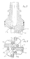
- the leading face 11 of the bit body is integrally formed with blades 13. As best seen in Figure 2, there are provided four such blades spaced substantially equally around the central axis of rotation of the bit. Each blade has an outer surface 14 which, in use of the bit, faces the surface of the formation being drilled, and a front surface 15 facing in the direction of normal forward rotation of the bit.
- a plurality of cutting elements 8 are mounted on each blade 13 along the junction between the outer surface 14 and the front surface 15.
- Each cutting element is in the form of a circular preform comprising a front hard facing layer of polycrystalline diamond or other superhard material bonded to a less hard backing layer, such as tungsten carbide.
- Each cutting element is bonded to a post 7, for example of tungsten carbide, received in a socket in the blade 13. The construction of such cutting elements is well known and will not be described in detail.
- the rear surface of each blade 13 is chamfered as indicated at 9.
- gauge region 12 of the bit is formed with abrasion elements 16 which may, for example, comprise tungsten carbide studs impregnated with natural diamond particles and received in sockets in the gauge portion.
- the gauge portion comprises four axially extending kickers or wear pads 17 in which the abrasion elements are mounted, exit channels 18 being disposed between the kickers 17.
- each blade 13 On the forward side of each blade 13 a nozzle is mounted in a socket in the bit body, the four nozzles being indicated at 19 a , 19 c , 19 b , and 19 d respectively.
- Each nozzle communicates through a passage with a central passage 6 in the bit body.
- drilling fluid supplied under pressure through the central passage 6 emerges from the nozzles 19 a - 19 d for the purpose of cleaning and cooling the cutting elements as well as cooling the formation.
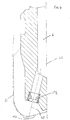
- Figures 3 to 6 are half-sections of the bit body through each of the four nozzles 19 a - 19 d and showing the preferred position and orientation of each nozzle.
- the central axis of each nozzle is indicated at 20.
- the axis 20 also represents the central axis of the jet of drilling fluid which emerges under high pressure from the nozzle.
- the surface of the formation being drilled by the drill bit is indicated diagrammatically at 21.
- each nozzle lies in a plane which is substantially parallel to the front surface 15 of the associated blade. It will be seen from Figures 3 to 6 that the central axes of the four nozzles are inclined at different angles to the central axis of rotation 22 of the bit and the effect of this angular orientation, together with the location of the nozzles, is that the jet of drilling fluid from each nozzle impinges on a different portion of the surface 21, the portion of the surface on which the jet impinges in each case being indicated at 23.
- the diameter of the area of influence of each jet is greater than the diameter of the nozzle opening, and the orientation of the nozzles is such that the four areas 23 of the formation on which the jets impinge between them cover substantially the whole of the formation from the gauge region to a position close to the central axis 22 of the drill bit.
- the effect of this is that the four jets between them will, as the bit rotates, sweep out a total area extending over substantially the whole of the formation at the bottom of the hole.
- substantially all the surface of the formation is subjected to direct impingement by a high pressure turbulent jet of drilling fluid with all the advantages this gives, as previously referred to.
- each nozzle is arranged as nearly as possible at right angles to the surface of the formation. It will be seen that in the case of the nozzles shown in Figure 5 the central axis is very close to being at right angles to the surface of the formation whereas, due to limitations imposed by the structure of the bit body, in the case of the nozzles shown in Figures 3, 4 and 6 the central axis is at a greater angle to the normal. Desirably the angle to the normal is not more than 30° and preferably is less than 15°.
- the distance of the opening in each nozzle from the formation should not be greater than five times the diameter of the opening, preferably not more than four times the diameter, and more preferably not more than three times the diameter. If the nozzle is received in a socket in the bit body, as shown in Figures 3 to 6, the location of the surface 24 of the bit body in relation to the formation 21 will be determined by the required position of the nozzle. In other words, if it were wished to move the nozzles 19 closer to the formation 21 it would be necessary to bring the surface 24 closer to the formation to accommodate the nozzles.
- each nozzle may be brought closer to the formation without reducing the overall clearance by locating each nozzle in a boss which is integral with the surface 24 of the bit body but which projects towards the formation.
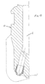
- each nozzle may be in the form of an extended element 25 one end of which is secured within the socket in the surface 24 of the bit body and the other end of which projects away from the surface 24 towards the surface of the formation.
- Such projecting portion of the extended nozzle is preferably formed from tungsten carbide or similar erosion-resistant material.
- the leading face 111 of the bit body is again integrally formed with four blades 113 in generally similar fashion to the arrangement of Figures 1 and 2.
- an abrasion element 126 which may, for example, comprise a tungsten carbide stud impregnated with natural diamond particles and received in a socket in the blade.
- each blade 113 On the forward side of each blade 113 a nozzle is mounted in a socket in the bit body, four nozzles being indicated at 119 a , 119 b , 119 c and 119 d respectively.
- the central axes of these four nozzles are inclined at different angles to the central axis of rotation of the bit so that the jet of drilling fluid from each nozzle impinges on a different portion of the surface of the formation.
- a further, fifth nozzle 127 which is located on the forward side of the same blade as the nozzle 119 c but is located close to the central axis of the bit and is directed in a direction generally parallel to that axis.
- the object of the further nozzle 127 is to provide more effective cleaning and cooling of the cutting elements, and cooling of the formation, in the vicinity of the central axis of the bit.
- the invention is applicable to drill bits having two, three or four blades, and Figure 9 shows an arrangement where the leading face of the bit body is integrally formed with only three blades 213 spaced equally around the central axis of rotation of the bit.
- Each blade has an outer surface 214 which faces the surface of the formation being drilled, and a front surface 215 facing in the direction of normal forward rotation of the bit.
- a plurality of cutting elements 208 are mounted along each blade 213, each cutting element being in the form of a circular polycrystalline diamond preform.
- each blade 213 On the forward side of each blade 213 a nozzle is mounted in a socket in the bit body, the three nozzles being indicated at 219 a , 219 b and 219 c respectively.
- the central axes of the three nozzles are inclined at different angles to the central axis of rotation of the bit so that the jets of drilling fluid from the nozzles impinge on different portions of the surface of the formation being drilled.
Landscapes
- Engineering & Computer Science (AREA)
- Life Sciences & Earth Sciences (AREA)
- Geology (AREA)
- Mining & Mineral Resources (AREA)
- Mechanical Engineering (AREA)
- Physics & Mathematics (AREA)
- Environmental & Geological Engineering (AREA)
- Fluid Mechanics (AREA)
- General Life Sciences & Earth Sciences (AREA)
- Geochemistry & Mineralogy (AREA)
- Earth Drilling (AREA)
Applications Claiming Priority (2)
| Application Number | Priority Date | Filing Date | Title |
|---|---|---|---|
| GB8528299 | 1985-11-16 | ||
| GB858528299A GB8528299D0 (en) | 1985-11-16 | 1985-11-16 | Rotary drill bits |
Publications (2)
| Publication Number | Publication Date |
|---|---|
| EP0225082A2 true EP0225082A2 (fr) | 1987-06-10 |
| EP0225082A3 EP0225082A3 (fr) | 1988-07-27 |
Family
ID=10588345
Family Applications (1)
| Application Number | Title | Priority Date | Filing Date |
|---|---|---|---|
| EP86308791A Withdrawn EP0225082A3 (fr) | 1985-11-16 | 1986-11-12 | Trépan de forage rotatif |
Country Status (2)
| Country | Link |
|---|---|
| EP (1) | EP0225082A3 (fr) |
| GB (2) | GB8528299D0 (fr) |
Cited By (9)
| Publication number | Priority date | Publication date | Assignee | Title |
|---|---|---|---|---|
| EP0370717A1 (fr) * | 1988-11-21 | 1990-05-30 | Smith International, Inc. | Trépan racleur diamanté pour formations molles |
| EP0556648A1 (fr) * | 1992-02-18 | 1993-08-25 | Baker Hughes Incorporated | Trépan avec lames à inclinaisons positives et négatives |
| EP0624707A3 (fr) * | 1993-05-10 | 1995-05-10 | Smith International | Arrangement de buses pour trépan racleur. |
| US5794725A (en) * | 1996-04-12 | 1998-08-18 | Baker Hughes Incorporated | Drill bits with enhanced hydraulic flow characteristics |
| US6302223B1 (en) | 1999-10-06 | 2001-10-16 | Baker Hughes Incorporated | Rotary drag bit with enhanced hydraulic and stabilization characteristics |
| WO2012051648A1 (fr) * | 2010-10-19 | 2012-04-26 | Drilling Tools Australia Pty Ltd | Foret |
| CN112696155A (zh) * | 2019-10-22 | 2021-04-23 | 西南石油大学 | 一种具有后排齿水孔的pdc钻头 |
| CN113404439A (zh) * | 2021-06-11 | 2021-09-17 | 东北石油大学 | 一种粒子冲击钻头 |
| CN117046890A (zh) * | 2023-09-11 | 2023-11-14 | 滨州市生态环境服务中心 | 一种用于磷污染土壤原位修复的方法 |
Families Citing this family (1)
| Publication number | Priority date | Publication date | Assignee | Title |
|---|---|---|---|---|
| FR2756002B1 (fr) * | 1996-11-20 | 1999-04-02 | Total Sa | Outil de forage a lames avec taillants de reserve et canaux d'evacuation des deblais generes par les taillants |
Family Cites Families (8)
| Publication number | Priority date | Publication date | Assignee | Title |
|---|---|---|---|---|
| US3112803A (en) * | 1962-01-02 | 1963-12-03 | Jersey Prod Res Co | Diamond drill bit |
| US4098363A (en) * | 1977-04-25 | 1978-07-04 | Christensen, Inc. | Diamond drilling bit for soft and medium hard formations |
| US4341273A (en) * | 1980-07-04 | 1982-07-27 | Shell Oil Company | Rotary bit with jet nozzles |
| US4499958A (en) * | 1983-04-29 | 1985-02-19 | Strata Bit Corporation | Drag blade bit with diamond cutting elements |
| GB2148978B (en) * | 1983-10-29 | 1987-01-07 | Nl Petroleum Prod | Improvements in or relating to rotary drill bits |
| ATE42384T1 (de) * | 1983-11-08 | 1989-05-15 | Flow Ind Inc | Leckfreie schneidduesen-einheit fuer fluessigkeiten hohen druckes und hoher geschwindigkeit. |
| FR2566833B1 (fr) * | 1984-06-27 | 1986-11-14 | Inst Francais Du Petrole | Methode et perfectionnement aux outils de forage comportant des passages d'eau permettant une grande efficacite du nettoyage du front de taille |
| GB8418481D0 (en) * | 1984-07-19 | 1984-08-22 | Nl Petroleum Prod | Rotary drill bits |
-
1985
- 1985-11-16 GB GB858528299A patent/GB8528299D0/en active Pending
-
1986
- 1986-11-12 EP EP86308791A patent/EP0225082A3/fr not_active Withdrawn
- 1986-11-12 GB GB08627050A patent/GB2183693A/en not_active Withdrawn
Cited By (13)
| Publication number | Priority date | Publication date | Assignee | Title |
|---|---|---|---|---|
| EP0370717A1 (fr) * | 1988-11-21 | 1990-05-30 | Smith International, Inc. | Trépan racleur diamanté pour formations molles |
| EP0556648A1 (fr) * | 1992-02-18 | 1993-08-25 | Baker Hughes Incorporated | Trépan avec lames à inclinaisons positives et négatives |
| EP0624707A3 (fr) * | 1993-05-10 | 1995-05-10 | Smith International | Arrangement de buses pour trépan racleur. |
| US5794725A (en) * | 1996-04-12 | 1998-08-18 | Baker Hughes Incorporated | Drill bits with enhanced hydraulic flow characteristics |
| US5836404A (en) * | 1996-04-12 | 1998-11-17 | Baker Hughes Incorporated | Drill bits with enhanced hydraulic flow characteristics |
| US6079507A (en) * | 1996-04-12 | 2000-06-27 | Baker Hughes Inc. | Drill bits with enhanced hydraulic flow characteristics |
| US6302223B1 (en) | 1999-10-06 | 2001-10-16 | Baker Hughes Incorporated | Rotary drag bit with enhanced hydraulic and stabilization characteristics |
| BE1014241A5 (fr) | 1999-10-06 | 2003-07-01 | Baker Hughes Inc | Trepan de forage rotatif a lames presentant des caracteristiques hydrauliques et de stabilisation ameliorees. |
| WO2012051648A1 (fr) * | 2010-10-19 | 2012-04-26 | Drilling Tools Australia Pty Ltd | Foret |
| CN112696155A (zh) * | 2019-10-22 | 2021-04-23 | 西南石油大学 | 一种具有后排齿水孔的pdc钻头 |
| CN113404439A (zh) * | 2021-06-11 | 2021-09-17 | 东北石油大学 | 一种粒子冲击钻头 |
| CN117046890A (zh) * | 2023-09-11 | 2023-11-14 | 滨州市生态环境服务中心 | 一种用于磷污染土壤原位修复的方法 |
| CN117046890B (zh) * | 2023-09-11 | 2024-02-13 | 滨州市生态环境服务中心 | 一种用于磷污染土壤原位修复的方法 |
Also Published As
| Publication number | Publication date |
|---|---|
| EP0225082A3 (fr) | 1988-07-27 |
| GB2183693A (en) | 1987-06-10 |
| GB8528299D0 (en) | 1985-12-18 |
| GB8627050D0 (en) | 1986-12-10 |
Similar Documents
| Publication | Publication Date | Title |
|---|---|---|
| EP0219992B1 (fr) | Trépan de forage rotatif | |
| US4718505A (en) | Rotary drill bits | |
| EP0418706B1 (fr) | Trépan de forage pour formations dures et tendres | |
| US5531281A (en) | Rotary drilling tools | |
| US4823892A (en) | Rotary drill bits | |
| US5732784A (en) | Cutting means for drag drill bits | |
| US4538691A (en) | Rotary drill bit | |
| US6450270B1 (en) | Rotary cone bit for cutting removal | |
| US5103922A (en) | Fishtail expendable diamond drag bit | |
| US4640374A (en) | Rotary drill bit | |
| CA1164856A (fr) | Trepan de forage | |
| US4848491A (en) | Rotary drill bits | |
| US4852671A (en) | Diamond cutting element | |
| US5553681A (en) | Rotary cone drill bit with angled ramps | |
| CA2378534C (fr) | Trepan a molettes avec accessoire attachable pour ameliorer le nettoyage des cones | |
| US4794994A (en) | Drag drill bit having improved flow of drilling fluid | |
| US4907662A (en) | Rotary drill bit having improved mounting means for multiple cutting elements | |
| EP0295045A2 (fr) | Trépan racleur rotatif avec des buses de nettoyage | |
| EP0496417A1 (fr) | Procédé et appareil pour l'orientation du fluide de forage à l'arête coupante des éléments de coupe | |
| US5699868A (en) | Rotary drill bits having nozzles to enhance recirculation | |
| US5417296A (en) | Rotary drill bits | |
| EP0145422A2 (fr) | Trépan de forage rotatif | |
| EP0898045A2 (fr) | Structure de coupe pour trépan de forage rotatif avec canaux pour fluide de forage | |
| EP0192016B1 (fr) | Trépan rotatif | |
| GB2183693A (en) | Improvements in or relating to rotary drill bits |
Legal Events
| Date | Code | Title | Description |
|---|---|---|---|
| PUAI | Public reference made under article 153(3) epc to a published international application that has entered the european phase |
Free format text: ORIGINAL CODE: 0009012 |
|
| AK | Designated contracting states |
Kind code of ref document: A2 Designated state(s): BE CH DE FR LI NL SE |
|
| PUAL | Search report despatched |
Free format text: ORIGINAL CODE: 0009013 |
|
| AK | Designated contracting states |
Kind code of ref document: A3 Designated state(s): BE CH DE FR LI NL SE |
|
| STAA | Information on the status of an ep patent application or granted ep patent |
Free format text: STATUS: THE APPLICATION IS DEEMED TO BE WITHDRAWN |
|
| 18D | Application deemed to be withdrawn |
Effective date: 19890128 |
|
| RIN1 | Information on inventor provided before grant (corrected) |
Inventor name: FULLER, JOHN Inventor name: COMBER, PETER JOHN |