EP0225092A2 - Configuration de circuit pour la protection d'un CRT et des circuits associés contre les dommages dûs à la formation d'arc - Google Patents
Configuration de circuit pour la protection d'un CRT et des circuits associés contre les dommages dûs à la formation d'arc Download PDFInfo
- Publication number
- EP0225092A2 EP0225092A2 EP86308911A EP86308911A EP0225092A2 EP 0225092 A2 EP0225092 A2 EP 0225092A2 EP 86308911 A EP86308911 A EP 86308911A EP 86308911 A EP86308911 A EP 86308911A EP 0225092 A2 EP0225092 A2 EP 0225092A2
- Authority
- EP
- European Patent Office
- Prior art keywords
- crt
- scr
- grid
- cathode
- anode
- Prior art date
- Legal status (The legal status is an assumption and is not a legal conclusion. Google has not performed a legal analysis and makes no representation as to the accuracy of the status listed.)
- Withdrawn
Links
Images
Classifications
-
- H—ELECTRICITY
- H04—ELECTRIC COMMUNICATION TECHNIQUE
- H04N—PICTORIAL COMMUNICATION, e.g. TELEVISION
- H04N3/00—Scanning details of television systems; Combination thereof with generation of supply voltages
- H04N3/10—Scanning details of television systems; Combination thereof with generation of supply voltages by means not exclusively optical-mechanical
- H04N3/16—Scanning details of television systems; Combination thereof with generation of supply voltages by means not exclusively optical-mechanical by deflecting electron beam in cathode-ray tube, e.g. scanning corrections
- H04N3/20—Prevention of damage to cathode-ray tubes in the event of failure of scanning
Definitions
- This invention relates to a circuit arrangement for protecting a cathode-ray tube (CRT) and associated circuitry from damage due to arcing between the electrodes of the CRT.
- CRT cathode-ray tube
- a conventional cathode-ray tube normally comprises, between the cathode and the anode, three grids that are commonly known as G1, G2 and G3. Either the cathode or the grid G1 is effectively grounded, the CRT's video amplifier being connected to whichever of these two electrodes is not grounded, and the potential difference between the cathode and the grid G1 determines the beam current of the CRT.
- the grid G2 is maintained at a potential of about 200 to 800 volts, which is adjusted to establish a beam current cut-off point with a given G1 to cathode voltage.
- the focus grid G3 is normally maintained at a potential of about 6 kv, whereas the anode is maintained at a potential of about 25 kv.
- This capacitance is usually a capacitance associated with the anode that stores a substantial amount of energy.
- This capacitance may be the dag capacitance due to the CRT's external conductive coating, or it may be a filter capacitance in the power supply.
- Every CRT has the potential to arc via high voltage breakdown between the internal elements of the CRT. This breakdown is usually initiated by sharp burrs on the gun elements or loose particles within the CRT.
- the arc usually starts between G3 and the anode, where the highest potential difference exists. Normally, the arc then propagates down the CRT to G2.
- the G2 circuitry is usually of quite high impedance. Therefore, when the arc reaches G2 the voltage level of G2 goes very high, turning the beam on very hard. The arc can then propagate to G1 and the cathode. This may result in destruction of the video amplifier or the cathode itself.
- the energy dissipated in the arc is usually quite high because of the charge stored on the capacitance associated with the anode.
- the currents generated by the arc have very short rise times, and the voltage rise times of elements connected to a high impedance are very high also (normally greater than 500 kv/ ⁇ s).
- a spark gap comprises two spaced apart electrodes. When a voltage exceeding a threshold voltage is applied to the electrodes of the spark gap, an arc will occur in the spark gap.
- the spark gap is connected between a selected electrode, other than the anode, and a reference potential level, e.g. ground. When an arc forms, the voltage on the selected electrode of the CRT increases, increasing the voltage across the spark gap.
- the spark gap fires and establishes a low resistance path between the selected electrode and ground, and the energy stored in the capacitance associated with the anode is shunted to ground.
- ionization of the gas in the spark gap path does not take place instantaneously, and there might be a significant delay between onset of a high voltage condition and firing of the spark gap.
- the length of the delay depends upon the magnitude of the potential difference, and the gap voltage can exceed the rated firing voltage of the spark gap for a short period of time without the spark gap's firing. This time may be sufficient for the arc to cascade down the CRT from one electrode to the next, and to cause large, fast voltage transitions to occur on these electrodes, possibly damaging the electrodes and circuitry connected to the electrodes.
- a silicon controlled rectifier is a semiconductor device having an anode, a cathode and a gate. In its normal mode of operation, the SCR is turned on (rendered conductive) by applying a small current to its gate, and the SCR remains conductive so long as the current flowing from its anode to its cathode remains above a holding value. An SCR will also be turned on if the potential difference between its anode and cathodes is increased at an excessive rate. For example, the Motorola 2N6241 has a dv/dt rating of 10 v/ ⁇ s (typical).
- the dv/dt rating of an SCR is a warning to the circuit designer to ensure that the SCR will not be exposed to potential differences changing at a rate greater than the quoted rating, since otherwise the SCR will be turned on otherwise than in response to a signal applied to its gate.
- a silicon controlled rectifier is connected between a selected electrode of a CRT and a reference potential level that is negative relative to the selected CRT electrode.
- the SCR remains non-conductive so long as the voltage between the selected electrode and the reference potential level remains below the breakdown voltage of the SCR and the SCR's dv/dt rating is not exceeded. If the voltage between the electrode and the reference potential level increases at a rate that exceeds the threshold rate for the SCR, the SCR turns on and shorts the selected electrode to the reference potential level.
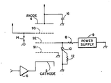
- the CRT shown in Fig. 1 comprises a cathode 2, grids G1, G2 and G3, and an anode 4.
- the grid G1 is grounded.
- the cathode 2 is maintained at a DC potential of about +60 volts, and receives a beam intensity modulation signal by way of a video amplifier 6.
- the grid G2 is connected through a resistor 8 to a power supply 9 having a potential of 200 to 800 volts, and is connected to ground through an SCR 10.
- the power supply 9 is of the kind that shuts down automatically when its load is short-circuited.
- the power supply 6 may be designed so that the current that it can supply through the resistor 8 is smaller than the holding current of the SCR.
- a resistor 12 is connected between the gate and the cathode of the SCR.
- the focus grid G3 is connected to a power supply having a voltage potential of about 6 kv, whereas the anode 4 is connected to a power supply having a voltage potential of about 25 kv.
- a dag or filter capacitance 16 of about 2000 pF is connected between the anode 4 and the ground.
- a spark gap 14 is connected between the focus electrode and ground.
- the power supply must be turned on again in order to restore the voltage of the grid G2 to its normal operating value. If the output current of the power supply 9 is less than the holding current of the SCR, the SCR turns off when the arc is extinguished without the power supply's turning off, and therefore when the arc is extinguished the circuit is automatically reset without there being any need for operator intervention. In either case, shorting the grid G2 to ground results in the potential difference between the grid G2 and the grid G1 being made quite small, so that propagation of the arc to the grid G1 and the cathode 2 is inhibited. This protects both the cathode 2 and the video amplifier 6.
Landscapes
- Engineering & Computer Science (AREA)
- Multimedia (AREA)
- Signal Processing (AREA)
- Particle Accelerators (AREA)
- Protection Of Static Devices (AREA)
- Power Conversion In General (AREA)
- Measurement Of Current Or Voltage (AREA)
- Emergency Protection Circuit Devices (AREA)
Applications Claiming Priority (2)
| Application Number | Priority Date | Filing Date | Title |
|---|---|---|---|
| US798658 | 1985-11-15 | ||
| US06/798,658 US4706154A (en) | 1985-11-15 | 1985-11-15 | Circuit arrangement for protecting a CRT and associated circuitry from damage due to arcing |
Publications (2)
| Publication Number | Publication Date |
|---|---|
| EP0225092A2 true EP0225092A2 (fr) | 1987-06-10 |
| EP0225092A3 EP0225092A3 (fr) | 1988-09-28 |
Family
ID=25173955
Family Applications (1)
| Application Number | Title | Priority Date | Filing Date |
|---|---|---|---|
| EP86308911A Withdrawn EP0225092A3 (fr) | 1985-11-15 | 1986-11-14 | Configuration de circuit pour la protection d'un CRT et des circuits associés contre les dommages dûs à la formation d'arc |
Country Status (3)
| Country | Link |
|---|---|
| US (1) | US4706154A (fr) |
| EP (1) | EP0225092A3 (fr) |
| JP (1) | JPS62152323A (fr) |
Families Citing this family (1)
| Publication number | Priority date | Publication date | Assignee | Title |
|---|---|---|---|---|
| JPS62122474A (ja) * | 1985-11-22 | 1987-06-03 | Reader Denshi Kk | 輝度制御装置 |
Family Cites Families (5)
| Publication number | Priority date | Publication date | Assignee | Title |
|---|---|---|---|---|
| JPS4318836Y1 (fr) * | 1965-09-13 | 1968-08-05 | ||
| US3668465A (en) * | 1971-02-16 | 1972-06-06 | Seaco Computer Display Inc | Surge voltage protection for cathode ray tube drivers |
| US3965393A (en) * | 1971-04-21 | 1976-06-22 | Admiral Corporation | Television X-radiation protection device and circuit |
| US3934175A (en) * | 1973-12-03 | 1976-01-20 | General Semiconductor Industries, Inc. | Power surge protection system |
| DE3240708C2 (de) * | 1982-11-04 | 1986-12-18 | Blaupunkt-Werke Gmbh, 3200 Hildesheim | Strahlstromschutzschaltung für die Bildröhre eines Fernsehempfängers |
-
1985
- 1985-11-15 US US06/798,658 patent/US4706154A/en not_active Expired - Fee Related
-
1986
- 1986-11-13 JP JP61270816A patent/JPS62152323A/ja active Pending
- 1986-11-14 EP EP86308911A patent/EP0225092A3/fr not_active Withdrawn
Also Published As
| Publication number | Publication date |
|---|---|
| EP0225092A3 (fr) | 1988-09-28 |
| US4706154A (en) | 1987-11-10 |
| JPS62152323A (ja) | 1987-07-07 |
Similar Documents
| Publication | Publication Date | Title |
|---|---|---|
| JP2876093B2 (ja) | 映像管用グリッドバイアス制御回路 | |
| US20090021881A1 (en) | Overvoltage protection device with improved leakage-current-interrupting capacity | |
| US4037266A (en) | Voltage surge protector | |
| US3339112A (en) | Voltage limiting protective arrangement for high voltage power circuits | |
| US4315195A (en) | High-voltage supply for power electron-beam guns | |
| EP0061838B1 (fr) | Dispositifs de protection contre les surtensions | |
| JPH04229771A (ja) | ビデオ表示装置 | |
| US4706154A (en) | Circuit arrangement for protecting a CRT and associated circuitry from damage due to arcing | |
| US4147915A (en) | Electron-beam apparatus for thermal treatment by electron bombardment | |
| US3668465A (en) | Surge voltage protection for cathode ray tube drivers | |
| US5528108A (en) | Field emission device arc-suppressor | |
| US4870529A (en) | Active arc protection circuit | |
| US3609200A (en) | Power supply | |
| US3287588A (en) | Spark gap type of surge arrestor for a d.-c. system | |
| US3786275A (en) | Circuit and method for arc protection of linear beam devices | |
| US4029997A (en) | Surge voltage arrester arrangement | |
| GB2094078A (en) | Surge voltage protection arrangements | |
| US2635208A (en) | Television circuit | |
| US3114077A (en) | Protective apparatus for high voltage electrical equipment | |
| JPH03133040A (ja) | 高電圧電子銃装置 | |
| US3309555A (en) | Spark-gap type of surge arrestor for a d.-c. system | |
| JPS5997280A (ja) | テレビ受像機のブラウン管用保護回路 | |
| CN117833031A (zh) | 一种离子发生器及其保护方法、装置和电路 | |
| US4161009A (en) | Automatic crowbar and arc quenching system | |
| JP3242766B2 (ja) | 半導体式避雷装置 |
Legal Events
| Date | Code | Title | Description |
|---|---|---|---|
| PUAI | Public reference made under article 153(3) epc to a published international application that has entered the european phase |
Free format text: ORIGINAL CODE: 0009012 |
|
| AK | Designated contracting states |
Kind code of ref document: A2 Designated state(s): DE FR GB NL |
|
| PUAL | Search report despatched |
Free format text: ORIGINAL CODE: 0009013 |
|
| AK | Designated contracting states |
Kind code of ref document: A3 Designated state(s): DE FR GB NL |
|
| STAA | Information on the status of an ep patent application or granted ep patent |
Free format text: STATUS: THE APPLICATION IS DEEMED TO BE WITHDRAWN |
|
| 18D | Application deemed to be withdrawn |
Effective date: 19890329 |
|
| RIN1 | Information on inventor provided before grant (corrected) |
Inventor name: BAUR, BRUCE K. |