EP0225207A1 - Kinematische Übertragungskette zwischen dem Steuermechanismus und den Polen eines elektrischen Lastschalters mit einem gespritzten Isoliergehäuse - Google Patents
Kinematische Übertragungskette zwischen dem Steuermechanismus und den Polen eines elektrischen Lastschalters mit einem gespritzten Isoliergehäuse Download PDFInfo
- Publication number
- EP0225207A1 EP0225207A1 EP86402269A EP86402269A EP0225207A1 EP 0225207 A1 EP0225207 A1 EP 0225207A1 EP 86402269 A EP86402269 A EP 86402269A EP 86402269 A EP86402269 A EP 86402269A EP 0225207 A1 EP0225207 A1 EP 0225207A1
- Authority
- EP
- European Patent Office
- Prior art keywords
- housing
- pole
- insulating
- cage
- circuit breaker
- Prior art date
- Legal status (The legal status is an assumption and is not a legal conclusion. Google has not performed a legal analysis and makes no representation as to the accuracy of the status listed.)
- Granted
Links
- 230000007246 mechanism Effects 0.000 title claims abstract description 23
- 230000005540 biological transmission Effects 0.000 title claims abstract description 9
- 230000008878 coupling Effects 0.000 claims abstract description 27
- 238000010168 coupling process Methods 0.000 claims abstract description 27
- 238000005859 coupling reaction Methods 0.000 claims abstract description 27
- 238000005192 partition Methods 0.000 claims abstract description 12
- 238000000605 extraction Methods 0.000 claims abstract description 8
- 238000013519 translation Methods 0.000 claims abstract description 5
- 238000004891 communication Methods 0.000 claims abstract description 3
- 239000007789 gas Substances 0.000 claims description 4
- 239000002184 metal Substances 0.000 claims description 4
- 229910052751 metal Inorganic materials 0.000 claims description 4
- 238000000926 separation method Methods 0.000 claims description 4
- 230000000007 visual effect Effects 0.000 claims description 4
- 230000000903 blocking effect Effects 0.000 claims description 3
- 230000006835 compression Effects 0.000 claims description 2
- 238000007906 compression Methods 0.000 claims description 2
- 238000000465 moulding Methods 0.000 claims description 2
- 238000012795 verification Methods 0.000 claims description 2
- 230000014759 maintenance of location Effects 0.000 claims 1
- 230000005405 multipole Effects 0.000 claims 1
- 230000000717 retained effect Effects 0.000 claims 1
- 238000011179 visual inspection Methods 0.000 abstract 1
- 230000005520 electrodynamics Effects 0.000 description 5
- 230000008033 biological extinction Effects 0.000 description 3
- 238000003780 insertion Methods 0.000 description 3
- 230000037431 insertion Effects 0.000 description 3
- 230000000694 effects Effects 0.000 description 2
- 238000004146 energy storage Methods 0.000 description 2
- 239000011810 insulating material Substances 0.000 description 2
- 238000004519 manufacturing process Methods 0.000 description 2
- RYGMFSIKBFXOCR-UHFFFAOYSA-N Copper Chemical compound [Cu] RYGMFSIKBFXOCR-UHFFFAOYSA-N 0.000 description 1
- 230000009471 action Effects 0.000 description 1
- 230000004888 barrier function Effects 0.000 description 1
- 239000004020 conductor Substances 0.000 description 1
- 229910052802 copper Inorganic materials 0.000 description 1
- 239000010949 copper Substances 0.000 description 1
- 238000006073 displacement reaction Methods 0.000 description 1
- 238000011156 evaluation Methods 0.000 description 1
- 238000010348 incorporation Methods 0.000 description 1
- 238000009434 installation Methods 0.000 description 1
- 238000012423 maintenance Methods 0.000 description 1
- 238000006386 neutralization reaction Methods 0.000 description 1
- 230000011664 signaling Effects 0.000 description 1
- 238000011144 upstream manufacturing Methods 0.000 description 1
- 238000012800 visualization Methods 0.000 description 1
Images


Classifications
-
- H—ELECTRICITY
- H01—ELECTRIC ELEMENTS
- H01H—ELECTRIC SWITCHES; RELAYS; SELECTORS; EMERGENCY PROTECTIVE DEVICES
- H01H73/00—Protective overload circuit-breaking switches in which excess current opens the contacts by automatic release of mechanical energy stored by previous operation of a hand reset mechanism
- H01H73/02—Details
- H01H73/18—Means for extinguishing or suppressing arc
-
- H—ELECTRICITY
- H01—ELECTRIC ELEMENTS
- H01H—ELECTRIC SWITCHES; RELAYS; SELECTORS; EMERGENCY PROTECTIVE DEVICES
- H01H1/00—Contacts
- H01H1/0015—Means for testing or for inspecting contacts, e.g. wear indicator
-
- H—ELECTRICITY
- H01—ELECTRIC ELEMENTS
- H01H—ELECTRIC SWITCHES; RELAYS; SELECTORS; EMERGENCY PROTECTIVE DEVICES
- H01H1/00—Contacts
- H01H1/12—Contacts characterised by the manner in which co-operating contacts engage
- H01H1/14—Contacts characterised by the manner in which co-operating contacts engage by abutting
- H01H1/22—Contacts characterised by the manner in which co-operating contacts engage by abutting with rigid pivoted member carrying the moving contact
- H01H1/221—Contacts characterised by the manner in which co-operating contacts engage by abutting with rigid pivoted member carrying the moving contact and a contact pressure spring acting between the pivoted member and a supporting member
- H01H1/226—Contacts characterised by the manner in which co-operating contacts engage by abutting with rigid pivoted member carrying the moving contact and a contact pressure spring acting between the pivoted member and a supporting member having a plurality of parallel contact bars
-
- H—ELECTRICITY
- H01—ELECTRIC ELEMENTS
- H01H—ELECTRIC SWITCHES; RELAYS; SELECTORS; EMERGENCY PROTECTIVE DEVICES
- H01H11/00—Apparatus or processes specially adapted for the manufacture of electric switches
- H01H11/0006—Apparatus or processes specially adapted for the manufacture of electric switches for converting electric switches
- H01H11/0018—Apparatus or processes specially adapted for the manufacture of electric switches for converting electric switches for allowing different operating parts
-
- H—ELECTRICITY
- H01—ELECTRIC ELEMENTS
- H01H—ELECTRIC SWITCHES; RELAYS; SELECTORS; EMERGENCY PROTECTIVE DEVICES
- H01H1/00—Contacts
- H01H2001/001—Contacts providing easy replacement of contacts
-
- H—ELECTRICITY
- H01—ELECTRIC ELEMENTS
- H01H—ELECTRIC SWITCHES; RELAYS; SELECTORS; EMERGENCY PROTECTIVE DEVICES
- H01H1/00—Contacts
- H01H1/12—Contacts characterised by the manner in which co-operating contacts engage
- H01H1/14—Contacts characterised by the manner in which co-operating contacts engage by abutting
- H01H1/22—Contacts characterised by the manner in which co-operating contacts engage by abutting with rigid pivoted member carrying the moving contact
- H01H1/221—Contacts characterised by the manner in which co-operating contacts engage by abutting with rigid pivoted member carrying the moving contact and a contact pressure spring acting between the pivoted member and a supporting member
- H01H1/226—Contacts characterised by the manner in which co-operating contacts engage by abutting with rigid pivoted member carrying the moving contact and a contact pressure spring acting between the pivoted member and a supporting member having a plurality of parallel contact bars
- H01H2001/228—Contacts characterised by the manner in which co-operating contacts engage by abutting with rigid pivoted member carrying the moving contact and a contact pressure spring acting between the pivoted member and a supporting member having a plurality of parallel contact bars with insulating spacers between the contact bars
-
- H—ELECTRICITY
- H01—ELECTRIC ELEMENTS
- H01H—ELECTRIC SWITCHES; RELAYS; SELECTORS; EMERGENCY PROTECTIVE DEVICES
- H01H9/00—Details of switching devices, not covered by groups H01H1/00 - H01H7/00
- H01H9/30—Means for extinguishing or preventing arc between current-carrying parts
- H01H2009/305—Means for extinguishing or preventing arc between current-carrying parts including means for screening for arc gases as protection of mechanism against hot arc gases or for keeping arc gases in the arc chamber
-
- H—ELECTRICITY
- H01—ELECTRIC ELEMENTS
- H01H—ELECTRIC SWITCHES; RELAYS; SELECTORS; EMERGENCY PROTECTIVE DEVICES
- H01H71/00—Details of the protective switches or relays covered by groups H01H73/00 - H01H83/00
- H01H71/02—Housings; Casings; Bases; Mountings
- H01H71/0207—Mounting or assembling the different parts of the circuit breaker
- H01H71/0228—Mounting or assembling the different parts of the circuit breaker having provisions for interchangeable or replaceable parts
-
- H—ELECTRICITY
- H01—ELECTRIC ELEMENTS
- H01H—ELECTRIC SWITCHES; RELAYS; SELECTORS; EMERGENCY PROTECTIVE DEVICES
- H01H9/00—Details of switching devices, not covered by groups H01H1/00 - H01H7/00
- H01H9/30—Means for extinguishing or preventing arc between current-carrying parts
- H01H9/34—Stationary parts for restricting or subdividing the arc, e.g. barrier plate
- H01H9/342—Venting arrangements for arc chutes
Definitions
- the invention relates to a multipolar electrical circuit breaker with molded insulating housing, containing: a control mechanism having a toggle device coupled to a switching bar common to a plurality of poles juxtaposed inside the housing with the interposition of insulating separation walls, - a trigger cooperating with the mechanism in the event of a fault to cause the opening of the circuit breaker by tripping of the mechanism and rotation of the bar, each pole comprising a pair of separable contacts having a series of elementary contact fingers cooperating with a fixed contact in the closed position, an arc extinguishing chamber, an insulating cage for supporting the contact fingers, and a pair of connection pads in electrical connection with separable contacts.
- circuit breakers In a range of circuit breakers with molded insulating housings for low-voltage networks, there is a plurality of types of poles, the structure of which depends on different factors, in particular rating, breaking capacity, selectivity, etc.
- the choice of '' A circuit breaker is made so that: - their size is at least equal to the nominal intensity of the start considered, - their breaking capacity is at least equal to the short-circuit current calculated at the level considered, - discrimination can be ensured with the downstream protection device.
- the object of the invention is to improve the manufacturing management of a range of circuit breakers with molded insulating housing, thanks to the rapid interchangeability of the poles during assembly.
- the circuit breaker according to the invention is characterized in that the sub-assembly formed by the support cage for the contact fingers and one of the connection pads of each pole is secured to a wall of the housing, by means of a device fixing integral with the range, and that the cage is connected to the bar by a mechanical connection cooperating with a disengageable coupling member, capable of interrupting the kinematic chain of transmission with the bar at each pole.
- the coupling member of the mechanical connection is arranged in a housing of the cage between a first retracted position, and a second retaining position corresponding respectively to the uncoupling and to the coupling of said cage with the mechanical connection.
- the disconnection of the device for fixing the range, and the separation of the cage with the control mechanism frees the sub-assembly from the movable contact which can be easily extracted by the rear face of the housing, and replaced by another sub-assembly of different nature, so as to transform a standard circuit breaker into a circuit breaker limiter, selective or different caliber. It suffices to store different types of subsets of movable contacts, and to adapt a subset of a predetermined pole in a circuit-breaker housing with standard mechanism to obtain a desired device.
- the body of the insulating cage has an orifice for accessing the housing of the coupling member to allow the latter to move to the first retracted position against the force of a return spring.
- the actuation of the disengageable coupling member towards the retracted position is advantageously carried out by means of a tool inserted into the orifice of the cage.
- the support cage for the contact fingers of each pole is pivotally mounted on the connection pad of the sub-assembly.
- the axis of the cage is positioned in bearings of a stirrup integral with the range, and the fixing screw of the sub-assembly passes through the stirrup to be introduced into a hole in the housing.
- the cage of the sub-assembly advantageously constitutes an electric and thermal screen between the upper compartment of the box containing the mechanism, and the lower compartment for housing the poles.
- the cage also forms a barrier against pollution by cutting gases.
- the circuit breaker according to the invention allows a visual check of the state of the contacts, and an evaluation of their wear without disassembly of the main assembly screws of the insulating housing.
- One of the side faces of the insulating box has an opening for communication with the housing compartment of the pair of contacts separable from each pole, and the arc extinguishing chamber is secured to an insulating support capable of being moved in translation in the longitudinal direction of the pole to ensure either the closing of said opening in the inserted position of the chamber inside of the housing, or the extraction of the chamber through said opening.
- the visual control of the state of the contacts takes place pole by pole after removal of the corresponding arc extinguishing chamber, and without disassembly of the insulating housing.
- Each pole is advantageously fitted with a contact wear indicator formed by a visualization mark placed on the insulating cage for supporting the movable contact.
- the latter comprises a plurality of contact fingers associated with contact pressure springs, each finger having an extension located in the vicinity of the reference mark constituted for example by a semi-open notch of the cage. The position of the end of the extension relative to the mark determines the wear of the contacts.
- a low-voltage electric circuit breaker 10 having a plurality of juxtaposed poles, comprises a casing 12 molded parallelepiped of insulating material, formed by the assembly of an intermediate casing 14 with open bottoms, a cover 16 shutter of the upper bottom and a plate or base base 18 for closing the lower bottom.
- the intermediate casing 14 comprises a partition 20 of insulating subdivision, parallel to said bottoms and confining an upper compartment 22 and a lower compartment 24 of the housing 12.
- the final assembly of the housing 12 takes place by means of main fixing screws 23 passing through holes 25 in the depth direction of the housing 12.
- a mechanism 26 for energy storage control and cocking lever 28 is housed in the upper compartment 22 while being supported by the partition 20 of the intermediate casing 14.
- the front face 30 of the cover 16 is provided with a plurality of orifices 32 for the passage of the arming lever 28, push buttons for closing and opening, members for signaling the position of the contacts, and trigger setting means.
- a rod 33 or transverse switching shaft, common to all the poles, is actuated by the mechanism 26 for the simultaneous driving of the moving element of the different poles between the open and closed positions.
- each pole of the compartment 24 contains a pair of separable contacts 36, 38, and an arc extinguishing chamber 40 equipped with a stack of metal sheets 42 framed by a pair of lower horns 44 and upper Arc guide 46.
- the fixed contact 36 is carried directly by a first connection pad 48 passing through the insulating base 18.
- the lower arc horn 44 is fixed to the pad 48 and to the base 18 by fixing means 50, 52.
- the downstream block 53 of the movable contact 38 cooperating with the fixed contact 36 of each pole comprises a plurality of contact fingers 54 elementaries connected by an axis 55 of transverse connection and positioned in a support cage 56 of insulating material.
- Each contact finger 54 in copper is connected by a flexible conductor, in particular a braid 58, to a second connection pad 60 of the pole, said pad 60 passing through the base 18 extending parallel to the first pad 48 in the circuit-breaker mounted position.
- Contact pressure springs 62 are interposed between the contact fingers 54 and the cage 56, and the second pad 60 is secured to the intermediate casing 14 by a screw assembly 64 and caliper 65.
- the intermediate partition 20 of the insulating housing 12 extends over the entire surface of the casing 14 so as to electrically isolate the lower compartment 24 from the upper compartment 22.
- a lumen 66 for the passage of a mechanical link 68 between the switching rod 33 and the cage 56 of each pole.
- the arc extinguishing chamber 40 is aligned with the pair of separable contacts 36, 38, in the longitudinal direction of each pole.
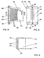
- the structure of the chamber 40 is shown in detail in FIGS. 4, 5, 6 and 15.
- the stack of metal sheets 42 for deionizing the arc is arranged on an insulating support 69 comprising two side cheeks 70, 72.
- the internal face of each cheek 70, 72 is provided with a plurality of ribs 74 delimiting a succession of grooves 76 for positioning the opposite edges of the sheets 42 and of the upper arc horn 46.
- At each cheek 70, 72, is associated by molding a half-plate 78, 80, frontal fixing, so as to constitute an insulating one-piece piece.
- the extinguishing chamber 40 is trapped between the two cheeks 70, 72, lateral for positioning the sheets 42, the support 69 and chamber 40 assembly being held in place by means of two flanges 82, 84, assembly.
- Two auxiliary fixing screws 86, 88 pass through the assembly flanges 82, 84, in the median plane of junction of the two half-plates 78, 80, coplanar with the support 69 insulating the chamber 40.
- Exhaust slots 89 are provided in the half plates 78.80, for the evacuation of the breaking gases towards the outdoor environment.
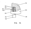
- the extraction of the chamber 40 makes it easier in particular to visually check the wear of the contact pads 36, 38, of each pole, by virtue of a reference mark 92 for viewing arranged on the corresponding cage 56 (FIG. 15).
- the reference 92 can be formed by a semi-open notch delimited by two edges R1 and R2.
- the front part of the contact fingers 54 located between the movable contact 38 and the arcing horn 44, has an extension 94, the end of which is opposite the mark 92 of the cage 56.
- the presence of the pressure springs 62 of contact varies the relative position of the contact fingers 54 with respect to the cage 56 as a function of the wear of the contacts 36, 38.
- the wear check takes place in the closed position of the circuit breaker after having armed the mechanism 26 energy accumulator by the arming lever 28, and controlled the closing of the contacts 36, 38, by unlocking the closing pawl (not shown).
- the maximum wear of the contacts 36, 38 is reached when the end of the extension 94 coincides with the edge R2 of the reference 92. Replacement of the pole contacts is then essential. The state and the insertion of the contacts are satisfactory, when the end of the extension 94 is located in the interval between the two edges R1 and R2 of the reference 92.
- This visual wear check of the contacts 36, 38 does not require disassembly of the housing 12 or of the mechanism 26 and can be carried out pole by pole, by simply unscrewing two fixing screws 86, 88, of the support 69 and extraction of the corresponding arc extinguishing chamber 40.
- the monobloc support 69 and arc extinguishing chamber 40 assembly is introduced in the longitudinal direction of the pole through the lateral opening 90 of the lower compartment 24 in the direction of the contacts.
- the insulating support 69 is blocked in translation by the tightening of the auxiliary screws 86, 88, and the upper arcing horn 46 is perfectly positioned with respect to the contact fingers 54 of the moving assembly .
- the two half-plates 78, 80 coplanar and contiguous with the insulating support 69 constitute a closure wall for the rectangular opening 90 of the lower compartment 24.
- auxiliary fixing screws 86 is screwed into an orifice in the base 18, while the other fixing screw 88 is introduced into an orifice in the intermediate casing 14.
- the closure wall In the inserted position of the chamber 40, the closure wall has a flat and continuous surface with the remaining lateral face of the insulating housing 12. The presence slots 89 in this wall allow the escape of the cutting gases to the outside.
- the insulating cage 56 comprises a plurality of cells 98 for housing the contact fingers 54, and is framed laterally by two parallel flanges 100, 102 extending in the longitudinal direction of the pole. Each flange 100, 102 carries a pin 104, positioned in a corresponding bearing 106 of the stirrup 65 for fixing the second pad 60.
- the cage 56 is pivotally mounted on the track 60 during the rotational movement of the switching rod 33 actuated by the mechanism 26.
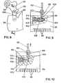
- the mechanical connection 68 between the switching rod 33 and the cage 56 of each pole is formed by a transmission rod 108, articulated on an axis 110 of a crank 112 wedged on the bar 33.
- the end of the rod 108 located opposite the axis 110, cooperates with a retractable coupling member 114, arranged at the interior of the cage 56.
- the coupling member 114 comprises a slide 116 mounted with limited sliding in a cylindrical housing 118 of the cage 56 extending perpendicularly to the rod 108.
- One of the ends of the slide 116 is extended by a coupling pin 120 intended to engage in an orifice or hole 122 in the connecting rod 108 under the action of a compression spring 124 (FIG. 9).
- the latter extends coaxially inside the housing 118, being interposed between the slide 116 and a plug 126 for closing the housing 118, located opposite the coupling pin 120.
- the slide 116 is provided on the other hand an annular groove 128 into which can be introduced a tool (not shown) capable of driving in translation the coupling member 114 towards the retracted position, against the force of the spring 124 ( figure 10).
- the mechanical connection 68 between the bar 33 and the cage 56 is then interrupted, so as to allow the disassembly of the downstream block 53.
- the mechanism 26 remains in place in the upper compartment 22, but is mechanically detached from the moving assembly of the pole.
- the insertion of the tool into the groove 128 of the slide 116 takes place through a rectangular orifice 130 formed in the body of the cage 56 (see FIG. 7) in line with the mobile slide 116.
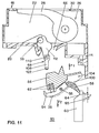
- the mounting of a pole is illustrated in FIG. 11, after the mechanism 26 and the bar 33 have been placed in the upper compartment 22 of the housing 12.
- the assembly of the downstream block 53 takes place at the rear of the housing 12 after removal of the base 18 and of the arc extinguishing chambers 40 of the different poles.
- the downstream block 53 of the movable contact of each pole is constituted by a sub-assembly comprising the cage 56, the contact fingers 54 with their respective braids 58 and springs 62 of contact pressure, and the second connection pad 60 equipped with the 'fixing bracket 65.
- the pivot axis 104 of the cage 56 is positioned in the bearings 106 of the stirrup 65 and the downstream block 53 is moved in the direction of the arrow F1 and fixed to the underside of the partition 20 of the intermediate casing 14 at by means of the screw 64 passing through the stirrup 65 of the pad 60.
- the mechanical connection 68 is coupled to the cage 56 in the disarmed open position of the mechanism 26. This operation requires the manual actuation of the bar 33 towards the closed position, and the displacement of the coupling member 114 by means of a tool towards the retracted position of FIG. 10, to authorize the installation of the transmission rod 108.
- the introduction of the neutralization tool of the coupling member 114 is carried out through the opening 90 of the housing 12 and through the orifice 130 of the cage 56.
- the release of the slide 116 then causes the introduction of the coupling axis 120 in the orifice 122 of the connecting rod 108, thanks to the relaxation of the r essort 124.
- the bar 33 is tilted counterclockwise towards the open position, shown in FIG. 3.
- the energy storage device of mechanism 26 is then armed by means of the arming lever 28 to cause the closing of the circuit breaker, followed by the verification of the depression of the contacts 36, 38, of the different poles.
- the final assembly of the circuit breaker 10 occurs after insertion of the arc extinguishing chambers 40 into the lateral openings 90 of the assembled housing 12 (see FIG. 2).
- Figure 13 shows the incorporation of a current limiting pole, comprising contacts 36, 38 with electrodynamic repulsion effect.
- the contact fingers 154 are pivotally mounted on a transverse axis 156 carried by a support 158 fixed to the insulating cage 56.
- the support 158 is provided with a curvilinear guide groove 160 the length of which corresponds to the electrodynamic repulsion stroke of the fingers 154, when a short-circuit current appears in the pole.
- the opening of the contacts 36, 38, by electrodynamic repulsion (in dotted lines in FIG. 13) is then confirmed by the triggering of the mechanism 26 causing the rotation of the bar 33 anticlockwise and the definitive opening of all the poles of the circuit breaker 10.
- the positioning of the limiting pole of FIG. 13 is carried out in the same manner as that used for the pole of FIGS. 3, 11 and 12, after fixing the stirrup 65 to the intermediate casing 14, and after coupling of the link mechanical 68 ( Figures 7 to 10).
- the disassembly of the poles of the circuit breaker 10 takes place in the opposite direction to the assembly described above, after having removed the base 18 from the housing 12 and the arc extinguishing chambers 40.
- the disassembly of the downstream block 53 takes place in the direction of arrow F2 (FIG. 11) after unscrewing the screw 64, and uncoupling the mechanical connection 68 with the bar 33.
- Any other type of pole can of course be adapted to the circuit breaker according to the breaking capacity and the protection and control functions of the circuits.
- connection pads 48, 60 of each pole are advantageously equipped with positioning wedges 160 which can be adapted in the cells of the base 18.
- the dimensions of the cells are identical for the whole range, and the thickness of the shims 160 varies according to the size.
- This arrangement makes it possible to use a standard insulating box 12, and to mount ranges of different cross-section in the same cell for ratings ranging from 800 A to 4000 A.
Landscapes
- Arc-Extinguishing Devices That Are Switches (AREA)
- Breakers (AREA)
Applications Claiming Priority (4)
| Application Number | Priority Date | Filing Date | Title |
|---|---|---|---|
| FR8516346A FR2589625B1 (fr) | 1985-10-31 | 1985-10-31 | Chaine cinematique de transmission entre le mecanisme de commande et les poles d'un disjoncteur electrique |
| FR8516346 | 1985-10-31 | ||
| FR8516345 | 1985-10-31 | ||
| FR8516345A FR2589624B1 (fr) | 1985-10-31 | 1985-10-31 | Disjoncteur electrique multipolaire a boitier isolant moule |
Publications (2)
| Publication Number | Publication Date |
|---|---|
| EP0225207A1 true EP0225207A1 (de) | 1987-06-10 |
| EP0225207B1 EP0225207B1 (de) | 1991-05-15 |
Family
ID=26224805
Family Applications (1)
| Application Number | Title | Priority Date | Filing Date |
|---|---|---|---|
| EP86402269A Expired - Lifetime EP0225207B1 (de) | 1985-10-31 | 1986-10-13 | Kinematische Übertragungskette zwischen dem Steuermechanismus und den Polen eines elektrischen Lastschalters mit einem gespritzten Isoliergehäuse |
Country Status (9)
| Country | Link |
|---|---|
| US (1) | US4764650A (de) |
| EP (1) | EP0225207B1 (de) |
| JP (1) | JPH0828173B2 (de) |
| CN (1) | CN1011450B (de) |
| BR (1) | BR8605349A (de) |
| CA (1) | CA1290798C (de) |
| DE (1) | DE3679291D1 (de) |
| IN (1) | IN168851B (de) |
| SG (1) | SG134392G (de) |
Cited By (37)
| Publication number | Priority date | Publication date | Assignee | Title |
|---|---|---|---|---|
| FR2619955A1 (fr) * | 1987-08-31 | 1989-03-03 | Merlin Gerin | Dispositif de coupure pour disjoncteur electrique multipolaire a contacts multiples |
| EP0325767A3 (en) * | 1988-01-26 | 1990-10-17 | Licentia Patent-Verwaltungs-Gmbh | Low-tension power circuit breaker with interchangeable contacts |
| EP0501885A1 (de) * | 1991-02-28 | 1992-09-02 | Schneider Electric Sa | Lastschalter |
| EP0652579A1 (de) * | 1993-11-04 | 1995-05-10 | Siemens Aktiengesellschaft | Schalter mit Lichtbogenlöschanordnung |
| WO1995028726A1 (de) * | 1994-04-19 | 1995-10-26 | Siemens Aktiengesellschaft | Niederspannungs-leistungsschalter mit einer schaltkammer |
| FR2722609A1 (fr) * | 1994-07-18 | 1996-01-19 | Schneider Electric Sa | Disjoncteur electrique a actionneur electromagnetique pour calibres eleves |
| WO1998002892A1 (de) * | 1996-07-12 | 1998-01-22 | Siemens Aktiengesellschaft | Schaltkontaktanordnung mit einer gelenkanordnung für einen kontakthebel |
| WO1998010451A1 (de) * | 1996-09-05 | 1998-03-12 | Siemens Aktiengesellschaft | Niederspannungs-leistungsschalter mit einer antriebsvorrichtung |
| FR2757675A1 (fr) * | 1996-12-23 | 1998-06-26 | Schneider Electric Sa | Disjoncteur electrique a ecran de securite |
| WO1998047161A1 (de) * | 1997-04-11 | 1998-10-22 | Aeg Niederspannungstechnik Gmbh & Co. Kg | Lichtbogenkammersystem |
| EP0727805A3 (de) * | 1995-02-16 | 1999-07-21 | Siemens Aktiengesellschaft | Kontakthebelbaugruppe für einen Niederspannungs-Leistungsschalter |
| WO1999067800A1 (fr) * | 1998-06-24 | 1999-12-29 | Schneider Electric Industries S.A. | Disjoncteur multipolaire basse tension de tenue electrodynamique elevee, dont l'arbre des poles est dispose dans le compartiment de logement des poles |
| EP0952596A3 (de) * | 1998-04-24 | 2000-06-14 | Siemens Aktiengesellschaft | Niederspannungs-Leistungsschalter mit einer einschiebbaren Stromschiene |
| EP0955658A3 (de) * | 1998-05-07 | 2000-08-23 | Eaton Corporation | Ellektrischer Schaltgerät mit verbesserten Kontaktarmträgervorrichtung |
| US6222146B1 (en) | 1996-07-15 | 2001-04-24 | Siemens Aktiengesellschaft | Arc extinguishing chamber for low voltage power switches |
| WO2001067477A1 (de) * | 2000-03-09 | 2001-09-13 | Siemens Aktiengesellschaft | Schaltpol für niederspannungs-schaltgeräte mit linear bewegbarem kontaktträger |
| WO1997033290A3 (de) * | 1996-03-08 | 2001-09-13 | Siemens Ag | Leistungsschalter mit isolierendem kontakthebelträger |
| EP1065683A3 (de) * | 1999-06-30 | 2002-03-27 | Siemens Aktiengesellschaft | Leistungsschalter mit Anschlussschienen für verschiedene Nennströme |
| US6657524B2 (en) | 2001-09-03 | 2003-12-02 | Siemens Aktiengesellschaft | Circuit breaker with a detachable connection between a switching contact arrangement and a drive apparatus which operates it, as well as a method for removal and installation of the switching contact arrangement |
| EP1770730A3 (de) * | 2005-09-29 | 2007-08-15 | Siemens Aktiengesellschaft | Elektrischer Schalter mit Lichtbogen-Löscheinrichtung |
| RU2310945C1 (ru) * | 2006-01-30 | 2007-11-20 | Общество с ограниченной ответственностью "Технос" | Выключатель быстродействующий автоматический постоянного тока |
| RU2310944C2 (ru) * | 2005-12-22 | 2007-11-20 | Общество с ограниченной ответственностью "Технос" | Выключатель быстродействующий автоматический постоянного тока |
| EP1914767A1 (de) | 2006-10-17 | 2008-04-23 | LS Industrial Systems Co., Ltd | Bewegliche Kontaktanordnung für einen Leistungsschalter |
| RU2334299C1 (ru) * | 2007-02-26 | 2008-09-20 | Общество с ограниченной ответственностью "Технос" | Электромагнитный привод коммутационного аппарата |
| EP1801835A3 (de) * | 2005-12-21 | 2008-12-17 | Mitsubishi Denki Kabushiki Kaisha | Schutzschalter |
| RU2344507C1 (ru) * | 2007-10-24 | 2009-01-20 | Общество с ограниченной ответственностью "Технос" | Автоматический воздушный выключатель |
| EP2061050A1 (de) | 2007-11-16 | 2009-05-20 | Schneider Electric Industries SAS | Elektrisches Unterbrechungsgerät mit Drehunterbrecherkontakt(en) |
| RU2366028C1 (ru) * | 2008-08-04 | 2009-08-27 | Общество с ограниченной ответственностью "Технос" | Выключатель автоматический быстродействующий |
| CZ301014B6 (cs) * | 1998-07-17 | 2009-10-14 | Schneider Electric Industries S. A. | Nízkonapetový vícepólový vypínac s velkou elektrodynamickou silou, jehož pólová hrídel se nachází v oddílu, kde jsou umísteny póly |
| RU2402096C1 (ru) * | 2009-02-02 | 2010-10-20 | Общество с ограниченной ответственностью "Технос" | Выключатель автоматический быстродействующий |
| RU2419912C1 (ru) * | 2009-12-23 | 2011-05-27 | Общество с ограниченной ответственностью "Технос" | Выключатель автоматический быстродействующий |
| RU2455722C2 (ru) * | 2010-10-11 | 2012-07-10 | Общество с ограниченной ответственностью "Технос" | Выключатель автоматический быстродействующий постоянного тока без механизма свободного расцепления |
| EP2541573A1 (de) * | 2011-06-30 | 2013-01-02 | Eaton Corporation | Trägerverbindungsisolator für einen Leistungsschalter |
| EP2293314A3 (de) * | 2009-09-08 | 2014-04-30 | Schneider Electric Industries SAS | Montagevorrichtung |
| RU2709189C1 (ru) * | 2016-08-30 | 2019-12-17 | Цзяньпин ЧЖАО | Рычаг прерывателя цепи |
| CN114141591A (zh) * | 2020-09-04 | 2022-03-04 | 上海电器股份有限公司人民电器厂 | 一种低压断路器的触头系统 |
| CN115714074A (zh) * | 2022-12-05 | 2023-02-24 | 航天银山电气有限公司 | 一种灭弧室弹簧装配工装 |
Families Citing this family (121)
| Publication number | Priority date | Publication date | Assignee | Title |
|---|---|---|---|---|
| JPH07101589B2 (ja) * | 1987-10-22 | 1995-11-01 | 富士電機株式会社 | 回路遮断器の開閉機構 |
| FR2624650B1 (fr) * | 1987-12-10 | 1990-04-06 | Merlin Gerin | Disjoncteur multipolaire a boitier moule de calibre eleve |
| FR2624649B1 (fr) * | 1987-12-10 | 1990-04-06 | Merlin Gerin | Disjoncteur multipolaire de calibre eleve constitue par deux boitiers accoles |
| US4876424A (en) * | 1988-09-19 | 1989-10-24 | Siemens Energy & Automation, Inc. | Barrier with a venting scheme for a circuit breaker |
| FR2650434B1 (fr) * | 1989-07-26 | 1995-11-24 | Merlin Gerin | Disjoncteur basse tension a contacts multiples et a fortes intensites |
| US5629869A (en) * | 1994-04-11 | 1997-05-13 | Abb Power T&D Company | Intelligent circuit breaker providing synchronous switching and condition monitoring |
| US5614881A (en) * | 1995-08-11 | 1997-03-25 | General Electric Company | Current limiting device |
| US5773778A (en) * | 1996-04-24 | 1998-06-30 | General Electric Company | Modular isolation block for circuit breaker contact arms |
| IT1292453B1 (it) | 1997-07-02 | 1999-02-08 | Aeg Niederspannungstech Gmbh | Gruppo rotante di contatti per interrutttori di alta portata |
| US6128168A (en) * | 1998-01-14 | 2000-10-03 | General Electric Company | Circuit breaker with improved arc interruption function |
| DE19819242B4 (de) | 1998-04-29 | 2005-11-10 | Ge Power Controls Polska Sp.Z.O.O. | Thermomagnetischer Leistungsschalter |
| US5899323A (en) * | 1998-05-07 | 1999-05-04 | Eaton Corporation | Electrical switching apparatus with contact finger guide |
| US6072136A (en) * | 1998-05-07 | 2000-06-06 | Eaton Corporation | Electrical switching apparatus with modular operating mechanism for mounting and controlling large compression close spring |
| US6114641A (en) * | 1998-05-29 | 2000-09-05 | General Electric Company | Rotary contact assembly for high ampere-rated circuit breakers |
| US6087913A (en) * | 1998-11-20 | 2000-07-11 | General Electric Company | Circuit breaker mechanism for a rotary contact system |
| US6037555A (en) * | 1999-01-05 | 2000-03-14 | General Electric Company | Rotary contact circuit breaker venting arrangement including current transformer |
| US6144540A (en) * | 1999-03-09 | 2000-11-07 | General Electric Company | Current suppressing circuit breaker unit for inductive motor protection |
| US6166344A (en) * | 1999-03-23 | 2000-12-26 | General Electric Company | Circuit breaker handle block |
| US6157286A (en) * | 1999-04-05 | 2000-12-05 | General Electric Company | High voltage current limiting device |
| US6262872B1 (en) | 1999-06-03 | 2001-07-17 | General Electric Company | Electronic trip unit with user-adjustable sensitivity to current spikes |
| US6268991B1 (en) | 1999-06-25 | 2001-07-31 | General Electric Company | Method and arrangement for customizing electronic circuit interrupters |
| US6218917B1 (en) | 1999-07-02 | 2001-04-17 | General Electric Company | Method and arrangement for calibration of circuit breaker thermal trip unit |
| US6188036B1 (en) | 1999-08-03 | 2001-02-13 | General Electric Company | Bottom vented circuit breaker capable of top down assembly onto equipment |
| US6710988B1 (en) | 1999-08-17 | 2004-03-23 | General Electric Company | Small-sized industrial rated electric motor starter switch unit |
| US6252365B1 (en) | 1999-08-17 | 2001-06-26 | General Electric Company | Breaker/starter with auto-configurable trip unit |
| US6175288B1 (en) | 1999-08-27 | 2001-01-16 | General Electric Company | Supplemental trip unit for rotary circuit interrupters |
| US6396369B1 (en) | 1999-08-27 | 2002-05-28 | General Electric Company | Rotary contact assembly for high ampere-rated circuit breakers |
| US6232570B1 (en) | 1999-09-16 | 2001-05-15 | General Electric Company | Arcing contact arrangement |
| US6326869B1 (en) | 1999-09-23 | 2001-12-04 | General Electric Company | Clapper armature system for a circuit breaker |
| US6239395B1 (en) | 1999-10-14 | 2001-05-29 | General Electric Company | Auxiliary position switch assembly for a circuit breaker |
| US6229413B1 (en) | 1999-10-19 | 2001-05-08 | General Electric Company | Support of stationary conductors for a circuit breaker |
| US6317018B1 (en) | 1999-10-26 | 2001-11-13 | General Electric Company | Circuit breaker mechanism |
| US6232856B1 (en) | 1999-11-02 | 2001-05-15 | General Electric Company | Magnetic shunt assembly |
| EP1098343B1 (de) | 1999-11-03 | 2005-09-21 | AEG Niederspannungstechnik GmbH & Co. KG | Drehkontaktanordnung für Schutzschalter |
| US6377144B1 (en) | 1999-11-03 | 2002-04-23 | General Electric Company | Molded case circuit breaker base and mid-cover assembly |
| DE19958945A1 (de) | 1999-11-26 | 2001-05-31 | Siemens Ag | Elektrisches Schaltgerät mit mehreren Gehäuseteilen |
| DE19958943A1 (de) | 1999-11-26 | 2001-05-31 | Siemens Ag | Niederspannungs-Leistungsschalter mit einem eine Vorderwand und eine Rückwand aufweisenden Gehäuse |
| US6300586B1 (en) | 1999-12-09 | 2001-10-09 | General Electric Company | Arc runner retaining feature |
| US6310307B1 (en) | 1999-12-17 | 2001-10-30 | General Electric Company | Circuit breaker rotary contact arm arrangement |
| US6184761B1 (en) | 1999-12-20 | 2001-02-06 | General Electric Company | Circuit breaker rotary contact arrangement |
| US6172584B1 (en) | 1999-12-20 | 2001-01-09 | General Electric Company | Circuit breaker accessory reset system |
| US6215379B1 (en) | 1999-12-23 | 2001-04-10 | General Electric Company | Shunt for indirectly heated bimetallic strip |
| US6281461B1 (en) | 1999-12-27 | 2001-08-28 | General Electric Company | Circuit breaker rotor assembly having arc prevention structure |
| US6346869B1 (en) | 1999-12-28 | 2002-02-12 | General Electric Company | Rating plug for circuit breakers |
| US6211758B1 (en) | 2000-01-11 | 2001-04-03 | General Electric Company | Circuit breaker accessory gap control mechanism |
| US6239677B1 (en) | 2000-02-10 | 2001-05-29 | General Electric Company | Circuit breaker thermal magnetic trip unit |
| US6429759B1 (en) | 2000-02-14 | 2002-08-06 | General Electric Company | Split and angled contacts |
| US6313425B1 (en) | 2000-02-24 | 2001-11-06 | General Electric Company | Cassette assembly with rejection features |
| US6281458B1 (en) | 2000-02-24 | 2001-08-28 | General Electric Company | Circuit breaker auxiliary magnetic trip unit with pressure sensitive release |
| US6204743B1 (en) | 2000-02-29 | 2001-03-20 | General Electric Company | Dual connector strap for a rotary contact circuit breaker |
| US6404314B1 (en) | 2000-02-29 | 2002-06-11 | General Electric Company | Adjustable trip solenoid |
| US6448521B1 (en) | 2000-03-01 | 2002-09-10 | General Electric Company | Blocking apparatus for circuit breaker contact structure |
| US6340925B1 (en) | 2000-03-01 | 2002-01-22 | General Electric Company | Circuit breaker mechanism tripping cam |
| US6379196B1 (en) | 2000-03-01 | 2002-04-30 | General Electric Company | Terminal connector for a circuit breaker |
| US6346868B1 (en) | 2000-03-01 | 2002-02-12 | General Electric Company | Circuit interrupter operating mechanism |
| US6211757B1 (en) | 2000-03-06 | 2001-04-03 | General Electric Company | Fast acting high force trip actuator |
| US6459349B1 (en) | 2000-03-06 | 2002-10-01 | General Electric Company | Circuit breaker comprising a current transformer with a partial air gap |
| US6366438B1 (en) | 2000-03-06 | 2002-04-02 | General Electric Company | Circuit interrupter rotary contact arm |
| US6496347B1 (en) | 2000-03-08 | 2002-12-17 | General Electric Company | System and method for optimization of a circuit breaker mechanism |
| US6429659B1 (en) | 2000-03-09 | 2002-08-06 | General Electric Company | Connection tester for an electronic trip unit |
| US6232859B1 (en) | 2000-03-15 | 2001-05-15 | General Electric Company | Auxiliary switch mounting configuration for use in a molded case circuit breaker |
| US6366188B1 (en) | 2000-03-15 | 2002-04-02 | General Electric Company | Accessory and recess identification system for circuit breakers |
| US6218919B1 (en) | 2000-03-15 | 2001-04-17 | General Electric Company | Circuit breaker latch mechanism with decreased trip time |
| US6421217B1 (en) | 2000-03-16 | 2002-07-16 | General Electric Company | Circuit breaker accessory reset system |
| US6459059B1 (en) | 2000-03-16 | 2002-10-01 | General Electric Company | Return spring for a circuit interrupter operating mechanism |
| US6479774B1 (en) | 2000-03-17 | 2002-11-12 | General Electric Company | High energy closing mechanism for circuit breakers |
| US6388213B1 (en) | 2000-03-17 | 2002-05-14 | General Electric Company | Locking device for molded case circuit breakers |
| US6476698B1 (en) | 2000-03-17 | 2002-11-05 | General Electric Company | Convertible locking arrangement on breakers |
| FR2806548B1 (fr) | 2000-03-17 | 2002-08-23 | Ge Power Controls France | Mecanisme extractible pour disjoncteurs |
| US6586693B2 (en) | 2000-03-17 | 2003-07-01 | General Electric Company | Self compensating latch arrangement |
| US6472620B2 (en) | 2000-03-17 | 2002-10-29 | Ge Power Controls France Sas | Locking arrangement for circuit breaker draw-out mechanism |
| US6639168B1 (en) | 2000-03-17 | 2003-10-28 | General Electric Company | Energy absorbing contact arm stop |
| US6373010B1 (en) | 2000-03-17 | 2002-04-16 | General Electric Company | Adjustable energy storage mechanism for a circuit breaker motor operator |
| US6559743B2 (en) | 2000-03-17 | 2003-05-06 | General Electric Company | Stored energy system for breaker operating mechanism |
| US6747535B2 (en) | 2000-03-27 | 2004-06-08 | General Electric Company | Precision location system between actuator accessory and mechanism |
| US6995640B2 (en) * | 2000-05-16 | 2006-02-07 | General Electric Company | Pressure sensitive trip mechanism for circuit breakers |
| US6373357B1 (en) | 2000-05-16 | 2002-04-16 | General Electric Company | Pressure sensitive trip mechanism for a rotary breaker |
| US6400245B1 (en) | 2000-10-13 | 2002-06-04 | General Electric Company | Draw out interlock for circuit breakers |
| US6806800B1 (en) | 2000-10-19 | 2004-10-19 | General Electric Company | Assembly for mounting a motor operator on a circuit breaker |
| US6531941B1 (en) | 2000-10-19 | 2003-03-11 | General Electric Company | Clip for a conductor in a rotary breaker |
| US6429760B1 (en) | 2000-10-19 | 2002-08-06 | General Electric Company | Cross bar for a conductor in a rotary breaker |
| US6362711B1 (en) | 2000-11-10 | 2002-03-26 | General Electric Company | Circuit breaker cover with screw locating feature |
| US6380829B1 (en) | 2000-11-21 | 2002-04-30 | General Electric Company | Motor operator interlock and method for circuit breakers |
| US6376788B1 (en) | 2001-01-08 | 2002-04-23 | Eaton Corporation | Magnetically collapsible toggle linkage for electrical switching apparatus |
| US6448522B1 (en) | 2001-01-30 | 2002-09-10 | General Electric Company | Compact high speed motor operator for a circuit breaker |
| US6476337B2 (en) | 2001-02-26 | 2002-11-05 | General Electric Company | Auxiliary switch actuation arrangement |
| US6882258B2 (en) * | 2001-02-27 | 2005-04-19 | General Electric Company | Mechanical bell alarm assembly for a circuit breaker |
| DE10132127C1 (de) * | 2001-06-28 | 2002-11-14 | Siemens Ag | Bewegbarer Kontaktträger für einen Niederspannungs-Leistungsschalter und Verfahren zu seiner Herstellung |
| US6507256B1 (en) * | 2001-08-17 | 2003-01-14 | General Electric Company | Auxiliary magnetic trip system |
| US6678135B2 (en) | 2001-09-12 | 2004-01-13 | General Electric Company | Module plug for an electronic trip unit |
| DE10148947C1 (de) * | 2001-09-28 | 2003-02-13 | Siemens Ag | Schaltkontaktanordnung eines Niederspannungs-Leistungsschalters |
| DE10149020C1 (de) * | 2001-09-28 | 2003-01-16 | Siemens Ag | Kontaktanordnung für Niederspannungs-Schaltgeräte |
| US6469882B1 (en) | 2001-10-31 | 2002-10-22 | General Electric Company | Current transformer initial condition correction |
| US6804101B2 (en) | 2001-11-06 | 2004-10-12 | General Electric Company | Digital rating plug for electronic trip unit in circuit breakers |
| US6437670B1 (en) | 2002-02-12 | 2002-08-20 | General Electric Company | Magnetic release system for a circuit breaker |
| RU2239907C1 (ru) * | 2003-04-02 | 2004-11-10 | Общество с ограниченной ответственностью "Технос" | Выключатель автоматический быстродействующий постоянного тока |
| RU2239253C1 (ru) * | 2003-05-05 | 2004-10-27 | Общество с ограниченной ответственностью "Технос" | Выключатель быстродействующий автоматический постоянного тока |
| DE102004002932B4 (de) * | 2004-01-14 | 2013-02-28 | Siemens Aktiengesellschaft | Lichtbogen-Löscheinrichtung für einen elektrischen Schalter |
| ITBG20050025A1 (it) | 2005-05-13 | 2006-11-14 | Abb Service Srl | Interruttore con migliorate caratteristiche di intercambiabilita' del comando. |
| ITBG20050026A1 (it) * | 2005-05-13 | 2006-11-14 | Abb Service Srl | Interruttore con equipaggio mobile sospeso |
| ITBG20050024A1 (it) * | 2005-05-13 | 2006-11-14 | Abb Service Srl | Interruttore installabile secondo diverse configurazioni operative |
| RU2296386C1 (ru) * | 2005-09-15 | 2007-03-27 | Общество с ограниченной ответственностью "Технос" | Выключатель автоматический быстродействующий |
| US7368677B2 (en) * | 2005-12-14 | 2008-05-06 | Eaton Corporation | Reverse bias hatchet reset spring |
| ITBG20060050A1 (it) * | 2006-10-06 | 2008-04-07 | Abb Service S Rl | Interruttore di bassa tensione con poli intercambiabili |
| CN101190552A (zh) * | 2006-11-29 | 2008-06-04 | 深圳富泰宏精密工业有限公司 | 模具结构 |
| RU2341842C1 (ru) * | 2007-05-18 | 2008-12-20 | Общество с ограниченной ответственностью "Технос" | Выключатель автоматический быстродействующий |
| RU2382431C1 (ru) * | 2008-06-17 | 2010-02-20 | Общество с ограниченной ответственностью "Технос" | Быстродействующий выключатель с датчиком скорости перемещения якоря и устройство управления током катушки электромагнита |
| FR2938969A1 (fr) * | 2008-11-21 | 2010-05-28 | Schneider Electric Ind Sas | Dispositif de coupure pour couper un courant continu bidirectionnel et installation a cellules photovoltaiques equipee d'un tel dispositif |
| KR101255475B1 (ko) | 2011-11-10 | 2013-04-16 | 엘에스산전 주식회사 | 배선용 차단기 |
| US9263216B2 (en) * | 2012-09-14 | 2016-02-16 | Carling Technologies, Inc. | Circuit breaker with arc shield |
| KR101513208B1 (ko) * | 2013-11-08 | 2015-04-17 | 엘에스산전 주식회사 | 배선용 차단기 |
| DE102014107634A1 (de) * | 2014-05-30 | 2015-12-03 | Eaton Electrical Ip Gmbh & Co. Kg | Schutzschalter mit verbesserter Befestigung einer Stromschiene |
| DE102014107630B4 (de) * | 2014-05-30 | 2020-01-30 | Eaton Intelligent Power Limited | Schutzschalter mit verbesserter Isolation der Schaltwelle |
| FR3027728B1 (fr) * | 2014-10-22 | 2017-12-08 | Socomec Sa | Dispositif de coupure d'arc electrique |
| CN106710993A (zh) * | 2015-11-12 | 2017-05-24 | 浙江正泰电器股份有限公司 | 万能式断路器灭弧室 |
| EP3389069B1 (de) * | 2017-04-11 | 2019-12-11 | Microelettrica Scientifica S.p.A. | Verbesserter schalter für anwendungen mit hohem gleichstrom oder hochspannung wie zum beispiel industrie- und/oder eisenbahnanwendungen |
| CN107633982B (zh) * | 2017-10-30 | 2019-10-25 | 现代重工(中国)电气有限公司 | 一种断路器 |
| CN108972597A (zh) * | 2018-07-26 | 2018-12-11 | 芜湖市越泽机器人科技有限公司 | 一种机器人抓取工具切换装置 |
| US10650993B1 (en) * | 2019-03-19 | 2020-05-12 | Siemens Industry, Inc. | Circuit breaker with enhanced arc extinguishing chamber |
| CN116168981B (zh) * | 2023-02-22 | 2023-11-17 | 浙江巨邦电器股份有限公司 | 塑壳断路器 |
| CN117877908B (zh) * | 2024-02-28 | 2024-09-10 | 常有电气有限公司 | 柱上断路器的生产工艺及其采用该工艺生产的柱上断路器 |
Citations (6)
| Publication number | Priority date | Publication date | Assignee | Title |
|---|---|---|---|---|
| BE561334A (de) * | ||||
| US2727111A (en) * | 1951-11-01 | 1955-12-13 | I T E Circuit Breaker Corp | Arc chute design for circuit breakers |
| DE2062762A1 (de) * | 1970-12-19 | 1972-07-06 | Bbc Brown Boveri & Cie | Selbstschalter in Isolierstoffgehäuse |
| DE2504007A1 (de) * | 1974-02-08 | 1975-08-14 | Schrack Elektrizitaets Ag E | Fehlerstrom- bzw. fehlerspannungsschutzschalter od. dgl. |
| GB2042263A (en) * | 1979-02-08 | 1980-09-17 | Terasaki Denki Sangyo Kk | Improvements in or relating to circuit interrupters |
| FR2451097A1 (fr) * | 1979-02-07 | 1980-10-03 | Terasaki Denki Sangyo Kk | Interrupteur de circuit electrique a air, mecanisme et boitier |
Family Cites Families (12)
| Publication number | Priority date | Publication date | Assignee | Title |
|---|---|---|---|---|
| US3004125A (en) * | 1959-06-18 | 1961-10-10 | Licentia Gmbh | Switch |
| US3636291A (en) * | 1965-06-08 | 1972-01-18 | Westinghouse Electric Corp | Electric switchgear with contact viewing and contact mounting means |
| US3472982A (en) * | 1966-07-29 | 1969-10-14 | Square D Co | Arc chute |
| US3821607A (en) * | 1972-12-29 | 1974-06-28 | Westinghouse Electric Corp | Circuit interrupter protective device |
| US4139754A (en) * | 1976-10-18 | 1979-02-13 | I-T-E Imperial Corporation | Stationary contact combination |
| JPS53141473A (en) * | 1977-05-17 | 1978-12-09 | Terasaki Denki Sangyo Kk | Air circuit breaker |
| US4277664A (en) * | 1979-08-24 | 1981-07-07 | Westinghouse Electric Corp. | Circuit breaker structure |
| FR2484136A1 (fr) * | 1980-06-06 | 1981-12-11 | Merlin Gerin | Contacts electriques perfectionnes pour disjoncteurs multipolaires a basse tension et procede de fabrication des contacts |
| JPS57194237U (de) * | 1981-06-03 | 1982-12-09 | ||
| US4527027A (en) * | 1982-07-16 | 1985-07-02 | Eaton Corporation | Molded case circuit breaker with improved high fault current interruption capability |
| DE3409579A1 (de) * | 1984-03-15 | 1985-09-19 | Siemens AG, 1000 Berlin und 8000 München | Befestigungsanordnung fuer lichtbogenkammern |
| US4679016A (en) * | 1986-01-08 | 1987-07-07 | General Electric Company | Interchangeable mechanism for molded case circuit breaker |
-
1986
- 1986-10-13 EP EP86402269A patent/EP0225207B1/de not_active Expired - Lifetime
- 1986-10-13 DE DE8686402269T patent/DE3679291D1/de not_active Expired - Fee Related
- 1986-10-16 US US06/919,434 patent/US4764650A/en not_active Expired - Fee Related
- 1986-10-17 IN IN823/MAS/86A patent/IN168851B/en unknown
- 1986-10-20 CA CA000520927A patent/CA1290798C/en not_active Expired - Fee Related
- 1986-10-29 JP JP61258073A patent/JPH0828173B2/ja not_active Expired - Fee Related
- 1986-10-29 CN CN86107135A patent/CN1011450B/zh not_active Expired
- 1986-10-30 BR BR8605349A patent/BR8605349A/pt not_active IP Right Cessation
-
1992
- 1992-12-30 SG SG1343/92A patent/SG134392G/en unknown
Patent Citations (6)
| Publication number | Priority date | Publication date | Assignee | Title |
|---|---|---|---|---|
| BE561334A (de) * | ||||
| US2727111A (en) * | 1951-11-01 | 1955-12-13 | I T E Circuit Breaker Corp | Arc chute design for circuit breakers |
| DE2062762A1 (de) * | 1970-12-19 | 1972-07-06 | Bbc Brown Boveri & Cie | Selbstschalter in Isolierstoffgehäuse |
| DE2504007A1 (de) * | 1974-02-08 | 1975-08-14 | Schrack Elektrizitaets Ag E | Fehlerstrom- bzw. fehlerspannungsschutzschalter od. dgl. |
| FR2451097A1 (fr) * | 1979-02-07 | 1980-10-03 | Terasaki Denki Sangyo Kk | Interrupteur de circuit electrique a air, mecanisme et boitier |
| GB2042263A (en) * | 1979-02-08 | 1980-09-17 | Terasaki Denki Sangyo Kk | Improvements in or relating to circuit interrupters |
Cited By (52)
| Publication number | Priority date | Publication date | Assignee | Title |
|---|---|---|---|---|
| EP0306382A1 (de) * | 1987-08-31 | 1989-03-08 | Merlin Gerin | Schalteranordnung für elektrische mehrpolige Schutzschalter mit mehreren Kontakten |
| US4877929A (en) * | 1987-08-31 | 1989-10-31 | Merlin Gerin | Breaking device for multipole electrical circuit breaker with multiple contacts |
| FR2619955A1 (fr) * | 1987-08-31 | 1989-03-03 | Merlin Gerin | Dispositif de coupure pour disjoncteur electrique multipolaire a contacts multiples |
| EP0325767A3 (en) * | 1988-01-26 | 1990-10-17 | Licentia Patent-Verwaltungs-Gmbh | Low-tension power circuit breaker with interchangeable contacts |
| EP0501885A1 (de) * | 1991-02-28 | 1992-09-02 | Schneider Electric Sa | Lastschalter |
| FR2673486A1 (fr) * | 1991-02-28 | 1992-09-04 | Telemecanique | Appareil interrupteur de courant. |
| EP0652579A1 (de) * | 1993-11-04 | 1995-05-10 | Siemens Aktiengesellschaft | Schalter mit Lichtbogenlöschanordnung |
| US5811748A (en) * | 1994-04-19 | 1998-09-22 | Siemens Aktiengesellschaft | Low-voltage power switch with a switching chamber |
| WO1995028726A1 (de) * | 1994-04-19 | 1995-10-26 | Siemens Aktiengesellschaft | Niederspannungs-leistungsschalter mit einer schaltkammer |
| FR2722609A1 (fr) * | 1994-07-18 | 1996-01-19 | Schneider Electric Sa | Disjoncteur electrique a actionneur electromagnetique pour calibres eleves |
| EP0693764A1 (de) * | 1994-07-18 | 1996-01-24 | Schneider Electric Sa | Elektrischer Lastschalter mit elektromagnetischem Betätiger für Hochstrom |
| CN1052332C (zh) * | 1994-07-18 | 2000-05-10 | 施耐德电器工业公司 | 电路断路器 |
| EP0727805A3 (de) * | 1995-02-16 | 1999-07-21 | Siemens Aktiengesellschaft | Kontakthebelbaugruppe für einen Niederspannungs-Leistungsschalter |
| WO1997033290A3 (de) * | 1996-03-08 | 2001-09-13 | Siemens Ag | Leistungsschalter mit isolierendem kontakthebelträger |
| WO1998002892A1 (de) * | 1996-07-12 | 1998-01-22 | Siemens Aktiengesellschaft | Schaltkontaktanordnung mit einer gelenkanordnung für einen kontakthebel |
| US6222146B1 (en) | 1996-07-15 | 2001-04-24 | Siemens Aktiengesellschaft | Arc extinguishing chamber for low voltage power switches |
| WO1998010451A1 (de) * | 1996-09-05 | 1998-03-12 | Siemens Aktiengesellschaft | Niederspannungs-leistungsschalter mit einer antriebsvorrichtung |
| FR2757675A1 (fr) * | 1996-12-23 | 1998-06-26 | Schneider Electric Sa | Disjoncteur electrique a ecran de securite |
| WO1998047161A1 (de) * | 1997-04-11 | 1998-10-22 | Aeg Niederspannungstechnik Gmbh & Co. Kg | Lichtbogenkammersystem |
| CN1087479C (zh) * | 1997-04-11 | 2002-07-10 | Aeg低压技术股份有限两合公司 | 电弧腔系统 |
| US6207916B1 (en) * | 1997-04-11 | 2001-03-27 | General Electric Company | Electric arc explosion chamber system |
| EP0952596A3 (de) * | 1998-04-24 | 2000-06-14 | Siemens Aktiengesellschaft | Niederspannungs-Leistungsschalter mit einer einschiebbaren Stromschiene |
| EP0955658A3 (de) * | 1998-05-07 | 2000-08-23 | Eaton Corporation | Ellektrischer Schaltgerät mit verbesserten Kontaktarmträgervorrichtung |
| US6317019B1 (en) | 1998-06-24 | 2001-11-13 | Square D Company | Low-voltage multipole circuit breaker with high electrodynamic resistance, whereof the pole shaft is arranged in the compartment housing the poles |
| FR2780549A1 (fr) * | 1998-06-24 | 1999-12-31 | Schneider Electric Ind Sa | Disjoncteur multipolaire basse tension de tenue electrodynamique elevee, dont l'arbre des poles est dispose dans le compartiment de logement des poles |
| WO1999067800A1 (fr) * | 1998-06-24 | 1999-12-29 | Schneider Electric Industries S.A. | Disjoncteur multipolaire basse tension de tenue electrodynamique elevee, dont l'arbre des poles est dispose dans le compartiment de logement des poles |
| CZ301014B6 (cs) * | 1998-07-17 | 2009-10-14 | Schneider Electric Industries S. A. | Nízkonapetový vícepólový vypínac s velkou elektrodynamickou silou, jehož pólová hrídel se nachází v oddílu, kde jsou umísteny póly |
| EP1065683A3 (de) * | 1999-06-30 | 2002-03-27 | Siemens Aktiengesellschaft | Leistungsschalter mit Anschlussschienen für verschiedene Nennströme |
| WO2001067477A1 (de) * | 2000-03-09 | 2001-09-13 | Siemens Aktiengesellschaft | Schaltpol für niederspannungs-schaltgeräte mit linear bewegbarem kontaktträger |
| US6803844B2 (en) | 2000-03-09 | 2004-10-12 | Siemens Aktiengesellschaft | Switchgear for low-voltage switching units with a linearly displaceable contact support |
| EP1288980A3 (de) * | 2001-09-03 | 2004-11-24 | Siemens Aktiengesellschaft | Leistungsschalter mit einer lösbaren Verbindung zwischen einer Schaltkontaktanordnung und einer diese betätigenden Antriebsvorrichtung sowie Verfahren zum Aus- und Einbau der Schaltkontaktanordnung |
| US6657524B2 (en) | 2001-09-03 | 2003-12-02 | Siemens Aktiengesellschaft | Circuit breaker with a detachable connection between a switching contact arrangement and a drive apparatus which operates it, as well as a method for removal and installation of the switching contact arrangement |
| EP1770730A3 (de) * | 2005-09-29 | 2007-08-15 | Siemens Aktiengesellschaft | Elektrischer Schalter mit Lichtbogen-Löscheinrichtung |
| EP1801835A3 (de) * | 2005-12-21 | 2008-12-17 | Mitsubishi Denki Kabushiki Kaisha | Schutzschalter |
| RU2310944C2 (ru) * | 2005-12-22 | 2007-11-20 | Общество с ограниченной ответственностью "Технос" | Выключатель быстродействующий автоматический постоянного тока |
| RU2310945C1 (ru) * | 2006-01-30 | 2007-11-20 | Общество с ограниченной ответственностью "Технос" | Выключатель быстродействующий автоматический постоянного тока |
| EP1914767A1 (de) | 2006-10-17 | 2008-04-23 | LS Industrial Systems Co., Ltd | Bewegliche Kontaktanordnung für einen Leistungsschalter |
| RU2334299C1 (ru) * | 2007-02-26 | 2008-09-20 | Общество с ограниченной ответственностью "Технос" | Электромагнитный привод коммутационного аппарата |
| RU2344507C1 (ru) * | 2007-10-24 | 2009-01-20 | Общество с ограниченной ответственностью "Технос" | Автоматический воздушный выключатель |
| EP2061050A1 (de) | 2007-11-16 | 2009-05-20 | Schneider Electric Industries SAS | Elektrisches Unterbrechungsgerät mit Drehunterbrecherkontakt(en) |
| CN101477923A (zh) * | 2007-11-16 | 2009-07-08 | 施耐德电器工业公司 | 具有旋转的可动触头的电气开关单元 |
| FR2923940A1 (fr) * | 2007-11-16 | 2009-05-22 | Schneider Electric Ind Sas | Appareil electrique de coupure a contact(s)mobile(s) rotatif(s). |
| CN101477923B (zh) * | 2007-11-16 | 2013-06-19 | 施耐德电器工业公司 | 具有旋转的可动触头的电气开关单元 |
| RU2366028C1 (ru) * | 2008-08-04 | 2009-08-27 | Общество с ограниченной ответственностью "Технос" | Выключатель автоматический быстродействующий |
| RU2402096C1 (ru) * | 2009-02-02 | 2010-10-20 | Общество с ограниченной ответственностью "Технос" | Выключатель автоматический быстродействующий |
| EP2293314A3 (de) * | 2009-09-08 | 2014-04-30 | Schneider Electric Industries SAS | Montagevorrichtung |
| RU2419912C1 (ru) * | 2009-12-23 | 2011-05-27 | Общество с ограниченной ответственностью "Технос" | Выключатель автоматический быстродействующий |
| RU2455722C2 (ru) * | 2010-10-11 | 2012-07-10 | Общество с ограниченной ответственностью "Технос" | Выключатель автоматический быстродействующий постоянного тока без механизма свободного расцепления |
| EP2541573A1 (de) * | 2011-06-30 | 2013-01-02 | Eaton Corporation | Trägerverbindungsisolator für einen Leistungsschalter |
| RU2709189C1 (ru) * | 2016-08-30 | 2019-12-17 | Цзяньпин ЧЖАО | Рычаг прерывателя цепи |
| CN114141591A (zh) * | 2020-09-04 | 2022-03-04 | 上海电器股份有限公司人民电器厂 | 一种低压断路器的触头系统 |
| CN115714074A (zh) * | 2022-12-05 | 2023-02-24 | 航天银山电气有限公司 | 一种灭弧室弹簧装配工装 |
Also Published As
| Publication number | Publication date |
|---|---|
| IN168851B (de) | 1991-06-29 |
| JPS62105332A (ja) | 1987-05-15 |
| EP0225207B1 (de) | 1991-05-15 |
| CA1290798C (en) | 1991-10-15 |
| CN86107135A (zh) | 1987-04-29 |
| BR8605349A (pt) | 1987-08-04 |
| CN1011450B (zh) | 1991-01-30 |
| SG134392G (en) | 1993-03-12 |
| US4764650A (en) | 1988-08-16 |
| JPH0828173B2 (ja) | 1996-03-21 |
| DE3679291D1 (de) | 1991-06-20 |
Similar Documents
| Publication | Publication Date | Title |
|---|---|---|
| EP0225207B1 (de) | Kinematische Übertragungskette zwischen dem Steuermechanismus und den Polen eines elektrischen Lastschalters mit einem gespritzten Isoliergehäuse | |
| EP0064906B1 (de) | Mehrpoliger Schutzschalter mit auswechselbarer magnetothermischer Auslöseeinheit | |
| EP0619590B1 (de) | Mehrpoliger Schutzschalter mit modularem Zusammenbau | |
| EP1090404B1 (de) | Mehrpoliger niederspannungsleistungschalter mit hoher elektrodynamischer festigkeit, deren polschaft in dem aufnahmeraum der pole angeordnet ist | |
| FR2638563A1 (fr) | Dispositif de securite pour appareil de commutation realise par l'assemblage de plusieurs elements modulaires amovibles | |
| BE898480A (fr) | Ensemble disjoncteur. | |
| EP0829890A1 (de) | Mehrphasiger elektrischer Schalter mit einer Schaltwelle je Phase | |
| FR2495825A1 (fr) | Disjoncteur multipolaire synchronise, constitue par plusieurs ensembles et comprenant une tige de liaison mutuelle | |
| FR2782579A1 (fr) | Appareillage electrique de coupure comportant un disjoncteur embrochable et un dispositif indiquant l'etat du disjoncteur | |
| FR2818434A1 (fr) | Appareil de coupure electrique pour installation electrique | |
| FR2589625A1 (fr) | Chaine cinematique de transmission entre le mecanisme de commande et les poles d'un disjoncteur electrique | |
| EP2894647A1 (de) | Unipolarer Abschaltblock und mit einem solchen Block ausgestattete Abschaltvorrichtung | |
| EP0649155A1 (de) | Doppelte Lichtbogenlaufschiene für die Lichtbogenleitkammer eines Schutzschalters | |
| FR2495826A1 (fr) | Disjoncteur miniature a haut pouvoir de coupure | |
| EP0619592B1 (de) | Elektrischer Schutzschalter mit elektrodynamischer Kontaktabstossung und mit Doppellöschkammern | |
| EP3367415B1 (de) | Stromunterbrechungsgerät mit trennbaren elektrischen kontakten und zur unterbrechung in der luft | |
| FR2920251A1 (fr) | Dispositif de coupure pour appareillage electrique de commutation | |
| EP2936529B1 (de) | Einheitlicher abschaltblock und abschaltvorrichtung, insbesondere berührungsschalter mit mindestens einem solchen block | |
| FR2589624A1 (fr) | Disjoncteur electrique multipolaire a boitier isolant moule | |
| EP1103996B2 (de) | Abschaltvorrichtung für ein Schaltgerät | |
| FR2638017A1 (fr) | Interrupteur electrique multipolaire a basse tension pour calibres eleves | |
| EP4186084A1 (de) | Lichtbogenlöschkammer für eine elektrische schutzvorrichtung und elektrische schutzvorrichtung mit mindestens einer solchen löschkammer | |
| EP1842269A2 (de) | Einrichtung zum schutz elektrischer installationen mit verbesserter unterbrecherkapazität | |
| EP3266030A1 (de) | Unterbrechungspolsteuerungssystem mit übersteuerungs- und schutzschaltervorrichtung | |
| EP0045672A1 (de) | Kleinschalter mit Abschaltung des Nulleiters und des Phasenleiters |
Legal Events
| Date | Code | Title | Description |
|---|---|---|---|
| PUAI | Public reference made under article 153(3) epc to a published international application that has entered the european phase |
Free format text: ORIGINAL CODE: 0009012 |
|
| AK | Designated contracting states |
Kind code of ref document: A1 Designated state(s): DE GB IT SE |
|
| 17P | Request for examination filed |
Effective date: 19871009 |
|
| 17Q | First examination report despatched |
Effective date: 19900213 |
|
| GRAA | (expected) grant |
Free format text: ORIGINAL CODE: 0009210 |
|
| AK | Designated contracting states |
Kind code of ref document: B1 Designated state(s): DE GB IT SE |
|
| REF | Corresponds to: |
Ref document number: 3679291 Country of ref document: DE Date of ref document: 19910620 |
|
| ITF | It: translation for a ep patent filed | ||
| GBT | Gb: translation of ep patent filed (gb section 77(6)(a)/1977) | ||
| PLBE | No opposition filed within time limit |
Free format text: ORIGINAL CODE: 0009261 |
|
| STAA | Information on the status of an ep patent application or granted ep patent |
Free format text: STATUS: NO OPPOSITION FILED WITHIN TIME LIMIT |
|
| 26N | No opposition filed | ||
| EAL | Se: european patent in force in sweden |
Ref document number: 86402269.4 |
|
| PGFP | Annual fee paid to national office [announced via postgrant information from national office to epo] |
Ref country code: SE Payment date: 19991007 Year of fee payment: 14 |
|
| PGFP | Annual fee paid to national office [announced via postgrant information from national office to epo] |
Ref country code: GB Payment date: 20001011 Year of fee payment: 15 |
|
| PG25 | Lapsed in a contracting state [announced via postgrant information from national office to epo] |
Ref country code: SE Free format text: THE PATENT HAS BEEN ANNULLED BY A DECISION OF A NATIONAL AUTHORITY Effective date: 20001030 |
|
| EUG | Se: european patent has lapsed |
Ref document number: 86402269.4 |
|
| PG25 | Lapsed in a contracting state [announced via postgrant information from national office to epo] |
Ref country code: GB Free format text: LAPSE BECAUSE OF NON-PAYMENT OF DUE FEES Effective date: 20011013 |
|
| REG | Reference to a national code |
Ref country code: GB Ref legal event code: IF02 |
|
| GBPC | Gb: european patent ceased through non-payment of renewal fee |
Effective date: 20011013 |
|
| PGFP | Annual fee paid to national office [announced via postgrant information from national office to epo] |
Ref country code: DE Payment date: 20041005 Year of fee payment: 19 |
|
| PG25 | Lapsed in a contracting state [announced via postgrant information from national office to epo] |
Ref country code: IT Free format text: LAPSE BECAUSE OF NON-PAYMENT OF DUE FEES;WARNING: LAPSES OF ITALIAN PATENTS WITH EFFECTIVE DATE BEFORE 2007 MAY HAVE OCCURRED AT ANY TIME BEFORE 2007. THE CORRECT EFFECTIVE DATE MAY BE DIFFERENT FROM THE ONE RECORDED. Effective date: 20051013 |
|
| PG25 | Lapsed in a contracting state [announced via postgrant information from national office to epo] |
Ref country code: DE Free format text: LAPSE BECAUSE OF NON-PAYMENT OF DUE FEES Effective date: 20060503 |