EP0225246A1 - Verfahren und Vorrichtung zum Behandeln von textilen Materialien auf Materialträgern - Google Patents
Verfahren und Vorrichtung zum Behandeln von textilen Materialien auf Materialträgern Download PDFInfo
- Publication number
- EP0225246A1 EP0225246A1 EP86402543A EP86402543A EP0225246A1 EP 0225246 A1 EP0225246 A1 EP 0225246A1 EP 86402543 A EP86402543 A EP 86402543A EP 86402543 A EP86402543 A EP 86402543A EP 0225246 A1 EP0225246 A1 EP 0225246A1
- Authority
- EP
- European Patent Office
- Prior art keywords
- treatment
- material carrier
- enclosure
- installation according
- coils
- Prior art date
- Legal status (The legal status is an assumption and is not a legal conclusion. Google has not performed a legal analysis and makes no representation as to the accuracy of the status listed.)
- Granted
Links
- 239000000463 material Substances 0.000 title claims abstract description 150
- 239000004753 textile Substances 0.000 title claims abstract description 24
- 238000000034 method Methods 0.000 title claims abstract description 23
- 239000000969 carrier Substances 0.000 title claims description 22
- 238000011282 treatment Methods 0.000 claims abstract description 97
- 238000009434 installation Methods 0.000 claims abstract description 57
- 239000012530 fluid Substances 0.000 claims abstract description 52
- 238000004061 bleaching Methods 0.000 claims abstract description 9
- 238000001035 drying Methods 0.000 claims abstract description 9
- 238000004043 dyeing Methods 0.000 claims abstract description 9
- 238000005406 washing Methods 0.000 claims abstract description 9
- 238000004804 winding Methods 0.000 claims abstract description 9
- 238000009987 spinning Methods 0.000 claims abstract description 7
- 238000000605 extraction Methods 0.000 claims abstract description 5
- 238000012545 processing Methods 0.000 claims description 17
- 238000005192 partition Methods 0.000 claims description 8
- 230000002441 reversible effect Effects 0.000 claims description 8
- 239000011261 inert gas Substances 0.000 claims description 6
- 238000007789 sealing Methods 0.000 claims description 6
- 230000003068 static effect Effects 0.000 claims description 4
- 238000006073 displacement reaction Methods 0.000 claims description 2
- 239000007788 liquid Substances 0.000 description 5
- 240000008042 Zea mays Species 0.000 description 4
- 239000012876 carrier material Substances 0.000 description 2
- 238000004891 communication Methods 0.000 description 2
- 239000000835 fiber Substances 0.000 description 2
- 239000000126 substance Substances 0.000 description 2
- XLYOFNOQVPJJNP-UHFFFAOYSA-N water Substances O XLYOFNOQVPJJNP-UHFFFAOYSA-N 0.000 description 2
- 238000012550 audit Methods 0.000 description 1
- 210000004027 cell Anatomy 0.000 description 1
- 238000010438 heat treatment Methods 0.000 description 1
- 238000007654 immersion Methods 0.000 description 1
- 238000012432 intermediate storage Methods 0.000 description 1
- 230000000670 limiting effect Effects 0.000 description 1
- 230000002829 reductive effect Effects 0.000 description 1
- 230000000284 resting effect Effects 0.000 description 1
- 238000003860 storage Methods 0.000 description 1
- 238000012546 transfer Methods 0.000 description 1
- 238000013519 translation Methods 0.000 description 1
Images







Classifications
-
- D—TEXTILES; PAPER
- D06—TREATMENT OF TEXTILES OR THE LIKE; LAUNDERING; FLEXIBLE MATERIALS NOT OTHERWISE PROVIDED FOR
- D06B—TREATING TEXTILE MATERIALS USING LIQUIDS, GASES OR VAPOURS
- D06B5/00—Forcing liquids, gases or vapours through textile materials to effect treatment, e.g. washing, dyeing, bleaching, sizing impregnating
- D06B5/12—Forcing liquids, gases or vapours through textile materials to effect treatment, e.g. washing, dyeing, bleaching, sizing impregnating through materials of definite length
- D06B5/16—Forcing liquids, gases or vapours through textile materials to effect treatment, e.g. washing, dyeing, bleaching, sizing impregnating through materials of definite length through yarns, threads or filaments
Definitions
- the subject of the invention is a method and an installation for the treatment, using a fluid, of textile materials on material carriers.
- It relates, in particular, to a method and an installation for the treatment of textile materials by circulation through said materials of a liquid or bath, for example, and without this indication having any limiting nature whatsoever, a washing bath. , bleaching, dyeing or the like, or a drying treatment using a gaseous fluid such as air.
- an autoclave has already been proposed, for example in EP-Al-0 110 058, capable of receiving one or more material carriers which can be introduced and / or extracted from the autoclave, by means of trolleys, each material carrier having a multiplicity of vertical rods on which are threaded, in the case of spools, the textile materials to be treated.
- the treatment is carried out at a bath ratio of the order of 1: 6 and if the loading and / or unloading of the autoclave using the material carriers is simpler than in certain installations.
- the cited document is silent as to how to load said material carriers.
- the entry or exit of the bath is done laterally, so that treatment of the "non-submerged" type is not possible.
- the object of the invention is to provide a method and an installation for the treatment, using a fluid, of textile materials on a material carrier which overcomes the disadvantages of the methods and known installations on the one hand and, on the other hand, further increases the productivity characteristics compared to installations comprising an autoclave of the type described immediately above, while allowing treatments not possible with this autoclave.
- an object of the invention to provide a method and an installation for the treatment, using a fluid, of textile materials on material carriers which, while considerably reducing costs treatment compared to known processes and installations, however, lead to finished products of the same quality or of higher quality than that of the products obtained by the processes and installations of the prior art.
- An installation according to the invention for the treatment such as washing, bleaching, dyeing, drying or the like of pieces of textile material by means of a treatment fluid in an apparatus comprising an external enclosure provided with a reversible circuit of treatment fluid, and at least one material carrier on which the parts to be treated are placed, suitable for entering and / or leaving said device for loading and / or unloading said pieces in and out of the device is characterized in that that the external enclosure comprises at least one entry and exit door of the material carrier, means for guiding said material carrier in the vicinity of the bottom of said apparatus, means for movement of said material carrier on said guide means, at least one inlet and one outlet for the fluid circuit in the bottom of said enclosure, as well as combined means on the material carrier and in the bottom of the enclosure to establish and ensure the continuity of the fluid circuit treatment from an apparatus for circulating it.
- the external enclosure of the treatment apparatus is cylindrical in shape and comprises, inside, vertical walls formed by watertight boxes arranged inside the enclosure and which define one or more parallelepipedic volumes (s) for receiving the material carrier (s).
- the enclosure of the processing apparatus is of generally parallelepipedal shape, with a cross section corresponding to that of one or advantageously a multiplicity of material carriers.
- the entry and exit door of the processing apparatus is a vertically sliding door.
- the door is a pivoting door, advantageously hinged in the upper part or on the side of the external enclosure that it is intended to close.
- the apparatus is provided with two doors, one of which is assigned to the input of the material carrier (s) and the other of which is assigned to the output of the material carrier (s) ci, the two said doors being either of the vertical sliding type or of the pivoting type.
- the material carrier is capable of being loaded and unloaded by means of modules carrying the coils, the enclosure of the corresponding processing apparatus then , in cross section, to that of one or advantageously of a multiplicity of modules.
- each module is provided with partition and gripping means secured to their upper part by a rigid grid, the drawing of which corresponds to the drawing, in plan, of the distribution of the stacks of coils.
- the straight section or planar contour of the module corresponds to that of a transport carriage suitable for receiving the module and which is used for moving it between the output of winding and spinning means. and a material carrier loading station.
- the material carrier is provided with clarinets or bayonets erected on the bottom of the material carrier, the latter being organized to receive a whole number of modules, the relative arrangement and the number of bayonets or clarinets of the carrier -Materials being chosen to correspond to the arrangement and the number of stacks of coils carried by all of the modules provided to cooperate with said material carrier.
- the latter whether it is of the distribution box type or of lower plate, is provided with at least one end piece forming part of the circuit for circulation of treatment fluid, seal means being provided for sealing said circuit. .
- said seal means result from the cooperation of said plate with seals carried, respectively, by a plate distant from the bottom of the enclosure of the apparatus and, on the other hand, by rules or the like integral with the door or doors of said apparatus, said plate being pierced with openings for communication between the interior of the enclosure in which the material carrier is housed with spaces into which the end fittings inlet and / or outlet of the treatment fluid into said enclosure.
- the material holder comprises a tank of substantially parallelepiped shape, with an access door to the volume inside the tank and at least a pair of support members for the upper loops of said skeins, said members being arranged parallel to each other in the vicinity of the upper part of the tank, which comprises, at its lower part means for connecting its internal volume to the treatment fluid circuit.
- the tank further comprises before tagging grid means to promote the distribution of the treatment fluid inside said volume and also, preferably, a second pair of members extending in the vicinity of the bottom of said tank for holding bars passing through loops lower skeins and intended to prevent them from becoming entangled with each other during treatment.
- the means of movement on the ground of the material carrier are advantageously of the wheeled type and the installation preferably comprises rails for guiding the material carrier in its movements of translation, introduction and / or extraction of the material. treatment apparatus.
- the invention also provides that the means of movement on the ground of the material carrier are associated with organized means to allow a vertical translational movement of the material carrier relative to the ground, this movement being used to, in the treatment device, establishing and ensuring the continuity of a circuit for circulation of the treatment fluid, advantageously using clamping means of the material holder provided in a cover or in the upper part of the external enclosure of the apparatus.
- An installation according to the invention allows the implementation of short or very short baths of the order of 1/4, with the consequence of significant savings in water, heating calories and quantities of chemicals.
- the invention provides that the apparatus for its circulation is organized to allow, at will, a circulation of said bath from the inside to the outside of the coils, or in the direction reverse, that is to say from outside to inside or alternately, in one direction and the other.
- the treatment apparatus can be operated at atmospheric pressure.
- the external enclosure advantageously has inside, and in the vicinity of its closed part, a vertical partition allowing circulation of the bath of treatment at the lower part. lower of said partition, as described for example in EP-Al-0 135 450, the expansion of the bath then taking place in the rear part of the enclosure.
- An installation according to the invention lends itself particularly well to the automation of its operation, in particular to robotization.
- the subject of the invention is also a method for the treatment in an apparatus of pieces of textile materials introduced and / or extracted from said apparatus using a material carrier on which said pieces are suitable for being loaded, said treatment as washing, bleaching, dyeing, drying or the like being carried out using a treatment fluid circulating through said materials, the method being characterized in that the loading of said parts onto the material carrier takes place by simultaneous introduction of a plurality of parts, in that the circulation through said parts of the treatment fluid takes place by means of a reversible fluid circuit whose inlet and outlet open into the bottom of said device and in that the unloading of said parts out of the material holder also takes place by simultaneous extraction of said plurality of parts.
- Such a process can be carried out with extremely short bath ratios, of the order of 1/4 and, in particular, the treatment can be of the "non-submerged" type, that is to say of the type in which the fluid bath level in the non-operating condition of the device is at most equal to the level of the lowest parts contained in the device.
- the invention provides that the loading and / or unloading of the plurality of stacks of reels is carried out by grouping together at the outlet of the spinning and winding means said stacks coils on a handling module where they are regularly arranged, advantageously according to a drawing having, in plan, an arrangement with rows and columns, the module then being of substantially rectangular cross section.
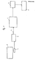
- FIG. 1 very schematically shows an installation according to the invention for the treatment, using a fluid, of textile materials on material carriers and in the case of an installation for processing coils or the like.
- Such an installation comprises a station A for winding and spinning, a station B for loading the bobbins from station A onto a material carrier, an apparatus C for processing textile materials in the form of bobbins of threads, rovings, ribbons or the like, a station D for unloading the material carriers at their exit from the apparatus C and a station E where said treated textile materials are taken up for a subsequent operation.
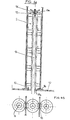
- the coils 2 from the winding and spinning means A are positioned on a storage module 11 placed prior to the start of loading the coils 2 on a carriage 7, FIGS. 1, 2 and 3.
- said module is of rectangular plan outline and comprises partition and gripping means 16 defining in plan a drawing with rows and columns of stacks of three, four or five coils, each of axis llc at the intersection of a row and a column.
- each stack of coils 2 rests on a tubular base 10, a recess 10a of which is capable of cooperating with a means 16 for gripping the batteries.
- All the partition and gripping means 16 are secured at their upper part by a rigid grid 16a, FIG. 2, with which is associated, in the upper part, an eye lld, FIG. 2 which, when the module furnished with coils is brought by the carriage 7 at station B allows simultaneous loading on a material carrier 1 of all of the coils of a module.
- each stack of coils is connected by the axial channel which it presents on a clarinet with a perforated tube or a bayonet 13 with a star profile whose upper end 13a is threaded and which is integral with the material holder 1
- the clarinets or bayonets 13 of the latter being arranged on the upper plate 12 of the box 12a of the material holder in geometrical correspondence of the stacks of coils 2 lining the module 11, it is all of its coils which is loaded on the door -materials 1 in a single transfer operation.
- each stack of coils 2 rests on the plate 12 of the box 12a of the material carrier 1 by a base 10, which simultaneously seals in contact with said plate, while the solidity of each pile is reinforced.
- a clamping device with plate 15 and nut 14 suitable for cooperating with the threaded part 13a of a bayonet 13 and advantageously common to a plurality of stacks.
- the dimensions and the plan outline of a material carrier 1 are preferably as shown in FIG. 4, that is to say provided to allow the loading of a certain number of modules 11, for example eight in the 'Example shown, and which are referenced 11 1 , 11 2 , 11 3 , etc ...
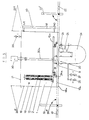
- this comprises, in a first embodiment, a rectangular tank or enclosure 19, the cross section of which right corresponding to that of a material holder and which is provided with entry and exit doors 20E and 20S, respectively, produced here as sliding, vertical doors, other executions being of course possible, in particular a realization with a single entry and exit door too, slidingly mounted in a vertical plane or pivotally mounted in the upper part of the enclosure as shown in FIG. 10.
- the tank or enclosure 19 is closed by a cover 21 crossed by a clamping device 30, the role of which will be explained below, while on the bottom 18a of the tank 19 are rails 17a with which cooperate the wheels 31a of four axle devices 31 fixed to the box 12a of the material carrier and with which are associated spring devices 32 suitable for allowing vertical movement from bottom to top and / or from top to bottom of the material carrier by compared to rails 17a.
- a nozzle 3 secured to the material holder and provided for the introduction of the fluid in the box 12a of the material carrier 1, the return of the bath being effected by a nozzle 23 to which is adjacent a heat exchanger 25, advantageously of the type described in FR-A-2 423 967, in the name of the Applicant .
- This treatment fluid introduced into the device 18 from a valve 26 and whose height in the tank 19 is displayed by a level tube 33 is circulated by a pump 24, a valve 27 being provided for the emptying at the end of the treatment cycle, this taking place at atmospheric pressure or under static pressure of compressed air or inert gas, in correspondence with the condition of a valve 28 of the cover 21 which also serves as an overflow valve, the expansion of the bath taking place in the mattress d air or inert gas located above bath level when operating under pressure.
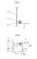
- the box 12a of the material holder is replaced by a plate 34 on which are erected, as described above, the clarinets or bayonets 13 and which, as in the previous embodiment , is equipped with axle devices 31 with which spring devices 32 are associated.
- the treatment fluid - introduced by the end piece 22 in the center of the tank 39 and in the bottom thereof - returns to the circulation circuit by several end pieces 23 also placed in the bottom of the tank or enclosure 39.
- these end fittings are provided below spaces 45 limited by the side wall of the tank 39, the bottom 18a, a vertical wall 46 internal to the erected tank.
- seals 38 with which is adapted to cooperate the underside of the plate 34 of the material carrier 1, while similar seals 36 are provided on the underside of rules 35 fixed on the single door (in the case of a device with a single opening for entry and exit) or on doors 20E and 20S of the device of FIGS. 6 and 7.
- the invention also prefers to provide the tank or enclosure with a vertical, flat partition in the vicinity of the closed rear part thereof, said wall allowing a connection from below between the front treatment part and the rear part of bath expansion, as described, for example, in US-A-4,581,906.
- the material carrier stocked at station B with coils 2 is introduced into the processing device 18 with a horizontal axis after the single door or the entry door 20E has been lifted (position shown in dashes in the drawing) and that have been brought into position, also shown in dashes, pivoting connecting rails 29E ensuring the continuity of the raceway between the rails 17 placed between the station B and the processing device 18 and the rails 17a of said processing apparatus.
- the material carrier lined with the reels is introduced into the processing device 18 by a pallet truck device or by sliding guide means, or also by transport members of the wire-guided type or the like.
- the clamping means 30 are actuated to cooperate with a central column 30a of the material carrier and make the sealed contact of the nozzle 22 for introducing the fluid. of treatment in the apparatus and of the nozzle 3 by which said fluid enters the box 12a of the material carrier 1.
- the spring devices 32 of the axle devices 31 are compressed by lowering of the box 12a of the material carrier, favoring the sealing of the circulation circuit of the treatment fluid.
- the level is, for example, adjusted to the value N l for a treatment of the "non-submerged" type, that is to say a treatment according to which the coil 2 of the coil stacks adjacent to the plate 12 is partially immersed or is not immersed at all, the free level of the bath, in the non-operating condition of the circulation pump, being below the level of the coils closest to the bottom of the enclosure of the processing device.
- the treatment bath is then circulated by means of the pump 24 to cause said bath to circulate from the inside to the outside of the coils, or from the outside to the inside or, again, in both directions, alternately.
- the flow rate of the latter can be adjusted for perfect control of the circulation of the treatment bath through wires, wicks and ribbons constituting the coils resulting in a better quality of the textile material treated due to the absence of abrupt variation of flow through the material windings.
- this arrangement makes it possible to carry out the treatment at low bath volume, of the order of 1/4, that is to say with substantial savings in water and calories provided by the heat exchanger. 25, treatment chemicals and / or releases.
- the means 30 are rendered inoperative, the spring devices 32 cause a slight upward movement of the box 12a, release the axle devices 31 and thereby interrupt the continuity of the circulation circuit of the fluid bath.
- the single door of the appliance or the exit door 20S of the appliance 18 with two doors is opened by being brought in its condition shown in dashes in the figure and, after connecting rails 29S have been brought by pivoting in the condition also shown in dashes in said figure, or that similar means for guiding the or material carriers have been put in place, said material carrier 1 is extracted from the device 18 and is guided by circulation on the rails 17 to the station D where it is unloaded.
- the loading and unloading time of a material carrier of an installation according to the invention is considerably reduced compared to that of known installations, the loading and / or unloading time of eight modules each comprising one hundred and twenty eight coils (32 stacks of 4 reels) being much less than the handling time one to one of one thousand twenty four reels (8x32x4).
- the introduction of the material holder 1 into the treatment apparatus 18 is similar to that described above, provided that when the means 30 are made operational to cooperate with the central column 30a of the material carrier, the downward movement of the plate 34, as shown by the arrow F in FIG. 8, causes the application of said plate on the seal means 38 while the closing of the door or doors 20 applies to sealing the seals 36 on the upper face of said plate.
- the pump 24 for circulating the bath is made operative to circulate the latter from the inside to the outside of the coils, or from the outside to inside, or alternately in one direction then in the other.
- the bath from the pump 24 through the central nozzle 22 enters the tank 39 under the plate 34 of the material carrier 1, crosses the coils 2 through the central orifice of the batteries and returns to the pump through orifices 40, spaces 45, and end pieces 23.
- the treatment can be carried out at atmospheric pressure or under static pressure of compressed air or inert gas and, here too, with a short or very short bath ratio, of the order of 1 / 4, significantly lower than that of installations known from the prior art (values of the order of 1/10 to 1/6).
- the invention also provides, in one and / or the other of the embodiments described above, to robotize the operation of the installation both as regards the loading and / or unloading of the modules 11 and in as regards the positioning and / or extraction of the material carrier 1 in the processing apparatus 18.
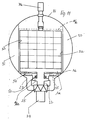
- the invention can, in particular, be implemented in an installation comprising a treatment device with a cylindrical horizontal external enclosure internally lined with vertical partition means defined by watertight boxes each having a parallelepiped shape.
- the invention can thus be implemented in an installation comprising a treatment device with an external enclosure with a horizontal axis provided inside with vertical walls formed by watertight boxes defining one or more parallelepiped volumes of reception of material carriers.
- This embodiment shown in Figures 10 and 11, is intended to receive two material carriers 1a, 1b each suitable for being provided with four modules of ten batteries each.
- the length of the enclosure is approximately 5 m. and the diameter of about 1.8 m., with the boxes 50 and 51 defining by their vertical walls 52 and 53 a substantially parallelepiped volume for the material carriers.
- the apparatus comprises the heat exchanger 25, a pump 24, advantageously of the reversible helical-centrifugal type and the guide means 54 and 55 for loading and unloading the material carrier (s) in the enclosure, said means being formed by rails, slides, traffic lanes or wire guidance devices.
- two clamping means 30a and 30b are provided in the cover 21.
- the treatment fluid passes through the parts treated by a circuit defined by openings in the bottom 18a of the external enclosure, said circuit comprising the end piece 22 connected to the pump 24 and the nozzles 23 also opening into the bottom 18a.
- the sealing means for establishing and ensuring the continuity of the treatment fluid circuit are shown at 60.
- the fluid level can be adjusted to N o for a treatment of the "non-submerged" type, that is to say with none of the coils at contact of the bath in the non-operating condition of the pump or at any level between N o and N 4 (level shown in dotted lines in Figure 11) and which is the one for which all the coils are immersed in the bath even in the non-operating condition of the pump 24.
- FIGS. 12 to 16 show an apparatus according to the invention for the treatment of shaped parts according to skeins of threads, fibers or similar textile materials.
- the material-holding device comprises a tank 110 with bottom 112 and lateral envelope 111 in which is formed an opening 113 which can be closed or released by a door 114, produced here as a vertically sliding door.
- a nozzle 115 for connecting and communicating the volume V parallelepiped inside the material carrier with the liquid or gaseous treatment fluid circuit of the machine for example by the nozzle 22 connected to the pump 24
- a first pair of members arranged horizontally in the condition of use of the device and one of the members of which is shown at 116, and a second pair of members substantially parallel to the first and of which one is shown at 117, in the vicinity of the bottom 112, while the first pair of members 116 is provided in the vicinity of the upper end of the envelope 111.
- the respective spacing of the pairs of members 116, 117 is adjustable, by means not shown, to adapt said spacing to the perimeter of the skeins E of threads, fibers, yarns or filaments to be treated.
- These skeins E are strung on bars B and C, the first of which support the skeins E and the second of which are designed to make them hang so that they do not become entangled in each other.
- the bars B are placed so as to overlap said members when the door 114 is open and the skeins are introduced into the material holder as shown by the direction of the arrow f in Figure 12.
- the bars B are placed as in the embodiment described immediately above, but the bars C are positioned under the members 117, here also when loading the material carrier in the condition of opening the door 114.
- the members 116, 117 may be constituted by rods or rails.
- the members 116 for supporting the bars B are rails and the members 117 are slides in which the bars or the like C are introduced and this so as to allow a slight withdrawal of the skeins E while preventing them from s' entwine each other.
- both the members 116 and the members 117 are constituted by parallel slides.
- the bars B for supporting the hanks rest alternately on one and the other of two first pairs of rods or rails 116a and 116b, offset in height relative to the bottom 112, allowing thus a greater loading density of the material carrier and a better homogeneity of treatment, the textile materials being at no point skeins clamped between two adjacent bars.
- the invention provides that the members arranged near the bottom 112 and with which the bars C cooperate are slides 117c and 117d offset in height in correspondence with the rails 116a and 116b.
- both the members 116 and the members 117 are slides offset in height relative to the bottom 112.
- the material carrier according to the invention is also provided with means intended to ensure a good distribution of the liquid or gaseous fluid for treating the materials to be treated and said means, for example in the form of grids, are arranged parallel to the bottom 112, the a 120 adjacent to said audit bottom and the other 121 in the upper part of the envelope.
- the external face of the lateral envelope 111 can be provided, in accordance with the invention, with dead bodies which, by reducing the space between the tank 110 and the interior of the wet treatment machine, make it possible to reduce the volume of bath used for the treatment of the material constituting the skeins E and, thus, to work with short or very short bath reports.
- the installation according to the invention considerably facilitates the skein handling operations by allowing the said skeins to be introduced in succession into a succession of machines without the need to load and unload the skeins in intermediate storage tanks, as previously required in installations using known material carriers.
- the useful length of the bars B corresponds to that of the arms of a mercerizing machine
- each of the arms of said machine is unloaded onto a bar B and, after said skeins have been provided, where appropriate, with bars C they are placed in the material carrier for the subsequent washing, bleaching, dyeing or other liquid treatment.
- FIG. 16 a treatment bath is put into circulation in an autoclave A with false bottom 123 pierced with an opening 130 provided at the upper end of a pipe 131 , while an opening 132 is suitable for being connected to a pipe 133, the latter and the pipe 131 being connected to a pump, not shown, located under the autoclave A to ensure the circulation of the treatment bath.
- the bath can flow in the direction from the opening 132 towards the piping 131, as shown by the arrows, or in the opposite direction.
- the false bottom 123 has an opening 135 formed substantially in the axis of the opening 132 and designed to receive a heat exchanger, not shown, housings 136 at the periphery of the false bottom being provided to receive internal pipes 137 which are made integral therewith.
- the circulation of the treatment fluid takes place through the nozzle 115 of the material carrier ensuring the communication of the volume V parallelepiped inside the material carrier with the circuit comprising the pipes 131, 133 and the pump, not shown, while that the grids or the like 120 and 121 ensure good distribution of the bath on the skeins of materials to be treated.
- the material carrier is extracted from autoclave A and is introduced into a drying apparatus. of the type described in European Patent Application No. 86400718 of April 3, 1986 in the name of the Applicant.
- a drying apparatus S comprises a tank 140 closed by a cover 141.
- the latter is provided with means 142 and a device 143 adapted to cooperate with a device 143 1 of a horizontal triangle resting on the upper face of the material carrier to establish and ensure the continuity of the treatment fluid circuit by forcibly applying, by tightening, the bottom 112 of the material carrier against seal means 145 provided at the end of a distribution box 146 in which pipes terminate 147 and 148 for the inlet and / or outlet of fluid into the material carrier, the outlet and / or inlet of fluid into the tank 140, respectively, being carried out using pipes 150 and 151 which open out in said tank.
- the treated or untreated air is introduced into the tank 140 through the pipe 150, enters the material carrier through the fluid distributor 121, as shown by the arrows g, leaves the carrier materials through the fluid distributor 120 and is discharged by the connecting means 115 of the material carrier with the rest of the drying apparatus.
Landscapes
- Engineering & Computer Science (AREA)
- Chemical & Material Sciences (AREA)
- Materials Engineering (AREA)
- Textile Engineering (AREA)
- Treatment Of Fiber Materials (AREA)
Applications Claiming Priority (4)
| Application Number | Priority Date | Filing Date | Title |
|---|---|---|---|
| FR8516990A FR2590286B1 (fr) | 1985-11-18 | 1985-11-18 | Procede et installation pour le traitement, a l'aide d'un fluide, de matieres textiles sur des porte-matieres |
| FR8516990 | 1985-11-18 | ||
| FR8518235 | 1985-12-10 | ||
| FR8518235A FR2591241B1 (fr) | 1985-12-10 | 1985-12-10 | Dispositif de porte-matieres pour machine ou installation de traitement liquide ou gazeux de matieres textiles fibreuses, poreuses ou en filaments |
Publications (2)
| Publication Number | Publication Date |
|---|---|
| EP0225246A1 true EP0225246A1 (de) | 1987-06-10 |
| EP0225246B1 EP0225246B1 (de) | 1991-05-29 |
Family
ID=26224825
Family Applications (1)
| Application Number | Title | Priority Date | Filing Date |
|---|---|---|---|
| EP86402543A Expired - Lifetime EP0225246B1 (de) | 1985-11-18 | 1986-11-17 | Verfahren und Vorrichtung zum Behandeln von textilen Materialien auf Materialträgern |
Country Status (4)
| Country | Link |
|---|---|
| US (1) | US4825668A (de) |
| EP (1) | EP0225246B1 (de) |
| DE (1) | DE3679515D1 (de) |
| ES (1) | ES2022138B3 (de) |
Cited By (5)
| Publication number | Priority date | Publication date | Assignee | Title |
|---|---|---|---|---|
| EP0276616A1 (de) * | 1986-12-30 | 1988-08-03 | M. P. DURAND & Cie | Vorrichtung zum Nassbehandeln von textilen Materialien auf Materialträgern |
| FR2612209A1 (fr) * | 1987-03-12 | 1988-09-16 | Barriquand | Perfectionnements aux installations de traitement au mouille de matieres textiles disposees sur des porte-matieres |
| EP0286509A1 (de) * | 1987-04-10 | 1988-10-12 | BARRIQUAND, Société dite: | Vorrichtung zur Nassveredlung von textilen Materialien |
| EP0288373A1 (de) * | 1987-04-22 | 1988-10-26 | M. P. DURAND & Cie | Vorrichtung zum automatischen Laden und/oder Entladen von Spulen |
| FR2620141A1 (fr) * | 1987-09-08 | 1989-03-10 | Barriquand | Machine de chargement et/ou de dechargement automatique de bobines de fil ou analogues sur un porte-matiere |
Families Citing this family (6)
| Publication number | Priority date | Publication date | Assignee | Title |
|---|---|---|---|---|
| US4995230A (en) * | 1987-10-19 | 1991-02-26 | Murata Kikai Kabushiki Kaisha | Steam setting system for spinning bobbin |
| US5495730A (en) * | 1993-04-19 | 1996-03-05 | Gaston County Dyeing Machine Company | Adapter for using a horizontal package dyeing carrier with a vertical treatment machine |
| US5442939A (en) * | 1993-04-19 | 1995-08-22 | Gaston County Dyeing Machine Co. | Carrier for supporting textile material in a wet treatment machine |
| US5410892A (en) * | 1993-04-19 | 1995-05-02 | Gaston County Dyeing Machine Company | Horizontal wet treatment machines for textiles and textile material carriers therefor |
| US5590553A (en) * | 1995-03-13 | 1997-01-07 | Gaston County Dyeing Machine Company | Carrier for supporting textile material packages in a wet treatment machine and package retaining cap for same |
| KR101226983B1 (ko) * | 2011-04-14 | 2013-02-06 | 한미타올 주식회사 | 소취사 제조 장치 및 그를 이용한 소취사 제조 방법 |
Citations (4)
| Publication number | Priority date | Publication date | Assignee | Title |
|---|---|---|---|---|
| FR1235717A (fr) * | 1959-08-01 | 1960-07-08 | Champagne Teinturerie | Machines à teindre |
| FR2003379A1 (de) * | 1968-03-07 | 1969-11-07 | Thies Spezialmaschinenfa | |
| US4341361A (en) * | 1980-10-01 | 1982-07-27 | Burke Mills, Inc. | Yarn carrier for pressure kier |
| EP0110058A1 (de) * | 1982-10-06 | 1984-06-13 | LORIS BELLINI & C. S.r.l. | Autoklav |
Family Cites Families (11)
| Publication number | Priority date | Publication date | Assignee | Title |
|---|---|---|---|---|
| US1052817A (en) * | 1909-07-28 | 1913-02-11 | John C Hebden | Dyeing apparatus. |
| FR501677A (fr) * | 1919-07-16 | 1920-04-21 | Octave Lecloux | Nouvelle machine à teindre la laine en bourre, en écheveaux, en bobines, ainsi que toutes autres matières pouvant etre empaquetées |
| BE424697A (de) * | 1936-11-25 | |||
| FR1037833A (fr) * | 1945-11-17 | 1953-09-23 | Machine à teindre les écheveaux | |
| US2944318A (en) * | 1958-01-28 | 1960-07-12 | Ohermaier & Cie | Material carrier for wet treatment of textiles |
| DE1460295A1 (de) * | 1964-07-04 | 1969-01-02 | Eugen Bellmann Gmbh Maschf | Textil-Faerbeanlage |
| DE1966527C3 (de) * | 1969-08-25 | 1979-08-09 | Croon & Lucke Maschinenfabrik Gmbh + Co Kg, 7947 Mengen | Vorrichtung zum Bedampfen von Garnsträngen |
| DE2129254A1 (de) * | 1971-06-12 | 1973-02-08 | Josef Jasper | Tragvorrichtung fuer garnspulen |
| DE2555974B2 (de) * | 1975-12-12 | 1978-11-30 | Jagri Maschinen- Und Apparatebau Gmbh, 4423 Gescher | Vorrichtung zum Färben von auf Spulen aufgewickeltem Material |
| JPS585301B2 (ja) * | 1978-05-30 | 1983-01-29 | ワイケイケイ株式会社 | ビ−ム液処理装置 |
| US4285216A (en) * | 1979-04-26 | 1981-08-25 | Polylok Corporation | Single bar, warp lift-off-resistant, lofted fabric construction |
-
1986
- 1986-11-17 EP EP86402543A patent/EP0225246B1/de not_active Expired - Lifetime
- 1986-11-17 ES ES86402543T patent/ES2022138B3/es not_active Expired - Lifetime
- 1986-11-17 DE DE8686402543T patent/DE3679515D1/de not_active Expired - Lifetime
- 1986-11-18 US US06/932,127 patent/US4825668A/en not_active Expired - Fee Related
Patent Citations (4)
| Publication number | Priority date | Publication date | Assignee | Title |
|---|---|---|---|---|
| FR1235717A (fr) * | 1959-08-01 | 1960-07-08 | Champagne Teinturerie | Machines à teindre |
| FR2003379A1 (de) * | 1968-03-07 | 1969-11-07 | Thies Spezialmaschinenfa | |
| US4341361A (en) * | 1980-10-01 | 1982-07-27 | Burke Mills, Inc. | Yarn carrier for pressure kier |
| EP0110058A1 (de) * | 1982-10-06 | 1984-06-13 | LORIS BELLINI & C. S.r.l. | Autoklav |
Cited By (8)
| Publication number | Priority date | Publication date | Assignee | Title |
|---|---|---|---|---|
| EP0276616A1 (de) * | 1986-12-30 | 1988-08-03 | M. P. DURAND & Cie | Vorrichtung zum Nassbehandeln von textilen Materialien auf Materialträgern |
| US4884418A (en) * | 1986-12-30 | 1989-12-05 | Barriquand | Installation for the wet treatment of textile materials disposed on material carriers |
| FR2612209A1 (fr) * | 1987-03-12 | 1988-09-16 | Barriquand | Perfectionnements aux installations de traitement au mouille de matieres textiles disposees sur des porte-matieres |
| EP0286509A1 (de) * | 1987-04-10 | 1988-10-12 | BARRIQUAND, Société dite: | Vorrichtung zur Nassveredlung von textilen Materialien |
| FR2613734A1 (fr) * | 1987-04-10 | 1988-10-14 | Barriquand | Machine de traitement au mouille de matieres textiles |
| EP0288373A1 (de) * | 1987-04-22 | 1988-10-26 | M. P. DURAND & Cie | Vorrichtung zum automatischen Laden und/oder Entladen von Spulen |
| FR2620141A1 (fr) * | 1987-09-08 | 1989-03-10 | Barriquand | Machine de chargement et/ou de dechargement automatique de bobines de fil ou analogues sur un porte-matiere |
| EP0307301A1 (de) * | 1987-09-08 | 1989-03-15 | M. P. DURAND & Cie | Vorrichtung zum automatischen Laden und/oder Entladen von Spulen |
Also Published As
| Publication number | Publication date |
|---|---|
| US4825668A (en) | 1989-05-02 |
| DE3679515D1 (de) | 1991-07-04 |
| ES2022138B3 (es) | 1991-12-01 |
| EP0225246B1 (de) | 1991-05-29 |
Similar Documents
| Publication | Publication Date | Title |
|---|---|---|
| EP0225246B1 (de) | Verfahren und Vorrichtung zum Behandeln von textilen Materialien auf Materialträgern | |
| EP0097066B1 (de) | Vorrichtung zur Entwässerung eines Garnwickels | |
| FR2620743A1 (fr) | Appareil de traitement thermique pour fuseaux de fil | |
| EP0276616B1 (de) | Vorrichtung zum Nassbehandeln von textilen Materialien auf Materialträgern | |
| CN100368622C (zh) | 用于卷绕在卷轴或者类似卷装上的纱线的染色或者漂白设备 | |
| FR2590286A1 (fr) | Procede et installation pour le traitement, a l'aide d'un fluide, de matieres textiles sur des porte-matieres | |
| FR2548223A1 (fr) | Dispositif de transport de bobines vides | |
| ITMI20001048A1 (it) | Macchina e impianto per la tintura di capi | |
| EP0060163B1 (de) | Vorrichtung zur Behandlung von textilen Materialien durch die Wirkung von Flüssigkeiten oder Gasen | |
| EP0208563A1 (de) | Verfahren und Vorrichtung zum Trocknen von Fasermaterial | |
| FR2591241A1 (fr) | Dispositif de porte-matieres pour machine ou installation de traitement liquide ou gazeux de matieres textiles fibreuses, poreuses ou en filaments | |
| EP0288373A1 (de) | Vorrichtung zum automatischen Laden und/oder Entladen von Spulen | |
| FR2576763A1 (fr) | Casier pour le stockage, la manutention et/ou la distribution de recipients cylindriques et dispositif pour permettre le chargement ou le dechargement desdits recipients destines a de tels casiers | |
| FR2609062A1 (fr) | Autoclave perfectionne, notamment pour le traitement au mouille de matieres textiles | |
| EP0286509A1 (de) | Vorrichtung zur Nassveredlung von textilen Materialien | |
| US5495730A (en) | Adapter for using a horizontal package dyeing carrier with a vertical treatment machine | |
| FR2610016A1 (fr) | Installation perfectionnee de traitement au mouille de matieres textiles disposees sur des porte-matieres | |
| CA1155147A (fr) | Procede et dispositif de manutention de produits longs, notamment de tubes | |
| FR2488719A1 (fr) | Installation et procede de manutention des assemblages d'un reacteur nucleaire a neutrons rapides | |
| FR2614324A1 (fr) | Procede de traitement de bobines de fils ou analogues et machine pour sa mise en oeuvre. | |
| EP0134180A1 (de) | Vorrichtung zum Zentrifugieren von textilen Wickeln | |
| EP0135450B1 (de) | Horizontaler Autoklav für die Nassbehandlung von Textil-Materialien | |
| BE891905Q (fr) | Cuve de teinturerie comportant un panier grillage pouvant etre retire en vue du transfert rapide des articles traites. | |
| FR2577250A1 (fr) | Procede de sechage en continu de fils textiles et machine pour la mise en oeuvre de ce procede | |
| FR2486974A1 (fr) | Perfectionnements aux porte-bobinots de teinture |
Legal Events
| Date | Code | Title | Description |
|---|---|---|---|
| PUAI | Public reference made under article 153(3) epc to a published international application that has entered the european phase |
Free format text: ORIGINAL CODE: 0009012 |
|
| AK | Designated contracting states |
Kind code of ref document: A1 Designated state(s): BE CH DE ES FR GB IT LI LU |
|
| 17P | Request for examination filed |
Effective date: 19871130 |
|
| 17Q | First examination report despatched |
Effective date: 19890421 |
|
| GRAA | (expected) grant |
Free format text: ORIGINAL CODE: 0009210 |
|
| AK | Designated contracting states |
Kind code of ref document: B1 Designated state(s): BE CH DE ES FR GB IT LI LU |
|
| ITF | It: translation for a ep patent filed | ||
| GBT | Gb: translation of ep patent filed (gb section 77(6)(a)/1977) | ||
| REF | Corresponds to: |
Ref document number: 3679515 Country of ref document: DE Date of ref document: 19910704 |
|
| PG25 | Lapsed in a contracting state [announced via postgrant information from national office to epo] |
Ref country code: GB Effective date: 19911117 |
|
| PG25 | Lapsed in a contracting state [announced via postgrant information from national office to epo] |
Ref country code: ES Free format text: LAPSE BECAUSE OF THE APPLICANT RENOUNCES Effective date: 19911118 |
|
| PG25 | Lapsed in a contracting state [announced via postgrant information from national office to epo] |
Ref country code: LU Free format text: LAPSE BECAUSE OF NON-PAYMENT OF DUE FEES Effective date: 19911130 Ref country code: LI Effective date: 19911130 Ref country code: CH Effective date: 19911130 Ref country code: BE Effective date: 19911130 |
|
| PLBE | No opposition filed within time limit |
Free format text: ORIGINAL CODE: 0009261 |
|
| STAA | Information on the status of an ep patent application or granted ep patent |
Free format text: STATUS: NO OPPOSITION FILED WITHIN TIME LIMIT |
|
| 26N | No opposition filed | ||
| BERE | Be: lapsed |
Owner name: BARRIQUAND Effective date: 19911130 |
|
| GBPC | Gb: european patent ceased through non-payment of renewal fee | ||
| PG25 | Lapsed in a contracting state [announced via postgrant information from national office to epo] |
Ref country code: FR Effective date: 19920731 |
|
| REG | Reference to a national code |
Ref country code: CH Ref legal event code: PL |
|
| PG25 | Lapsed in a contracting state [announced via postgrant information from national office to epo] |
Ref country code: DE Effective date: 19920801 |
|
| REG | Reference to a national code |
Ref country code: FR Ref legal event code: ST |
|
| REG | Reference to a national code |
Ref country code: ES Ref legal event code: FD2A Effective date: 20010402 |
|
| PG25 | Lapsed in a contracting state [announced via postgrant information from national office to epo] |
Ref country code: IT Free format text: LAPSE BECAUSE OF NON-PAYMENT OF DUE FEES;WARNING: LAPSES OF ITALIAN PATENTS WITH EFFECTIVE DATE BEFORE 2007 MAY HAVE OCCURRED AT ANY TIME BEFORE 2007. THE CORRECT EFFECTIVE DATE MAY BE DIFFERENT FROM THE ONE RECORDED. Effective date: 20051117 |