EP0225258A2 - Steuersystem für einen Fokus-Servomechanismus eines optischen Plattensystems mit P-Abweichungseinstellung - Google Patents
Steuersystem für einen Fokus-Servomechanismus eines optischen Plattensystems mit P-Abweichungseinstellung Download PDFInfo
- Publication number
- EP0225258A2 EP0225258A2 EP86402632A EP86402632A EP0225258A2 EP 0225258 A2 EP0225258 A2 EP 0225258A2 EP 86402632 A EP86402632 A EP 86402632A EP 86402632 A EP86402632 A EP 86402632A EP 0225258 A2 EP0225258 A2 EP 0225258A2
- Authority
- EP
- European Patent Office
- Prior art keywords
- offset
- focus
- error signal
- control system
- offset parameter
- Prior art date
- Legal status (The legal status is an assumption and is not a legal conclusion. Google has not performed a legal analysis and makes no representation as to the accuracy of the status listed.)
- Granted
Links
Images








Classifications
-
- G—PHYSICS
- G11—INFORMATION STORAGE
- G11B—INFORMATION STORAGE BASED ON RELATIVE MOVEMENT BETWEEN RECORD CARRIER AND TRANSDUCER
- G11B7/00—Recording or reproducing by optical means, e.g. recording using a thermal beam of optical radiation by modifying optical properties or the physical structure, reproducing using an optical beam at lower power by sensing optical properties; Record carriers therefor
- G11B7/08—Disposition or mounting of heads or light sources relatively to record carriers
- G11B7/09—Disposition or mounting of heads or light sources relatively to record carriers with provision for moving the light beam or focus plane for the purpose of maintaining alignment of the light beam relative to the record carrier during transducing operation, e.g. to compensate for surface irregularities of the latter or for track following
-
- G—PHYSICS
- G11—INFORMATION STORAGE
- G11B—INFORMATION STORAGE BASED ON RELATIVE MOVEMENT BETWEEN RECORD CARRIER AND TRANSDUCER
- G11B7/00—Recording or reproducing by optical means, e.g. recording using a thermal beam of optical radiation by modifying optical properties or the physical structure, reproducing using an optical beam at lower power by sensing optical properties; Record carriers therefor
- G11B7/08—Disposition or mounting of heads or light sources relatively to record carriers
- G11B7/085—Disposition or mounting of heads or light sources relatively to record carriers with provision for moving the light beam into, or out of, its operative position or across tracks, otherwise than during the transducing operation, e.g. for adjustment or preliminary positioning or track change or selection
- G11B7/08505—Methods for track change, selection or preliminary positioning by moving the head
- G11B7/08517—Methods for track change, selection or preliminary positioning by moving the head with tracking pull-in only
-
- G—PHYSICS
- G11—INFORMATION STORAGE
- G11B—INFORMATION STORAGE BASED ON RELATIVE MOVEMENT BETWEEN RECORD CARRIER AND TRANSDUCER
- G11B7/00—Recording or reproducing by optical means, e.g. recording using a thermal beam of optical radiation by modifying optical properties or the physical structure, reproducing using an optical beam at lower power by sensing optical properties; Record carriers therefor
- G11B7/08—Disposition or mounting of heads or light sources relatively to record carriers
- G11B7/09—Disposition or mounting of heads or light sources relatively to record carriers with provision for moving the light beam or focus plane for the purpose of maintaining alignment of the light beam relative to the record carrier during transducing operation, e.g. to compensate for surface irregularities of the latter or for track following
- G11B7/094—Methods and circuits for servo offset compensation
-
- G—PHYSICS
- G11—INFORMATION STORAGE
- G11B—INFORMATION STORAGE BASED ON RELATIVE MOVEMENT BETWEEN RECORD CARRIER AND TRANSDUCER
- G11B7/00—Recording or reproducing by optical means, e.g. recording using a thermal beam of optical radiation by modifying optical properties or the physical structure, reproducing using an optical beam at lower power by sensing optical properties; Record carriers therefor
- G11B7/08—Disposition or mounting of heads or light sources relatively to record carriers
- G11B7/09—Disposition or mounting of heads or light sources relatively to record carriers with provision for moving the light beam or focus plane for the purpose of maintaining alignment of the light beam relative to the record carrier during transducing operation, e.g. to compensate for surface irregularities of the latter or for track following
- G11B7/0908—Disposition or mounting of heads or light sources relatively to record carriers with provision for moving the light beam or focus plane for the purpose of maintaining alignment of the light beam relative to the record carrier during transducing operation, e.g. to compensate for surface irregularities of the latter or for track following for focusing only
- G11B7/0917—Focus-error methods other than those covered by G11B7/0909 - G11B7/0916
- G11B2007/0919—Critical angle methods
Definitions
- the present invention relates to a focus servomechanism control system for controlling a focus of light beams impinging on a recording film of an optical disc in an optical disc system. More particularly, it relates to a focus servomechanism control system having an automatic offset setting means for automatically determining an optimum offset value which generates an optimum focus of light beams impinging on the recording film, and setting the determined optimum offset value to a light beam focusing means.
- An optical disc system used as a large-capacity external memory device in an information processing system can record at a density more than ten times that of the recording density attainable by a conventional magnetic disc system.
- Data recording in the optical disc system is accomplished, for example, by applying strong light beams, i.e., at a write power level, from a laser diode to tracks defined in a recording film on an optical disc to form holes or pits in the tracks in the recording film by thermal reaction.
- the data thus written in the tracks in the recording film can be read form reflected beams when weak laser beams emitted from the laser diode are applied as optical beams having a read power level lower than the write power level to the tracks.
- the tracks are defined with a small distance between adjacent tracks, for example, several micron meters, in a radial direction of the optical disc.
- a track servomechanism control system is provided to precisely control the positioning of an optical head emitting laser beams and receiving the reflected beams with a corresponding track.
- a focus servomechanism control system is provided to precisely control the focusing of laser beams emitted from the optical head onto the tracks to ensure data recording on and data reproduction from the optical disc.
- offsetting becomes necessary due to, for example, the displacement of a light sensing element, and inner circuits in the focus servomechanism.
- an offset compensation must be provided to improve the accuracy of the data recording and reproduction.
- a tracking servomechanism signal more specifically, a tracking error signal, is used for determining the focus.
- a preformat is recorded in each track, and a light measurement circuit receives the preformat signal, detects a deviation between a light beam axis and the track, and produces the tracking error signal. It is considered that the optimum focus is obtained when the tracking error signal is at a maximum amplitude.
- the detection of the optimum focus is performed manually, for example, by changing a variable resistor for a focus offset adjustment, observing the tracking error signal on an oscilloscope, determining a value of the variable resistor which produces the maximum amplitude of the tracking error signal, and finally, locking the variable resistor by using an adherent such as paint.
- the prior art offset adjustment suffers from the disadvantages of a low accuracy for the optimum offset value, a low operation efficiency, and a lack of flexibility for readjustment when the offset is varied after an initial offset adjustment has been performed.
- An object of the present invention is to provide a focus servomechanism system for an optical disc system having an automatic offset adjustment means.
- Another object of the present invention is to provide a focus servomechanism system for an optical disc system having an automatic offset adjustment means which can adjust an offset to an optimum offset.
- a focus servomechanism control system in an optical disc system including a rotatable optical disc having at least one track storing data therein, a unit for focusing light for data write and read on the track, and a unit for sensing light reflected from the track and controlling the light focusing unit to adjust the focus of the light on the track.
- the focus servomechanism control system includes a unit, operatively connected to the light focusing unit, for moving the light focusing unit in a direction perpendicular to a plane of the optical disc; a unit, operatively connected to the light sensing unit, for producing a focus error signal; a unit, operatively connected to the light sensing unit, for producing a track error signal; and a unit, operatively connected to the focus error signal producing unit and receiving an offset parameter, for controlling a position of the light focusing unit through the light focusing unit moving unit in response to the focus error signal and the offset parameter.
- the focus servomechanism control system further includes an offset setting unit, operatively connected to the position control unit and the track error signal producing unit, during an offset adjustment mode, for continuously setting a plurality of offset parameters to the position control unit, to determine a maximum amplitude of the track error signal, and to set the offset parameter producing the maximum amplitude of the track error signal to the position control unit.
- an offset setting unit operatively connected to the position control unit and the track error signal producing unit, during an offset adjustment mode, for continuously setting a plurality of offset parameters to the position control unit, to determine a maximum amplitude of the track error signal, and to set the offset parameter producing the maximum amplitude of the track error signal to the position control unit.
- the offset setting unit may include a processor; a largest amplitude detection circuit, operatively connected between the track error signal producing unit and the processor, for detecting a largest amplitude of the track error signal and for sending the largest amplitude to the processor; and an offset outputting circuit, operatively connected between the position control unit and the processor, for outputting the offset parameter from the processor to the position control unit.
- the processor continuously outputs the plurality of offset parameters, receives the largest amplitude from the amplitude detection circuit for each offset parameter, determines a maximum amplitude from among the received largest amplitudes, and sets the offset parameter producing the maximum amplitude.
- the amplitude detection circuit may include a sample holder and an analog-to-digital (A/D) converter connected thereto.
- the processor outputs a sample hold signal to the sample holder in a short period shorter than a frequency of the tracking error signal, to hold the tracking error signal for another short time sufficient for A/D conversion in the sample holder.
- the A/D converter operates in response to the sample hold signal.
- the offset outputting circuit may include a digital-to-analog (D/A) converter outputting an analog signal corresponding to the offset parameter.
- the offset outputting circuit may also include a plurality of resistors and a plurality of switches selectively shorting the resistors to change a total resistance of the resistors.
- the processor selectively energizes the switches in response to the offset parameter, and the offset outputting circuit substantially changes a signal used for controlling the position of the light focusing unit in response to the offset parameter and the focus error signal.
- the amplitude detection circuit may include a peak holder and an analog-to-digital (A/D) converter connected thereto.
- the processor energizes the A/D converter before the output of a next offset parameter, receives an A/D converted value in response to the completion of an A/D conversion, and resets the peak holder.
- the amplitude detection circuit may also include an envelope detection type amplitude detection circuit, an integrator integrating the detected signal at the amplitude detection circuit, and an analog-to-digital (A/D) converter connected to the integrator.
- the processor energizes the A/D converter before the output of a next offset parameter, receives an A/D converted value in response to the completion of an A/D conversion, and resets the integrator.
- the offset setting unit continuously sets the plurality of offset parameters in response to each rotation of the optical disc.
- the optical disc system includes an optical disc 1 having a recording film with a plurality of tracks defined therein, a rotatable shaft 1b, and a rotating mechanism 1a, for example a motor.
- the rotating mechanism 1a rotates at a rated speed to rotate the rotatable shaft 1b, resulting in a rotation of the optical disc 1.
- the optical disc system also includes an optical head 2, a moving mechanism 3 having the optical head 2 mounted thereon, a focus servomechanism control unit 4, and a tracking servomechanism control unit 5.
- the optical head 2 includes a semiconductor laser 20 as a light source, a collimator lens 21a, a beam splitter 22, a quarter wave plate 23, a mirror 24a, and an objective lens 25.
- a first optical system consisting of the above optical elements provides light beams focused onto a track in the optical disc 1, to carry out a data write to and read from the optical disc 1.
- the optical head 2 also includes a half transparent mirror 24b, a lens 21b, and a first light sensing device 28.
- the optical head 2 further includes a critical-angle prism 29a and a second light sensing device 29.
- a third optical system consisting of the lens 25, the mirror 24a, the quarter wave plate 23, the beam splitter 22, the half transparent mirror 24b, the prism 29a, and the light sensing device 29, provides a tracking error signal TES, which will be used for adjusting an offset, and a focus error signal FES.
- the optical head 2 includes a focus actuator 27 operatively connected to the lens 25 for moving the lens 25 in a direction perpendicular to a plane of the optical disc 1, to change the focusing position of the lens 25 relative to the tracks of the optical disc 1.
- the optical head 2 further includes a track actuator 26 also operatively connected to the lens 25 for moving the lens 25 in a direction parallel to a plane of the optical disc 1, i.e., in a direction crossing the tracks in the optical disc 1.
- the production of the focus error signal FES will be described with reference to Figs. 2a to 2e.
- the light sensing device 29 is divided into four sensing portions a , b , c and d , as shown in Figs. 2b to 2d.
- the distribution of the light reflected to the sensing portions a to d is even, as shown in Fig. 2c.
- light reflected to the sensing portions c and d is stronger than those at the sensing portions a and b , as shown in Fig.
- the focus servomechanism control unit 4 activates the focus actuator 27 in the optical head 2 in response to the focus error signal FES, to focus the light beams from the lens 25 at the in-focus point f on the track.
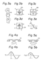
- the generation of the track error signal TES will be described with reference to Figs. 3a to 3e.
- Light beams from the lens 25 can be subjected to light interference in response to a point in the track 10.
- the distribution of reflected light received at the sensing portions a to d of the light sensing element 29 is even, as shown in Fig. 3c.
- the light beams are shifted leftwards from the center point p and directed onto a left side point p1 , the reflected light received at the sensing portions b and c stronger than that received at the sensing portions a and d , as shown in Fig.
- a track error signal TES (La + Ld) - (Lb + Lc) ... (2)
- the tracking servomechanism control unit 5 activates the track actuator 26 in the optical head 2 in response to the track error signal TES to move the lens 25 in a horizontal direction so as to direct the light beams onto the center point p in Fig. 3a.
- an amplitude w1 of the track error signal TES in Fig. 4b is higher than an amplitude w2 in Fig. 5b when the light beams from the lens 25 are shifted as shown in Fig. 5a.
- an optimum offset value can be determined by detecting a maximum amplitude of the track error signal TES.
- a focus servomechanism control system of a first embodiment of the present invention will be described with reference to Figs. 6 to 11.
- a focus servomechanism control unit 4 includes input resistors R1 to R4 receiving electrical signals La to Ld from the sensing portions a to d of the light sensing element 29, an operational amplifier 40 functioning as a subtracting circuit for producing the focus error signal FES in accordance with the formula (1), and an operational amplifier 42 functioning as an adder for adding an offset value OS described later to the focus error signal FES.
- the added focus error signal is amplified at a power amplifier 41, and the amplified signal is then supplied to the focus actuator 27 in the optical head 2 in Fig. 1.
- references R9, R10, R11, R12, and R15 represent resistors.
- a tracking servomechanism control unit 5 includes input resistors R5 to R8 receiving the electrical signals La to Ld, an operational amplifier 50 functioning as a subtracting circuit for producing the track error signal TES in accordance with the formula (2), a power amplifier 51, a switch 52, and resistors R5, R13 and R14. An amplified signal at the power amplifier 51 is supplied to the track actuator 26 in the optical head 2 in Fig. 1 through the switch 52.
- the focus servomechanism control system further includes an offset adjustment block including a microprocessor unit (MPU) 60, a digital-to-analog (D/A) converter 63, a sample holder 65, and an analog-to-digital (A/D) converter 62 in addition to the above servomechanism control units 4 and 5.
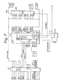
- the MPU 60 per se , has a conventional structure as shown in Fig. 7.
- the MPU 60 includes, for example, a data bus buffer DBB, an address bus buffer ABB, an A register, a B register, an arithmetic and logic unit ALU, an instruction register I, an input/output interface, and a control circuit CONT.
- the microprocessor 92 used may be, for example, an INTEL 8031.
- the ROM 93 stores a plurality of offset data for determining a maximum offset value and programs for the following operation.
- the oscillator 94 generates a clock signal CLK which is applied to the control circuit CONT in the microprocessor 92.
- the MPU 60 outputs a lock signal LOCK to the switch 52 in the tracking servomechanism control unit 5 to substantially deenergize the tracking servomechanism control during the offset adjustment operation.
- the MPU 60 sequentially outputs the offset data to the D/A converter 63 to determine the maximum offset value.
- the D/A converter 63 produces the offset value OS in accordance with commands and data from the MPU 60.
- the MPU 60 periodically outputs a sampling signal SAMPLE to the sample holder 65, to hold the track error signal TES for a short time to stabilize the A/D conversion data.
- the sample holder 65 holds the track error signal TES from the amplifier 50, and the A/D converter 62 converts data held at the sample holder 63 into a digital value.
- the digital-converted track error signal TESd is input to the MPU 60.
- Steps 001 to 003 (S001 to S003)
- the MPU 60 When power is supplied to the MPU 60 and a power ON signal PWRON is received at the MPU 60, the MPU 60 starts an offset adjustment operation. Namely, at step 001, the MPU 60 outputs a lock signal LOCK to the switch 52 in the tracking servomechanism control unit 5 to substantially deenergize the tracking servomechanism control. Then, at step 002, the MPU 60 turns ON the focus servomechanism control unit 4, and at step 003, the MPU 60 clears a maximum peak value stored therein.
- the MPU 60 waits until a home position signal HOMEPSTN is input herein.
- This home position signal HOMEPSTN is output from an optical disc mechanism at each rotation of the optical disc 1.
- the MPU 60 then updates the offset value in response to the home position signal HOMEPSTN.
- the MPU 60 Upon receipt of the home position signal HOMEPSTN, at step 005, the MPU 60 clears a peak data stored therein. Then, at step 006, the MPU 60 outputs a first offset data OS0 , which may be zero, stored in the ROM 93 and shown in Fig. 9a, to the D/A converter 63.
- the D/A converter 63 provides an offset value of the analog value, i.e., a voltage signal, to the amplifier 42 in the focus servomechanism control unit 4 through the resistor R10.
- the amplifier 42 adds the offset value OS to the focus error signal FES, and the focus actuator 27 moves the lens 25 in response to the added FES and OS control signal.
- the track error signal TES for the offset value OS can be produced from the amplifier 50 in the tracking servomechanism control unit 5, as shown in Fig. 9b.
- the MPU 60 outputs a sampling signal SAMPLE to the sample holder 65, and starts the A/D converter 62.
- the sample signal SAMPLE can be periodically output in a period shorter than a period of the tracking error signal and sufficient short to detect a peak value of the tracking signal.
- a sample held track error data from the amplifier 50 can be converted into a digital track error signal TESd at the A/D converter 62.
- the MPU 60 reads the track error signal TESd, and at step 009, the MPU 60 compares the current track error signal TESd and the peak data.
- the MPU 60 updates the peak data to the current track error signal TESd, and at step 011, saves the current offset value. If the result at step 009 is NO, the MPU 60 by-passes these operations.
- Figure 10 is an enlarged wave form graph of the track error signal TES in Fig. 9b.
- the track error signal TES oscillates at a frequency defined by the rotation of the optical disc 1.
- a plurality of bars represent timings of the sampling and the A/D conversion.
- a maximum peak value of the track error signal TES can be detected for one offset value OS.
- the MPU 60 compares the maximum peak value therein and a new maximum peak value obtained through the above operations of steps S007 to S012. When the new maximum peak value is greater than the previous maximum peak value, at step 013, then at step 014, the MPU 60 updates the maximum peak value to the new maximum peak value, and at step 015, saves the offset value producing the new maximum peak value. If the result is NO at step 013, the updating operation is by-passed by the MPU 60.
- Steps 016 and 017 (S016 and S017)
- step 016 the output for all offset data shown in Fig. 9a is not yet completed, then at step 017, the MPU 60 updates the offset data to the next value stored in the ROM 93 and repeats the operations from step 005.
- Steps 016 and 018 (S016 and S018)
- the maximum peak value stored in the MPU 60 indicates a maximum amplitude of the track error signal TES from among a plurality of maximum amplitudes of the track error signals TES obtained for the plurality of offset values as shown in Fig. 11.
- the maximum amplitude is regarded as an optimum offset value.
- the MPU 60 sets the offset value producing the maximum amplitude to the D/A converter 63 as an optimum offset value, to focus the light beams at the in-focus point f on the track of the optical disc 1.
- the MPU 60 then releases the lock on the tracking servomechanism control by outputting the an ON state lock signal LOCK, and thus terminates the offset adjustment operation.
- the optimum offset value is automatically determined from the above operation.
- the focus servomechanism control is effected in response to the offset value OS having a constant value obtained by the above operation and the focus error signal FES produced at the amplifier 40.
- an offset setting circuit 45 consisting of series-connected resistors R25 to R28 and switches SW1 to SW4 is provided.
- the resistance values of the series-connected resistors R25 to R28 are weighed by, for example, 1, 2, 4, 8, and a resistance value of the series-connected resistors R25 to R28 is varied between zero and 15 by changing the status of the switches SW1 to SW4.
- the series-connected resistors R25 to R28 act as a feedback resistor for an amplifier 40a together with a resistor R29, and the amplifier 40a first calculates the following formula: ⁇ (Lc + Ld) where, ⁇ is an amplification factor defined by the offset setting circuit 45.
- an amplifier 40b produces a signal (La + Lb), and the amplifier 42 calculates a value ⁇ (Lc + Ld) - (La +Lb).
- the calculated value is substantially equal to the value (FES + OS) output from the amplifier 42 in Fig. 6.
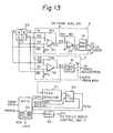
- an offset adjustment system includes a peak detector 61 instead of the sample holder 65 shown in Figs. 6 and 11.
- Other circuits shown in Fig. 13 are substantially identical to those in Fig. 6.
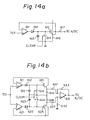
- the peak detector 61 may be a conventional peak detector, as shown in Figs. 14a and 14b.
- the peak detector shown in Fig. 14a includes an amplifier 611, a diode 612, a capacitor 613, a reset switch 614, a transistor 615, and resistors 616 and 617.
- the peak detector detects a peak having a positive polarity.
- the peak detector holds that peak and clears the held peak by supplying a clear signal CLEAR from the MPU 60b.
- the peak detector shown in Fig. 14b includes a positive peak detection circuit including the elements 611 to 617 and having a same circuit construction as shown in Fig. 14a, a negative peak detection circuit including the elements 612 to 627, and a subtraction circuit including an amplifier 631 and resistors 632 and 633.
- the peak detector shown in Fig. 14b provides a peak-to-peak value.
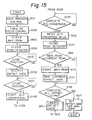
- FIG. 15 is a flow chart
- Figs. 16a to 16g are timing charts.
- Steps 101 to 104 (S101 to S104)
- Steps S101 to S103 in Fig. 15a are substantially equal to steps S001 to S003 in Fig. 8a, and thus a description thereof is omitted.
- the MPU 60b outputs a clear signal CLEAR to the peak detector 61, to reset the peak value held therein.
- Steps 105 and 106 (S105 and S106)
- the MPU 60b Upon receipt the home position signal HOMEPSTN (Fig. 16a) at step 105, the MPU 60b outputs a first offset value stored in the ROM 93 through the D/A converter 63 to the focus servomechanism control unit 4 (Fig. 16g) at step 106.
- the MPU 60b waits until the home position signal HOMEPSTN is supplied.
- the peak detector 61 detects the peak of the tracking error signal TES, as shown in Fig. 16b, and updates a maximum peak for the offset value (Fig. 16c).
- Steps 108 to 111 (S108 to S111)
- the MPU 60b Upon receipt of the home position signal HOMEPSTN at step 107, the MPU 60b outputs an A/D conversion start signal ADCSTART to the A/D converter 62 to start the A/D conversion for the peak data (Fig. 16d) at step 108.
- the A/D converter 62 Upon completion of the A/D conversion at step 109, the A/D converter 62 sends an A/D conversion end signal ADCEND to the MPU 60b (Fig. 16e) at step 110, the MPU 60b reads an A/D converted peak value TESd, and then at step 111, clears the peak detector 61.
- Steps 112 to 117 (S112 to S117)
- steps S112 to S117 are substantially the same as those of steps S013 to S018 shown in Fig. 8b, and thus a description thereof is omitted.
- the load at the MPU 60b is greatly reduced, because the high speed sampling control between steps S007 and S012 in Fig. 8a is removed. Therefore, in the focus servomechanism control system shown in Fig. 13, and A/D converter 62 of a low A/D conversion time can be used. In particular, by introducing the peak detector 61, the peak-detection accuracy can be improved.
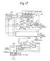
- the focus servomechanism control system in Fig. 17 is combined with the focus servomechanism control system shown in Fig. 13 and the focus servomechanism control system shown in Fig. 12. That is, the D/A converter 63 in Fig. 13 is omitted, and the focus servomechanism control unit 4a has the same arrangement as that of Fig. 12. A detailed circuit of the tracking servomechanism control unit 5 is not illustrated, but has a same arrangement as that of Fig. 13. Accordingly, a description of the operation of the focus servomechanism control system in Fig. 17 is omitted.
- the focus servomechanism control system shown in Fig. 18 has an arrangement similar to that of Fig. 13, except that an envelope detection type peak detector and integrator 64 is provided instead of the peak detector 61 in Fig. 13.
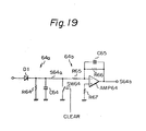
- the envelope detection type peak detection and integrator 64 can be used as a conventional circuit as shown in Fig. 19.
- the envelope detection type peak detection and integrator 64 includes an envelope detection peak circuit 64a consisting of a diode D1, a resistor R64 and a capacitor C64, and an integrator circuit 64b consisting of an amplifier AMP64, resistors R65, R66 and R67, a capacitor C65, and a reset switch SW64.
- the tracking error signal TES oscillates at a high frequency defined by the rotation speed of the optical disk 1, and accordingly, the envelope detection peak circuit 64 accurately detects a peak value of the enveloped tracking error signal TES, as shown by a dotted line (Fig. 20c).
- the detected peak value is stably held at the integrator circuit 64b during the A/D conversion.
- the accuracy of the A/D converted peak value is improved because any change of the peak value held in the integrator circuit 64b can be substantially neglected.
- a focus servomechanism control system in Fig. 21 is combined with the focus servomechanism control system shown in Fig. 18 and the focus servomechanism control system shown in Fig. 12. Accordingly, a description of the operation of the focus servomechanism control system in Fig. 21 is omitted.
Landscapes
- Optical Recording Or Reproduction (AREA)
Applications Claiming Priority (4)
| Application Number | Priority Date | Filing Date | Title |
|---|---|---|---|
| JP267679/85 | 1985-11-28 | ||
| JP60267679A JPS62128027A (ja) | 1985-11-28 | 1985-11-28 | 光デイスクのフオ−カスサ−ボ方式 |
| JP53241/86 | 1986-03-11 | ||
| JP61053241A JPS62222438A (ja) | 1986-03-11 | 1986-03-11 | フオ−カスサ−ボ制御系のオフセツト自動調整方法 |
Publications (3)
| Publication Number | Publication Date |
|---|---|
| EP0225258A2 true EP0225258A2 (de) | 1987-06-10 |
| EP0225258A3 EP0225258A3 (en) | 1989-08-16 |
| EP0225258B1 EP0225258B1 (de) | 1991-07-17 |
Family
ID=26393957
Family Applications (1)
| Application Number | Title | Priority Date | Filing Date |
|---|---|---|---|
| EP86402632A Expired - Lifetime EP0225258B1 (de) | 1985-11-28 | 1986-11-27 | Steuersystem für einen Fokus-Servomechanismus eines optischen Plattensystems mit P-Abweichungseinstellung |
Country Status (6)
| Country | Link |
|---|---|
| US (1) | US4707648A (de) |
| EP (1) | EP0225258B1 (de) |
| KR (1) | KR900008770B1 (de) |
| AU (1) | AU569437B2 (de) |
| CA (1) | CA1261467A (de) |
| DE (1) | DE3680300D1 (de) |
Cited By (6)
| Publication number | Priority date | Publication date | Assignee | Title |
|---|---|---|---|---|
| EP0270365A1 (de) * | 1986-12-05 | 1988-06-08 | Sony Corporation | Gerät mit Servostromkreisen zur Aufzeichnung und/oder Wiedergabe von optischen Platten |
| EP0309719A1 (de) * | 1987-09-30 | 1989-04-05 | Deutsche Thomson-Brandt GmbH | Gerät zur Wiedergabe von Daten |
| EP0349439A3 (de) * | 1988-06-29 | 1991-05-02 | Fujitsu Limited | System zur Ermittlung des optimalen Brennpunkts eines optischen Plattensystems |
| EP0425042A1 (de) * | 1989-10-25 | 1991-05-02 | Koninklijke Philips Electronics N.V. | Verfahren und Anordnung zum Detektieren von Parametern eines digital steuerbaren Prozesskreises zum Steuern der Abtastung eines Datenträgers |
| EP0304932A3 (de) * | 1987-08-28 | 1991-09-11 | Fujitsu Limited | Zugriffssystem für optische Platten |
| US5136568A (en) * | 1986-12-15 | 1992-08-04 | Deutsche Thomson-Brandt Gmbh | Tracking circuit for guiding a beam of light along data tracks of a recorded medium |
Families Citing this family (34)
| Publication number | Priority date | Publication date | Assignee | Title |
|---|---|---|---|---|
| US4878211A (en) * | 1986-05-26 | 1989-10-31 | Pioneer Electronic Corporation | Method and apparatus for correcting the loop gain of a servo loop in accordance with measurements during open-loop operation |
| JPH0760527B2 (ja) * | 1986-09-17 | 1995-06-28 | パイオニア株式会社 | 光学式ピックアップ装置 |
| US4998234A (en) * | 1987-03-31 | 1991-03-05 | Rees Theodore D | Logarithmic servo error detection for optical disk drive |
| JPH01204234A (ja) * | 1988-02-08 | 1989-08-16 | Canon Inc | 光学的情報記録再生装置 |
| DE3824039A1 (de) * | 1988-07-15 | 1990-01-18 | Thomson Brandt Gmbh | Verfahren und schaltungsanordnung zur kompensation von offset-spannungen in einem fokus- und/oder spurregelkreis |
| EP0354754B1 (de) * | 1988-08-09 | 1994-03-09 | Matsushita Electric Industrial Co., Ltd. | Verfahren und Gerät zur Einstellung der Lage eines Zieles zwecks fokussieren eines Lichtstrahles |
| JP2612329B2 (ja) * | 1988-12-27 | 1997-05-21 | シャープ株式会社 | 光メモリ素子並びに光メモリ再生装置 |
| JPH02247830A (ja) * | 1989-03-20 | 1990-10-03 | Pioneer Electron Corp | サーボループのループゲイン設定方法 |
| JP2742443B2 (ja) * | 1989-04-27 | 1998-04-22 | オリンパス光学工業株式会社 | トラッキングサーボループのループゲイン調整装置 |
| JPH02285526A (ja) * | 1989-04-27 | 1990-11-22 | Olympus Optical Co Ltd | トラッキングサーボループのオフセット補正装置 |
| US5097458A (en) * | 1989-05-29 | 1992-03-17 | Ricoh Company, Ltd. | Servo control system for optical disk device |
| JPH03108128A (ja) * | 1989-09-21 | 1991-05-08 | Olympus Optical Co Ltd | 光学式情報記録再生装置 |
| US5199011A (en) * | 1990-01-17 | 1993-03-30 | Hewlett-Packard Company | Apparatus for attenuating optical crosstalk induced components of a focus error signal in an optical disk drive |
| US5351224A (en) * | 1990-03-08 | 1994-09-27 | Oki Electric Industry Co., Ltd. | Adjustment of tracking servo and focusing servo in optical data recording/reproducing apparatus |
| JP2793698B2 (ja) * | 1990-06-18 | 1998-09-03 | 株式会社リコー | フオーカスオフセット補正方法 |
| US5245598A (en) * | 1990-06-27 | 1993-09-14 | Burroughs Alan C | Method and apparatus for seek operations in an optical recording system including holding a focus error signal at track crossings |
| JP2998807B2 (ja) * | 1990-07-19 | 2000-01-17 | パイオニア株式会社 | 光学式ディスクプレーヤ |
| JPH0485729A (ja) * | 1990-07-27 | 1992-03-18 | Nec Corp | 光学的再生装置 |
| US5245174A (en) * | 1990-10-15 | 1993-09-14 | Applied Magnetics Corporation | Focus sensing apparatus utilizing a reflecting surface having variable reflectivity |
| GB2248989B (en) * | 1990-10-15 | 1995-05-24 | Applied Magnetics Corp | Focus sensing apparatus and method |
| US6522606B1 (en) * | 1992-02-27 | 2003-02-18 | Fujitsu Limited | Optical pickup servo control apparatus with stored compensatory values |
| DE69320997T2 (de) * | 1992-08-04 | 1999-03-11 | Sony Corp., Tokio/Tokyo | Wiedergabegerät |
| JPH06243496A (ja) * | 1993-02-15 | 1994-09-02 | Toshiba Corp | ディスク再生装置及びそのフォーカスバランス自動調整方法及び信号処理装置 |
| JP2826252B2 (ja) * | 1993-04-23 | 1998-11-18 | インターナショナル・ビジネス・マシーンズ・コーポレイション | 光ディスク・ドライブ及びその信号校正方法 |
| US5561645A (en) * | 1994-01-10 | 1996-10-01 | Eastman Kodak Company | Method and apparatus for focusing a recording light beam on a recording medium |
| JPH097195A (ja) * | 1995-06-15 | 1997-01-10 | Fujitsu Ltd | 焦点制御方法及び光ディスク装置 |
| JPH10116427A (ja) * | 1996-10-09 | 1998-05-06 | Sony Corp | サーボ信号処理装置及び光ディスク装置 |
| US6430119B1 (en) * | 1999-05-10 | 2002-08-06 | Matsushita Electric Industrial Co., Ltd. | Optical disk drive apparatus capable of searching an optimum target position |
| KR20040032679A (ko) * | 2002-10-10 | 2004-04-17 | 엘지전자 주식회사 | 광디스크 장치의 포커스 바이어스 조정방법 |
| TWI269272B (en) | 2003-11-17 | 2006-12-21 | Via Tech Inc | Method and device for adjusting a control parameter of a servo of an optical drive |
| TWI261226B (en) * | 2004-01-20 | 2006-09-01 | Via Tech Inc | Apparatus and method of dynamic adjusting the detection window |
| TWI261240B (en) | 2004-08-17 | 2006-09-01 | Via Tech Inc | Method for determining data storage quality of optical disc |
| US7167422B2 (en) * | 2004-09-24 | 2007-01-23 | Benq Corporation | Optical recording apparatus capable of optimizing write defocus and method thereof |
| KR101286634B1 (ko) * | 2012-01-13 | 2013-07-22 | 도시바삼성스토리지테크놀러지코리아 주식회사 | 광 검출 소자 및 이를 적용하는 광 픽업 장치 및 광 디스크 드라이브 |
Family Cites Families (7)
| Publication number | Priority date | Publication date | Assignee | Title |
|---|---|---|---|---|
| JPS55163635A (en) * | 1979-06-04 | 1980-12-19 | Mitsubishi Electric Corp | Optical tracking device |
| FR2466081A1 (fr) * | 1979-09-21 | 1981-03-27 | Cii Honeywell Bull | Dispositif de mesure de vitesse d'un systeme mobile par rapport a un support d'informations |
| US4419701A (en) * | 1981-09-21 | 1983-12-06 | Quantum Corporation | Data transducer position control system for rotating disk data storage equipment |
| JPS59157854A (ja) * | 1983-02-28 | 1984-09-07 | Sony Corp | 光学式デイスク・プレ−ヤ−の制御装置 |
| US4613916A (en) * | 1983-12-30 | 1986-09-23 | International Business Machines Corporation | Information storage disk transducer position control system requiring no servo pattern on the storage disk |
| GB2158611A (en) * | 1984-05-07 | 1985-11-13 | Rca Corp | Servo error reduction apparatus for disc record playback system |
| US5077719A (en) * | 1987-08-28 | 1991-12-31 | Fujitsu Limited | Optical disk access system |
-
1986
- 1986-11-24 CA CA000523679A patent/CA1261467A/en not_active Expired
- 1986-11-25 US US06/934,787 patent/US4707648A/en not_active Expired - Lifetime
- 1986-11-26 AU AU65689/86A patent/AU569437B2/en not_active Ceased
- 1986-11-27 DE DE8686402632T patent/DE3680300D1/de not_active Expired - Lifetime
- 1986-11-27 EP EP86402632A patent/EP0225258B1/de not_active Expired - Lifetime
- 1986-11-28 KR KR1019860010109A patent/KR900008770B1/ko not_active Expired
Cited By (8)
| Publication number | Priority date | Publication date | Assignee | Title |
|---|---|---|---|---|
| EP0270365A1 (de) * | 1986-12-05 | 1988-06-08 | Sony Corporation | Gerät mit Servostromkreisen zur Aufzeichnung und/oder Wiedergabe von optischen Platten |
| US5079757A (en) * | 1986-12-05 | 1992-01-07 | Sony Corporation | Servo circuit for an optical disk information recording and reproducing apparatus with improved stability for tracking and focusing control |
| US5136568A (en) * | 1986-12-15 | 1992-08-04 | Deutsche Thomson-Brandt Gmbh | Tracking circuit for guiding a beam of light along data tracks of a recorded medium |
| EP0304932A3 (de) * | 1987-08-28 | 1991-09-11 | Fujitsu Limited | Zugriffssystem für optische Platten |
| EP0309719A1 (de) * | 1987-09-30 | 1989-04-05 | Deutsche Thomson-Brandt GmbH | Gerät zur Wiedergabe von Daten |
| EP0349439A3 (de) * | 1988-06-29 | 1991-05-02 | Fujitsu Limited | System zur Ermittlung des optimalen Brennpunkts eines optischen Plattensystems |
| US5142520A (en) * | 1988-06-29 | 1992-08-25 | Fujitsu Limited | System for obtaining optimum focusing position in optical disc system |
| EP0425042A1 (de) * | 1989-10-25 | 1991-05-02 | Koninklijke Philips Electronics N.V. | Verfahren und Anordnung zum Detektieren von Parametern eines digital steuerbaren Prozesskreises zum Steuern der Abtastung eines Datenträgers |
Also Published As
| Publication number | Publication date |
|---|---|
| DE3680300D1 (de) | 1991-08-22 |
| AU6568986A (en) | 1987-07-09 |
| US4707648A (en) | 1987-11-17 |
| EP0225258A3 (en) | 1989-08-16 |
| AU569437B2 (en) | 1988-01-28 |
| KR900008770B1 (ko) | 1990-11-29 |
| KR870005354A (ko) | 1987-06-08 |
| CA1261467A (en) | 1989-09-26 |
| EP0225258B1 (de) | 1991-07-17 |
Similar Documents
| Publication | Publication Date | Title |
|---|---|---|
| EP0225258B1 (de) | Steuersystem für einen Fokus-Servomechanismus eines optischen Plattensystems mit P-Abweichungseinstellung | |
| EP0227044B2 (de) | Gerät für optische Platten | |
| US4607358A (en) | Optical memory apparatus | |
| US5220546A (en) | Operating optical disk drives including calibrating a tracking error signal | |
| US5532990A (en) | Optical information processing method and apparatus including measuring and correcting the offset of a tracking error signal from an output of a photodetector using a vibrating objective lens | |
| JP2732591B2 (ja) | 記録媒体処理装置 | |
| KR910008499B1 (ko) | 광 디스크 액세스 시스템 | |
| US4745587A (en) | Eccentricity correction during optical head accessing of a desired track | |
| US5195067A (en) | Track access control system for a disk storage system | |
| EP0453308A2 (de) | Verminderung von Amplitudenschwankungen der Lesesignale einer optischen Platte | |
| EP0325434B1 (de) | Spurzugangsregelsystem | |
| US4812726A (en) | Servo circuit positioning actuator | |
| US4646278A (en) | Pick-up positioning apparatus for data playback apparatus | |
| AU688234B2 (en) | Tracking control apparatus and method | |
| US4745588A (en) | Tracking control apparatus | |
| US5077716A (en) | Optical recording and reproducing system having an accurate high-speed optical head positioning apparatus | |
| US4835755A (en) | Recording disk reproducing apparatus having high-resolution A/D converter | |
| JPH0760526B2 (ja) | 光記憶装置のビーム移動速度測定方法とその装置 | |
| JPH05298717A (ja) | 光学ヘッドアクセス制御装置 | |
| JPH07201050A (ja) | 光学的記録再生装置 | |
| JP3565738B2 (ja) | 光記録媒体処理装置及びそれにおけるシーク制御方法 | |
| JPH048328Y2 (de) | ||
| JP2632819B2 (ja) | 光ディスク装置におけるフォーカスサーボ制御系のオフセット自動設定装置 | |
| KR960011298B1 (ko) | 디스크 드라이브의 선속도 제어장치 | |
| JPS62140250A (ja) | 光デイスク装置 |
Legal Events
| Date | Code | Title | Description |
|---|---|---|---|
| PUAI | Public reference made under article 153(3) epc to a published international application that has entered the european phase |
Free format text: ORIGINAL CODE: 0009012 |
|
| AK | Designated contracting states |
Kind code of ref document: A2 Designated state(s): DE FR GB NL |
|
| PUAL | Search report despatched |
Free format text: ORIGINAL CODE: 0009013 |
|
| AK | Designated contracting states |
Kind code of ref document: A3 Designated state(s): DE FR GB NL |
|
| 17P | Request for examination filed |
Effective date: 19891204 |
|
| 17Q | First examination report despatched |
Effective date: 19900124 |
|
| GRAA | (expected) grant |
Free format text: ORIGINAL CODE: 0009210 |
|
| AK | Designated contracting states |
Kind code of ref document: B1 Designated state(s): DE FR GB NL |
|
| REF | Corresponds to: |
Ref document number: 3680300 Country of ref document: DE Date of ref document: 19910822 |
|
| ET | Fr: translation filed | ||
| PLBE | No opposition filed within time limit |
Free format text: ORIGINAL CODE: 0009261 |
|
| STAA | Information on the status of an ep patent application or granted ep patent |
Free format text: STATUS: NO OPPOSITION FILED WITHIN TIME LIMIT |
|
| 26N | No opposition filed | ||
| REG | Reference to a national code |
Ref country code: GB Ref legal event code: IF02 |
|
| PGFP | Annual fee paid to national office [announced via postgrant information from national office to epo] |
Ref country code: FR Payment date: 20021108 Year of fee payment: 17 |
|
| PGFP | Annual fee paid to national office [announced via postgrant information from national office to epo] |
Ref country code: GB Payment date: 20021127 Year of fee payment: 17 |
|
| PGFP | Annual fee paid to national office [announced via postgrant information from national office to epo] |
Ref country code: DE Payment date: 20021128 Year of fee payment: 17 |
|
| PGFP | Annual fee paid to national office [announced via postgrant information from national office to epo] |
Ref country code: NL Payment date: 20021129 Year of fee payment: 17 |
|
| PG25 | Lapsed in a contracting state [announced via postgrant information from national office to epo] |
Ref country code: GB Free format text: LAPSE BECAUSE OF NON-PAYMENT OF DUE FEES Effective date: 20031127 |
|
| PG25 | Lapsed in a contracting state [announced via postgrant information from national office to epo] |
Ref country code: NL Free format text: LAPSE BECAUSE OF NON-PAYMENT OF DUE FEES Effective date: 20040601 |
|
| PG25 | Lapsed in a contracting state [announced via postgrant information from national office to epo] |
Ref country code: DE Free format text: LAPSE BECAUSE OF NON-PAYMENT OF DUE FEES Effective date: 20040602 |
|
| GBPC | Gb: european patent ceased through non-payment of renewal fee |
Effective date: 20031127 |
|
| PG25 | Lapsed in a contracting state [announced via postgrant information from national office to epo] |
Ref country code: FR Free format text: LAPSE BECAUSE OF NON-PAYMENT OF DUE FEES Effective date: 20040730 |
|
| NLV4 | Nl: lapsed or anulled due to non-payment of the annual fee |
Effective date: 20040601 |
|
| REG | Reference to a national code |
Ref country code: FR Ref legal event code: ST |