EP0225271A1 - Querkraftkompensierende Luftfeder - Google Patents
Querkraftkompensierende Luftfeder Download PDFInfo
- Publication number
- EP0225271A1 EP0225271A1 EP86630176A EP86630176A EP0225271A1 EP 0225271 A1 EP0225271 A1 EP 0225271A1 EP 86630176 A EP86630176 A EP 86630176A EP 86630176 A EP86630176 A EP 86630176A EP 0225271 A1 EP0225271 A1 EP 0225271A1
- Authority
- EP
- European Patent Office
- Prior art keywords
- suspension
- airspring
- piston
- upper retainer
- rod
- Prior art date
- Legal status (The legal status is an assumption and is not a legal conclusion. Google has not performed a legal analysis and makes no representation as to the accuracy of the status listed.)
- Granted
Links
- 239000000725 suspension Substances 0.000 title claims abstract description 109
- 230000035939 shock Effects 0.000 claims abstract description 26
- 239000006096 absorbing agent Substances 0.000 claims abstract description 21
- 239000012528 membrane Substances 0.000 claims abstract description 8
- 238000005096 rolling process Methods 0.000 claims abstract description 8
- 229920001971 elastomer Polymers 0.000 claims description 20
- 239000000806 elastomer Substances 0.000 claims description 17
- 238000013016 damping Methods 0.000 claims description 11
- 230000006835 compression Effects 0.000 claims description 8
- 238000007906 compression Methods 0.000 claims description 8
- 230000001154 acute effect Effects 0.000 claims description 7
- 230000004323 axial length Effects 0.000 claims description 6
- 230000009977 dual effect Effects 0.000 claims description 4
- 238000005452 bending Methods 0.000 abstract description 5
- 230000005499 meniscus Effects 0.000 description 14
- 238000012360 testing method Methods 0.000 description 6
- 239000013598 vector Substances 0.000 description 6
- 238000010586 diagram Methods 0.000 description 4
- 238000006073 displacement reaction Methods 0.000 description 3
- 230000001351 cycling effect Effects 0.000 description 2
- QPXWUAQRJLSJRT-UHFFFAOYSA-N diethoxyphosphinothioyl diethyl phosphate Chemical compound CCOP(=O)(OCC)OP(=S)(OCC)OCC QPXWUAQRJLSJRT-UHFFFAOYSA-N 0.000 description 2
- 239000012530 fluid Substances 0.000 description 2
- 238000005259 measurement Methods 0.000 description 2
- 230000010355 oscillation Effects 0.000 description 2
- 230000002093 peripheral effect Effects 0.000 description 2
- 238000007789 sealing Methods 0.000 description 2
- 230000003068 static effect Effects 0.000 description 2
- 239000011324 bead Substances 0.000 description 1
- 230000000052 comparative effect Effects 0.000 description 1
- 238000010276 construction Methods 0.000 description 1
- 230000007423 decrease Effects 0.000 description 1
- 239000013536 elastomeric material Substances 0.000 description 1
- 239000004744 fabric Substances 0.000 description 1
- 230000003014 reinforcing effect Effects 0.000 description 1
- 229920002725 thermoplastic elastomer Polymers 0.000 description 1
Images


Classifications
-
- B—PERFORMING OPERATIONS; TRANSPORTING
- B60—VEHICLES IN GENERAL
- B60G—VEHICLE SUSPENSION ARRANGEMENTS
- B60G13/00—Resilient suspensions characterised by arrangement, location or type of vibration dampers
- B60G13/02—Resilient suspensions characterised by arrangement, location or type of vibration dampers having dampers dissipating energy, e.g. frictionally
- B60G13/06—Resilient suspensions characterised by arrangement, location or type of vibration dampers having dampers dissipating energy, e.g. frictionally of fluid type
- B60G13/10—Resilient suspensions characterised by arrangement, location or type of vibration dampers having dampers dissipating energy, e.g. frictionally of fluid type pneumatic
-
- F—MECHANICAL ENGINEERING; LIGHTING; HEATING; WEAPONS; BLASTING
- F16—ENGINEERING ELEMENTS AND UNITS; GENERAL MEASURES FOR PRODUCING AND MAINTAINING EFFECTIVE FUNCTIONING OF MACHINES OR INSTALLATIONS; THERMAL INSULATION IN GENERAL
- F16F—SPRINGS; SHOCK-ABSORBERS; MEANS FOR DAMPING VIBRATION
- F16F9/00—Springs, vibration-dampers, shock-absorbers, or similarly-constructed movement-dampers using a fluid or the equivalent as damping medium
- F16F9/06—Springs, vibration-dampers, shock-absorbers, or similarly-constructed movement-dampers using a fluid or the equivalent as damping medium using both gas and liquid
- F16F9/08—Springs, vibration-dampers, shock-absorbers, or similarly-constructed movement-dampers using a fluid or the equivalent as damping medium using both gas and liquid where gas is in a chamber with a flexible wall
- F16F9/084—Springs, vibration-dampers, shock-absorbers, or similarly-constructed movement-dampers using a fluid or the equivalent as damping medium using both gas and liquid where gas is in a chamber with a flexible wall comprising a gas spring contained within a flexible wall, the wall not being in contact with the damping fluid, i.e. mounted externally on the damper cylinder
-
- B—PERFORMING OPERATIONS; TRANSPORTING
- B60—VEHICLES IN GENERAL
- B60G—VEHICLE SUSPENSION ARRANGEMENTS
- B60G13/00—Resilient suspensions characterised by arrangement, location or type of vibration dampers
- B60G13/001—Arrangements for attachment of dampers
-
- B—PERFORMING OPERATIONS; TRANSPORTING
- B60—VEHICLES IN GENERAL
- B60G—VEHICLE SUSPENSION ARRANGEMENTS
- B60G15/00—Resilient suspensions characterised by arrangement, location or type of combined spring and vibration damper, e.g. telescopic type
- B60G15/02—Resilient suspensions characterised by arrangement, location or type of combined spring and vibration damper, e.g. telescopic type having mechanical spring
-
- B—PERFORMING OPERATIONS; TRANSPORTING
- B60—VEHICLES IN GENERAL
- B60G—VEHICLE SUSPENSION ARRANGEMENTS
- B60G15/00—Resilient suspensions characterised by arrangement, location or type of combined spring and vibration damper, e.g. telescopic type
- B60G15/08—Resilient suspensions characterised by arrangement, location or type of combined spring and vibration damper, e.g. telescopic type having fluid spring
- B60G15/12—Resilient suspensions characterised by arrangement, location or type of combined spring and vibration damper, e.g. telescopic type having fluid spring and fluid damper
- B60G15/14—Resilient suspensions characterised by arrangement, location or type of combined spring and vibration damper, e.g. telescopic type having fluid spring and fluid damper the damper being connected to the stub axle and the spring being arranged around the damper
-
- F—MECHANICAL ENGINEERING; LIGHTING; HEATING; WEAPONS; BLASTING
- F16—ENGINEERING ELEMENTS AND UNITS; GENERAL MEASURES FOR PRODUCING AND MAINTAINING EFFECTIVE FUNCTIONING OF MACHINES OR INSTALLATIONS; THERMAL INSULATION IN GENERAL
- F16F—SPRINGS; SHOCK-ABSORBERS; MEANS FOR DAMPING VIBRATION
- F16F9/00—Springs, vibration-dampers, shock-absorbers, or similarly-constructed movement-dampers using a fluid or the equivalent as damping medium
- F16F9/02—Springs, vibration-dampers, shock-absorbers, or similarly-constructed movement-dampers using a fluid or the equivalent as damping medium using gas only or vacuum
- F16F9/04—Springs, vibration-dampers, shock-absorbers, or similarly-constructed movement-dampers using a fluid or the equivalent as damping medium using gas only or vacuum in a chamber with a flexible wall
- F16F9/05—Springs, vibration-dampers, shock-absorbers, or similarly-constructed movement-dampers using a fluid or the equivalent as damping medium using gas only or vacuum in a chamber with a flexible wall the flexible wall being of the rolling diaphragm type
-
- B—PERFORMING OPERATIONS; TRANSPORTING
- B60—VEHICLES IN GENERAL
- B60G—VEHICLE SUSPENSION ARRANGEMENTS
- B60G2202/00—Indexing codes relating to the type of spring, damper or actuator
- B60G2202/30—Spring/Damper and/or actuator Units
- B60G2202/31—Spring/Damper and/or actuator Units with the spring arranged around the damper, e.g. MacPherson strut
- B60G2202/314—The spring being a pneumatic spring
-
- B—PERFORMING OPERATIONS; TRANSPORTING
- B60—VEHICLES IN GENERAL
- B60G—VEHICLE SUSPENSION ARRANGEMENTS
- B60G2204/00—Indexing codes related to suspensions per se or to auxiliary parts
- B60G2204/10—Mounting of suspension elements
- B60G2204/12—Mounting of springs or dampers
- B60G2204/128—Damper mount on vehicle body or chassis
-
- B—PERFORMING OPERATIONS; TRANSPORTING
- B60—VEHICLES IN GENERAL
- B60G—VEHICLE SUSPENSION ARRANGEMENTS
- B60G2204/00—Indexing codes related to suspensions per se or to auxiliary parts
- B60G2204/40—Auxiliary suspension parts; Adjustment of suspensions
- B60G2204/41—Elastic mounts, e.g. bushings
-
- Y—GENERAL TAGGING OF NEW TECHNOLOGICAL DEVELOPMENTS; GENERAL TAGGING OF CROSS-SECTIONAL TECHNOLOGIES SPANNING OVER SEVERAL SECTIONS OF THE IPC; TECHNICAL SUBJECTS COVERED BY FORMER USPC CROSS-REFERENCE ART COLLECTIONS [XRACs] AND DIGESTS
- Y10—TECHNICAL SUBJECTS COVERED BY FORMER USPC
- Y10S—TECHNICAL SUBJECTS COVERED BY FORMER USPC CROSS-REFERENCE ART COLLECTIONS [XRACs] AND DIGESTS
- Y10S280/00—Land vehicles
- Y10S280/01—Load responsive, leveling of vehicle
Definitions
- This invention relates generally to strut type suspension members which utilize airsprings in conjunction with a damping member contained therein.
- conventional hydraulic shock absorbers provide the damping means and rolling lobe type airsprings provide the load support.
- the geometry used on helical spring strut suspensions for automobiles is such that the vehicle mass produces an angular displacement or torque which causes bending of the strut. This bending moment to the strut causes binding of the shock absorber piston which results in ride harshness. This harshness is pronounced at low amplitude undulation of the vehicle.
- Conventional helical coil spring MacPherson struts utilize a coil spring that is both offset and set at an angle to the strut axis. This geometry is an attempt to create compensating side loading to oppose the stress placed on the strut by the spring mass of the vehicle.
- the helical spring type struts as represented by a MacPherson strut configuration cannot be adjusted to compensate for increased vehicle load. Thus, as load increases vehicle height decreases. Also, the coil spring is limited to a single or at best a very narrow range of spring rates which requires a design selection between a soft ride and a hard ride.
- An object of this invention is to provide a suspension strut utilizing an airspring which generates side load compensating force. This force counteracts the bending torque created by the mass of the vehicle in operation and minimizes stiction in the hydraulic damper of the strut. This yields a softer ride, variable spring rates, also, a constant vehicle height can be maintained regardless of load by adjusting the internal pressure in the airspring portion of the strut.
- One embodiment of the invention utilizes a nonsymmetrical or eccentric airspring piston configuration in which the rolling lobe or meniscus of the airspring flexible member on opposing sides of the airspring piston are of unequal axial length.
- This nonsymmetric configuration creates compensating side load and allows the airspring to be mounted without an offsetting angle to the shock absorber piston rod.
- This non-offset mounting makes for a space efficient strut configuration.
- a further advantage of this configuration is that the airspring piston diameter can be maintained at a minimum to provide a low spring rate and softer vehicle ride.
- the airspring acts at angle to the axis of rotation of strut to create side loading force.
- Yet another embodiment utilizes a flexible member of the airspring which is of unequal axial length around the circumference of the flexible member which creates side loading when attached to the airspring piston and upper retainer.
- the flexible member of the the airspring portion is cut in a plane oblique to the axis of the flexible member to create a nonsymmetrical rolling lobe airspring configuration.
- This embodiment is a suspension strut for connecting a sprung portion and an unsprung portion of a suspension comprising:
- FIG. 1 shows a simple embodiment of a suspension strut 10 which is mounted between the sprung portions 12 of the suspension and the unsprung portions 14.
- the strut 10 is particularly useful in a steerable suspension for an automobile in which the unsprung portion 14 is attached to the road wheel 16 and the sprung portion 12 includes the remaining portions of the chassis which must be isolated from the road shocks.
- the strut 10 is composed generally of a shock absorber indicated generally as 18 and an airspring indicated generally as 20.
- the strut 10 includes an elongated tubular body 22 within which is located an oil-filled hydraulic cylinder 24 in which is mounted an axially moveable piston 26 which has extending therefrom a piston rod 28 which is rotatably and resiliently connected to the sprung portion 12 of the chassis.
- the strut 10 includes a bracket 30 which connects the elongated tubular body 22 to the unsprung portion 14.
- the airspring 20 is connected between the upper end 32 of the rod 28 and the elongated tubular body 22 of the shock absorber 18.
- the airspring piston 34 is fixedly and rigidly mounted on the tubular body 22.
- An upper retainer 36 is axially spaced away from the piston 34 and provided with a means for connecting the rod 28 to the retainer 36 such as a bore 35 and nut 38 for attaching the rod 28.
- a simple elastomeric mount 37 dampens the torque moment between the retainer 36 and rod 28 as well as absorbing compressive stress between the sprung portion 12 and the strut 10.
- Other suitable mount configurations are known and their use is within the scope of this invention.
- a key feature of this embodiment which gives the air suspension strut 10 the capability to compensate for side load is the design and construction of the airspring flexible member 40 which yields a rolling lobe or meniscuses 42 and 44 which are unsymmetrical relative to the axis 41.
- the term "meniscus” is used interchangeably with the art recognized term of "rolling lobe” both of which refer to the form of the flexible member 40 when viewed in axial cross section that is naturally assumed as the flexible member 40 rolls down over the airspring piston 34 during the stroke of the rod 28.
- the meniscus of the airspring as it rolls over the piston is symmetrical around the center line or rotational axis of the airspring.
- the unsymmetrical form of the meniscus 42 and 44 is achieved by cutting the tubular flexible member 40 at an angle relative to the axis 41. Another way of expressing this is that the flexible member is cut in a plane 43 which is non-perpendicular or oblique to the axis 41.
- the tapered end 46 of the flexible member 40 is sealably mounted to the upper end 46 of the piston 34.
- the means shown for mounting is a swage ring 48 which is compressed radially inward to sealably position the flexible member 40 against the piston 34.
- the opposite end 49 of the flexible member 40 is sealably affixed to the upper retainer 36 by swage ring 48'. It is understood that if the flexible member is of the beaded type which contains a sealing bead, the swage rings 48 and 48' would be unnecessary for sealably mounting the flexible member 40.
- the upper retainer 36, piston 34 and flexible member 40 form a working cavity 50 surrounding the rod 28.
- the characteristics of the flexible member 40, the piston 34 and the volume of the cavity 50 all contribute to determine the dynamic characteristics, in particular, the spring rate of the strut 10. It is desirable for smooth ride that the spring rate of the strut be as low as practical.
- FIG. 2 there is shown another embodiment of the invention in which the air suspension strut 60 achieves side load compensation.
- the configuration of the shock absorber portion of the strut 60 is similar in all respects to Figure 1.
- the main structural element is the elongated tubular body 62 which contains a hydraulic fluid reservoir and piston which are identical to 24 and 26 respectively of Figure 1.
- the rod 64 extends through the upper retainer 66 of the airspring 70 through a suitable means for absorbing torque between the rod 64 and the upper retainer 66 and a suitable means for providing cushioning between the strut 60 and the sprung portion 67 of the suspension represented by a specialized dual path mount 244 which is shown in greater detail in Figure 4.
- Mount 244 provides means for pivotal movement of the strut 60 as is necessary when the strut 60 is utilized on a steerable suspension assembly. It is understood, of course, that if this strut is used in a rear or nonsteerable suspension system that the attachment means for the rod end 65 need not have a rotational means. A fixed mounting is suitable for the nonsteerable positions.
- the flexible member 72 is a generally tubular reinforced rubber flexible membrane with bias-applied reinforcing fabrics 71. It may be sealably attached at both ends.
- the lower end 74 is, in this embodiment, of uniform axial length prior to mounting on the piston 76. It is unlike Figure 1 where the lower portion of the flexible member 40 was cut at an angle such that the axial dimension of the flexible member around the periphery of the piston was variable.
- the piston 76 when viewed in a plane perpendicular to the center line 75 of the strut 60 will generally appear egg shaped, that is relative to the axis 75, there will be a larger radius side 78 and a smaller radius side 79.
- This egg configuration provides a shoulder 80 on the larger radius side 78 which shortens the axial length of the meniscus 83 relative to the smaller radius side of the piston 79 which has a meniscus 84 which is of greater axial dimension.
- This difference in axial distance from the upper retainer 66 of each meniscus, 83 and 84, on opposing sides of the nonsymmetrical piston 76 creates a side loading force. This force is illustrated in Figure 3 where a free body diagram showing the horizontal forces on the piston is represented.
- Figure 3 represents the horizontal component of pressure vectors causing side loading force on the piston 82 of all the airsprings of this invention.
- This free body force diagram is representative of the force vectors for Figures 1, 2 and 7. These embodiments have in common a meniscus on one side of the piston which is greater in axial length than the meniscus on the radially opposite side of the piston. The pressure within the working cavity of the airspring exerts the disproportionate pressure vector P on the portion of the flexible member which has no balancing counterpart on the opposite side of the piston.
- the piston 82 of Figure 3 is a schematic representation in which the actual geometrical symmetry of the sides are irrelevant to the pressure vectors shown. Thus piston 82 is representative of both piston 34 and 76 of Figures 1 and 2 respectively. Only the horizontal force vector P is illustrated since the flexible member is cut such that the tension T exerted by the flexible member is vertical or perpendicular to P, and does not affect the magnitude of the force vector P in the horizontal direction.
- FIGS 5, 6 and 7 show related alternative embodiments of the invention.
- An air suspension strut 110,210,310 is shown which utilizes a symmetrical airspring 112,212,312 having a piston 114,214,314 which is concentric around a rotational axis 116,216,316.
- the piston is mounted on the tubular body 117,217,317 of the damper means 118,218,318.
- the damper means 118,218,318 is a shock absorber 119,219,319 in all respects similar to the one indicated generally as 18 in Figure 1.
- the damper means contains a damping medium such as hydraulic fluid or oil.
- the rod 120,220,320 is axially movable within the outer body 116,216,316 and is connected to the damping medium through an axially movable piston similar in all respects to piston 26 of Figure 1.
- the axis 121,221,321 of the strut is also defined to be the axis of the rod and the damper means.
- the axis of the airspring piston 116,216 is set at an acute angle relative to the axis 121,221 of the strut by having the airspring piston 114,214 securely fastened at the appropriate angle on the tubular body 117,217.
- Figure 7 has an airspring piston 314 which is symmetric about the piston axis 316 but the piston is mounted eccentrically about the strut axis 321. Piston axis 316 and strut axis 321 are parallel but non-coincident.
- the airspring establishes a sealed pneumatic working cavity 124,224,324 around the operative portion of the damping means 118,218,318.
- the upper retainer 126,226,326 of the airspring is integral with a volume can 128,228,328 which is a rigid structure to which the flexible air impervious membrane 130,230,330 can be sealably attached utilizing swage ring 132,232,332.
- the flexible membrane 130,230,330 is sealably attached at its opposite end to the upper portion of the piston 114,214,314 by swage ring 134,234,334 which establishes the enclosed volume of the working cavity 124,224,324. All the embodiments may be fitted with any suitable means for changing air pressure within the working cavity.
- Figure 5 shows a pneumatic valve 136 inserted through an opening 137 in the wall of the volume can 128 to allow the inlet and exhaust of compressed air during operation of the air suspension strut 110.
- Any suitable means for selectively controlling the flow of gas into the working cavity may be utilized: United States Patents 4,483,546 and 4,386,791 to Brearley teach a representative control system to proivde a self-leveling or "active" suspension system. Use of such control means is within the contemplation of this invention.
- Figure 6 has a plugged opening 237 through which any suitable valve may be inserted if variable air pressure is a desired feature for the application.
- a jounce bumper 138,338 is positioned around the rod 120,320.
- the bumper 138,338 protects the upper portions of the strut from damage during full. jounce operation.
- the upper portion of the piston 140,340 will impact the jounce bumper and rebound thus preventing damage.
- Similar bumpers may be utilized to advantage in all other embodiments of this invention.
- the damper means 118,218,318 is connected to the unsprung portion 141,241,341 of the suspension by suitable attachment means.
- the upper retainer 126,226,326 and the rod 120,220,320 are connected to the sprung portion 142,242,342 of the suspension at an attachment point 143,243,343.
- the airspring axis 216 and strut axis 221 intersect at a point other than the attachment point 243 where rod 220 goes through the aperture 227 in the upper retainer 226. This divergence of the lines of action of the spring and drawer creates a torque or moment acting on the rod 220.
- the mount 244 is preferably made from resilient rubber or thermoplastic elastomer and is shown in detail in Figure 4. It will be readily appreciated that any mounting means which functions to both absorb torque and cushion will be suitable for use in the airsprings of Figures 2 and 6.
- Figure 6 differs from Figure 5 primarily in the orientation of the axis of the piston 216 relative to the rotational axis of the strut 221.
- the axis of the piston 216 is set at an acute angle to the axis 221 of the rod.
- the axis of the piston 216 when extended in an imaginary line to its intersection with the upper retainer 226 intersects at a point other than the attachment point 243.
- This is in contrast to Figure 5 where the axis of the piston 116 and the axis of the strut 121 are offset at an acute angle but intersect exactly at the attachment point 143 where the upper retainer and the piston rod are fastened to tile sprung portion 142 of the suspension.
- Mount 244 is a dual path mount having an inner member 246 adapted to receive the rod 220 through a bore 248.
- a first elastomeric annular ring 250 of low shear elastomer is bonded to the outer peripheral surface 252 of the inner member 246 and to the outer peripheral surface 254 of an outer support member 256 which is adapted for attachment to the upper retainer 226.
- a suspension attachment member 258 is spaced axially apart from said outer member 256.
- the space 260 between these members is filled by a second annular ring 262 of elastomeric material.
- the second annular ring 262 is adapted for absorbing high compression load as the suspension attachment member 258 absorbs the weight of the sprung portion 242 of the automobile.
- the first annular ring 250 of low shear elastomer is adapted to absorb the shear stress created during cycling of the strut 210. This first annular ring 250 of elastomer is capable of absorbing this angular motion without transmitting that motion from the upper retainer 226 of the airspring to the rod 220.
- the second annular ring 262 of elastomer bears the compression load between the sprung mass of the suspension and the air suspension strut 210 as it cycles through jounce and rebound during operation of the vehicle. These low frequency oscillations are damped by the second annular ring 262 of the mount 244.
- the mount 244 is provided with an annular bearing 264 which allows the strut 210 to rotate relative to the sprung portion 242 of the suspension.
- Attachment bolts 266 are provided as one means for attaching the mount to the sprung portion 242.
- the rod 220 of the strut projects through a bore 248 in the mount.
- any mounting means may be utilized which provides a means for absorbing torque between the upper retainer 226 and the rod 220 while still providing for a means for absorbing compressive force between the sprung portion of the suspension 242 and the strut 210.
- Many designs for such mounting means are known and many others may be contemplated or designed to serve the function of mount 244 in any embodiment of this invention.
- Such mounts are preferably employed in struts according to Figures 1, 2, 6 and 7.
- Figure 7 embodies yet another aspect of the invention in which the side load compensating force is delivered by the airspring due to a nonconcentric mounting of the piston around the tubular outer body 317 of the damper 318.
- the axis of the piston 316 lies generally parallel to the axis of the strut 321. Unlike Figures 5 and 6, the axis of the piston is not set at an angle to the axis of the rod.
- the piston 314 is eccentric about the axis 321 of the strut. This eccentricity of the piston creates a nonsymmetric form to the rolling lobe of the flexible member 330. This is similar in function to the embodiment shown in Figure 2.
- the side load compensating force is created as shown in the free body diagram of Figure 3 by the unbalanced meniscus form of the nonsymmetric flexible member.
- the meniscus 350 on the smaller radius side 352 yields a greater force on the smaller radius side 352 of the piston 314.
- Figure 7 shows a short meniscus 354 on the larger radius side 356.
- the shoulder 358 provided in the larger radius side of the nonsymmetric piston 314 further shortens the meniscus 354.
- the shoulder 358 is gradually blended into the radius of the piston 314 until the shoulder is very slight on the smaller radius side 352 of the piston. It should be noted that the eccentric piston with or without the shoulder 358 is effective to create side loading force during operation of the airspring.
- the shoulder 358 simply provides a greater side loading force and may be preferred in particular applications requiring greater force compensation. Since the line of action of the airspring and the damper 118 or shock absorber are substantially coincident in this embodiment, a simple resilient mount 344 is provided where the rod 320 and upper retainer are fastened to the sprung portion 342 of the suspension at the attachment point 343. This elastomeric mounting means provides for pivotal or swivel-type movement of the rod 320 relative to the sprung portion 342.
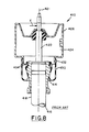
- Figure 8 represents a conventional air strut 410 which incorporates a conventional shock absorber 418 with a shock rod 420 extending axially outward from the outer body 416.
- a piston 414 Securely fastened concentrically around the outer body is a piston 414 which is mounted such that the axis of rotation of the piston is exactly coincident with the axis of rotation 421 of the shock absorber and rod.
- the flexible rubber member 430 is sealing attached to the piston 414 and at the opposite end to a volume can 426 by swage rings 432,434 to form the internal pneumatic working cavity 424.
- This inline symmetric airspring strut suspension member exhibits no side loading force capability which makes it unlike the suspension members of this invention.
- the concentric conventional airspring strut assembly of Figure 8 has a deadband of 5-6cm.
- the side load compensating airspring of Figure 6 yielded a deadband of only l-2cm.
- the kind of test results on dynamic and static type testing of stiction and side load compensating characteristics translate generally to a softer ride.
- the test results of Tables I and II show that the struts of this invention overcome the stiction problem of conventional inline air strut configurations.
- the airspring suspension member of this invention further provides the ability of the suspension to be tuned to particular desired ride characteristics.
- the strut may be inflated to higher pressures in the working cavity to compensate for higher vehicle loading and thereby maintaining a consistent vehicle height. A lower spring rate is obtainable and a variable spring rate is possible by utilizing varying pressures within the pneumatic working cavity of the airspring of the suspension member of the suspension strut.
- the flexible membrane which is cut in a plane oblique or non-perpendicular to the axis of the flexible membrane may be utilized with the offset piston of Figure 5 or 6 or the eccentric pistons of Figures 2 and 7.
Landscapes
- Engineering & Computer Science (AREA)
- Mechanical Engineering (AREA)
- General Engineering & Computer Science (AREA)
- Vehicle Body Suspensions (AREA)
- Fluid-Damping Devices (AREA)
Applications Claiming Priority (2)
| Application Number | Priority Date | Filing Date | Title |
|---|---|---|---|
| US06/802,144 US4688774A (en) | 1985-11-27 | 1985-11-27 | Side load compensating air suspension |
| US802144 | 1997-02-19 |
Publications (2)
| Publication Number | Publication Date |
|---|---|
| EP0225271A1 true EP0225271A1 (de) | 1987-06-10 |
| EP0225271B1 EP0225271B1 (de) | 1992-02-26 |
Family
ID=25182953
Family Applications (1)
| Application Number | Title | Priority Date | Filing Date |
|---|---|---|---|
| EP86630176A Expired - Lifetime EP0225271B1 (de) | 1985-11-27 | 1986-11-24 | Querkraftkompensierende Luftfeder |
Country Status (11)
| Country | Link |
|---|---|
| US (2) | US4688774A (de) |
| EP (1) | EP0225271B1 (de) |
| JP (1) | JPH069923B2 (de) |
| KR (1) | KR920007838B1 (de) |
| AU (1) | AU595844B2 (de) |
| BR (1) | BR8605730A (de) |
| CA (1) | CA1287069C (de) |
| DE (1) | DE3683992D1 (de) |
| ES (1) | ES2003530A6 (de) |
| IN (1) | IN172011B (de) |
| MX (1) | MX166180B (de) |
Cited By (9)
| Publication number | Priority date | Publication date | Assignee | Title |
|---|---|---|---|---|
| EP0259245A3 (en) * | 1986-09-02 | 1988-08-24 | The Goodyear Tire & Rubber Company | Airspring with partial restraining sleeve |
| US4817928A (en) * | 1987-10-09 | 1989-04-04 | Paton H N | Suspension system |
| EP0253261A3 (en) * | 1986-07-14 | 1989-07-26 | The Firestone Tire & Rubber Company | Air spring suspension system |
| EP0318696A3 (en) * | 1987-12-04 | 1989-07-26 | The Firestone Tire & Rubber Company | Air spring suspension system with dual path isolation |
| EP0395214A1 (de) * | 1989-04-24 | 1990-10-31 | General Motors Corporation | Endhalterung für Luftfeder in einer Federbeinaufhängung |
| GB2299146A (en) * | 1995-03-13 | 1996-09-25 | Daimler Benz Ag | Air-spring leg |
| WO1998026947A1 (de) * | 1996-12-17 | 1998-06-25 | Phoenix Aktiengesellschaft | Luftfedersystem |
| WO2012107283A1 (de) * | 2011-02-11 | 2012-08-16 | Continental Teves Ag & Co. Ohg | Kolben für eine luftfeder |
| EP2524828A1 (de) * | 2011-05-17 | 2012-11-21 | Carl Freudenberg KG | Lager sowie Lageranordnung |
Families Citing this family (52)
| Publication number | Priority date | Publication date | Assignee | Title |
|---|---|---|---|---|
| US5135203A (en) * | 1986-06-23 | 1992-08-04 | Monroe Auto Equipment Company | Vehicle leveling shock absorber assembly |
| US4989844A (en) * | 1986-06-23 | 1991-02-05 | Monroe Auto Equipment Company | Vehicle leveling shock absorber assembly |
| US4844429A (en) * | 1986-11-10 | 1989-07-04 | The Firestone Tire & Rubber Company | Die spring construction |
| FR2609128B1 (fr) * | 1986-12-30 | 1991-05-24 | Sirven Jacques | Amortisseur a compensation de charge |
| JP2662218B2 (ja) * | 1987-04-03 | 1997-10-08 | 株式会社ブリヂストン | 空気ばね |
| US4796870A (en) * | 1987-05-18 | 1989-01-10 | The Firestone Tire & Rubber Company | Suspension system for vehicles containing combination isolator mount and air spring closure |
| US4779893A (en) * | 1987-09-24 | 1988-10-25 | General Motors Corporation | Strut type vehicle wheel suspension |
| US4826204A (en) * | 1988-06-20 | 1989-05-02 | General Motors Corporation | Laterally offset dual volume air damper suspension strut with minimized side load |
| US4883288A (en) * | 1988-10-20 | 1989-11-28 | General Motors Corporation | Suspension strut with side load support |
| DE3836897A1 (de) * | 1988-10-29 | 1990-05-03 | Stabilus Gmbh | Ventilierbare schutzhuelle fuer die kolbenstange eines hydropneumatischen verstellelements |
| US4988082A (en) * | 1989-07-18 | 1991-01-29 | General Motors Corporation | Spliced air sleeve assembly for air spring damper |
| US5180144A (en) * | 1991-09-03 | 1993-01-19 | General Motors Corporation | Air spring module for a damper |
| US5348266A (en) * | 1992-03-27 | 1994-09-20 | Kinetic Systems, Inc. | Reduced horizontal stiffness vibration isolation system |
| US5549269A (en) * | 1992-03-27 | 1996-08-27 | Gertel; Maurice | Gas spring assembly |
| US5363743A (en) * | 1993-04-14 | 1994-11-15 | Eaton Corporation | Fluid pressure servomotor |
| DE69822677T2 (de) | 1997-01-06 | 2005-02-10 | The Gates Corp., Denver | Querkraftkompensierende Luftfeder für eine Fahrzeugaufhängung und Verfahren |
| US5752692A (en) | 1997-01-06 | 1998-05-19 | The Gates Corporation | Side load compensating airspring strut |
| US5934171A (en) * | 1997-07-24 | 1999-08-10 | Cymer, Inc. | Flexible mount for hydraulic/pneumatic cylinder and the like |
| WO2000077417A1 (en) | 1999-06-11 | 2000-12-21 | The Gates Corporation | Dual lobe airspring |
| JP4181277B2 (ja) * | 1999-06-29 | 2008-11-12 | 株式会社ブリヂストン | 空気ばね用ダイヤフラム |
| US6109598A (en) * | 1999-06-29 | 2000-08-29 | Bridgestone/Firestone, Inc. | Air spring bumper utilizing a combination of materials |
| US6607186B2 (en) * | 2000-05-01 | 2003-08-19 | Bret Voelkel | Shock absorber |
| US6561747B2 (en) * | 2000-07-11 | 2003-05-13 | Caterpillar S.A.R.L. | Ejector arrangement for a work machine |
| US7798295B2 (en) * | 2001-01-03 | 2010-09-21 | Jurrens Jesse A | Air-bag suspension system |
| DE10229584B4 (de) * | 2001-07-11 | 2008-07-31 | Vibracoustic Gmbh & Co. Kg | Federbein für eine Radaufhängung von Fahrzeugen mit einer Anordnung zur Kompensation von Querkräften |
| US6827342B2 (en) * | 2002-02-27 | 2004-12-07 | Zf Sachs Ag | Shock absorber |
| US7178794B2 (en) * | 2002-09-10 | 2007-02-20 | Seagate Technology Llc | Fluid isolator assembly and floating elastomeric damping element |
| US6902155B1 (en) | 2002-09-20 | 2005-06-07 | Freudenberg-Nok General Partnership | Air spring elliptical piston |
| US20040080086A1 (en) * | 2002-10-23 | 2004-04-29 | Mansueto Mark J. | Resilient bushing mount for a vehicle suspension |
| DE10302211B4 (de) * | 2003-01-22 | 2006-02-02 | Zf Sachs Ag | Schwingungsdämpfer |
| KR100527710B1 (ko) * | 2003-05-21 | 2005-11-09 | 현대자동차주식회사 | 리어스트럿어셈블리의 상단 마운팅부 구조 |
| US6899049B2 (en) * | 2003-10-29 | 2005-05-31 | Donald H. Gehring | Apparatus and method of constructing offshore platforms |
| US7380799B2 (en) * | 2003-11-05 | 2008-06-03 | Bfs Diversified Products, Llc | Adjustable vehicle suspension system with adjustable-rate air spring |
| DE102004010945A1 (de) * | 2004-03-03 | 2005-09-22 | Continental Aktiengesellschaft | Luftfeder für ein radführendes Federbein eines Kraftfahrzeuges |
| US7077052B2 (en) * | 2004-08-06 | 2006-07-18 | Arvinmeritor Technology, Llc | Strut assembly with inverted air spring configuration |
| DE102004058104B4 (de) * | 2004-12-01 | 2008-08-07 | Thyssenkrupp Bilstein Suspension Gmbh | Auflagerkörper zur Abstützung eines elastischen Abstützelements |
| FR2912793A1 (fr) * | 2007-02-19 | 2008-08-22 | Trelleborg Modyn Soc Par Actio | Support antivibratoire et dispositif amortisseur antivibratoire employant ledit support |
| US20100117319A1 (en) * | 2008-11-12 | 2010-05-13 | Lockheed Martin Corporation | Vehicle and Trailer Set With Interchangeable Suspension Assemblies |
| EP2412999A1 (de) * | 2010-07-28 | 2012-02-01 | Carl Freudenberg KG | Hydraulisch dämpfendes Lager |
| CA2751934A1 (en) * | 2010-09-10 | 2012-03-10 | Alcon Industries, Inc. | Furnace furniture |
| DE102012223112A1 (de) * | 2012-12-13 | 2014-06-18 | Continental Teves Ag & Co. Ohg | Verfahren zur Herstellung eines Luftfederkolbens und Luftfederkolben |
| JP6006109B2 (ja) * | 2012-12-25 | 2016-10-12 | 株式会社ショーワ | エアばね付ダンパ |
| DE102013110148A1 (de) * | 2013-09-16 | 2015-04-02 | Dr. Ing. H.C. F. Porsche Aktiengesellschaft | Luftfeder-Dämpfer-Vorrichtung für ein Kraftfahrzeug |
| US9290231B1 (en) * | 2015-05-19 | 2016-03-22 | Jesse Jurrens | Vehicle suspension element |
| DE102015007743B4 (de) * | 2015-06-17 | 2018-02-15 | Anvis Deutschland Gmbh | Schublager und druckluftbeaufschlagter Stoßdämpfer |
| DE102016210121B4 (de) | 2016-06-08 | 2022-02-03 | Ford Global Technologies, Llc | Luftfeder für Fahrwerke von Fahrzeugen |
| US10245915B2 (en) | 2017-03-30 | 2019-04-02 | Cnh Industrial America Llc | Task-specific ride-height and speed control of an agricultural product applicator with air strut suspension |
| US10865734B2 (en) | 2017-12-06 | 2020-12-15 | Ai Alpine Us Bidco Inc | Piston assembly with offset tight land profile |
| US11859688B2 (en) * | 2019-12-31 | 2024-01-02 | Firestone Industrial Products Company, Llc | Gas spring and damper assemblies as well as suspension systems including same |
| US11548345B1 (en) * | 2020-09-02 | 2023-01-10 | Afco Performance Group, Llc | Suspension component for utility vehicles |
| CN115306853A (zh) * | 2022-08-04 | 2022-11-08 | 广东溢康通空气弹簧有限公司 | 膜式空气弹簧以及复合减震器 |
| KR20240030164A (ko) * | 2022-08-30 | 2024-03-07 | 주식회사 일진 | 차량용 에어 스프링 어셈블리 |
Citations (9)
| Publication number | Priority date | Publication date | Assignee | Title |
|---|---|---|---|---|
| US2980441A (en) * | 1958-11-28 | 1961-04-18 | Gen Motors Corp | Fluid suspension unit |
| FR1391349A (fr) * | 1964-04-20 | 1965-03-05 | Gomma Antivibranti Applic | Suspension élastique pour véhicules |
| US3351337A (en) * | 1962-07-20 | 1967-11-07 | Summimoto Metal Ind Ltd | Air spring |
| US3363893A (en) * | 1965-02-04 | 1968-01-16 | Girling Ltd | Vehicle suspension device |
| DE1780370A1 (de) * | 1968-01-17 | 1971-12-30 | Studi Impianti Consulenze Automotoristische Sica-S.R.L., Mailand (Italien) | Einzelradaufhängung |
| DE2063448A1 (de) * | 1970-12-23 | 1972-07-06 | Fichtel & Sachs Ag, 8720 Schweinfurt | Aus Stoßdämpfer und Luftfeder bestehendes Federbein |
| FR2319813A1 (fr) * | 1975-08-01 | 1977-02-25 | Renault | Element elastique de fixation d'amortisseur porteur |
| US4332397A (en) | 1980-07-07 | 1982-06-01 | General Motors Corporation | Steerable suspension strut with pneumatic spring |
| US4386791A (en) | 1981-07-06 | 1983-06-07 | Ford Motor Company | Actively controlled suspension system and height sensor |
Family Cites Families (13)
| Publication number | Priority date | Publication date | Assignee | Title |
|---|---|---|---|---|
| GB792310A (en) * | 1955-02-07 | 1958-03-26 | Ford Motor Co | Improvements in or relating to wheel suspensions for motor vehicles |
| GB828606A (en) * | 1956-01-05 | 1960-02-17 | Moulton Development Ltd | Improvements in fluid pressure systems and apparatus |
| NL220888A (de) * | 1956-10-02 | |||
| US2893104A (en) * | 1957-05-23 | 1959-07-07 | Gen Motors Corp | Air suspension |
| GB1034471A (en) * | 1962-01-13 | 1966-06-29 | Sumitomo Metal Ind | Air spring |
| NL137412C (de) * | 1964-09-24 | |||
| CA1050060A (en) * | 1974-08-30 | 1979-03-06 | Johan H. Keijzer | Vehicle suspension strut |
| US3954257A (en) * | 1974-08-30 | 1976-05-04 | Monroe Belgium N. V. | Suspension strut |
| DE2750667C2 (de) * | 1977-11-12 | 1980-01-24 | Daimler-Benz Ag, 7000 Stuttgart | Luftfeder für Kraftfahrzeuge |
| US4274655A (en) * | 1979-10-29 | 1981-06-23 | General Motors Corporation | Resilient mount for MacPherson strut |
| JPS6036965B2 (ja) * | 1981-07-30 | 1985-08-23 | 日産自動車株式会社 | 操向車輪の懸架装置 |
| US4445673A (en) * | 1982-01-15 | 1984-05-01 | Applied Power Inc. | Shock absorber and air spring assembly |
| EP0210553B1 (de) * | 1985-07-26 | 1989-08-30 | Audi Ag | Vorrichtung zum Ausgleich der Radaufstands-Querkräfte an einem Federbein |
-
1985
- 1985-11-27 US US06/802,144 patent/US4688774A/en not_active Expired - Lifetime
-
1986
- 1986-07-17 IN IN642/DEL/86A patent/IN172011B/en unknown
- 1986-11-14 KR KR1019860009616A patent/KR920007838B1/ko not_active Expired
- 1986-11-20 BR BR8605730A patent/BR8605730A/pt not_active IP Right Cessation
- 1986-11-21 MX MX004399A patent/MX166180B/es unknown
- 1986-11-21 ES ES8603118A patent/ES2003530A6/es not_active Expired
- 1986-11-24 EP EP86630176A patent/EP0225271B1/de not_active Expired - Lifetime
- 1986-11-24 DE DE8686630176T patent/DE3683992D1/de not_active Expired - Fee Related
- 1986-11-25 JP JP61278928A patent/JPH069923B2/ja not_active Expired - Fee Related
- 1986-11-26 AU AU65716/86A patent/AU595844B2/en not_active Ceased
- 1986-11-26 CA CA000523878A patent/CA1287069C/en not_active Expired - Fee Related
-
1989
- 1989-03-02 US US07/308,340 patent/US4911416A/en not_active Expired - Fee Related
Patent Citations (9)
| Publication number | Priority date | Publication date | Assignee | Title |
|---|---|---|---|---|
| US2980441A (en) * | 1958-11-28 | 1961-04-18 | Gen Motors Corp | Fluid suspension unit |
| US3351337A (en) * | 1962-07-20 | 1967-11-07 | Summimoto Metal Ind Ltd | Air spring |
| FR1391349A (fr) * | 1964-04-20 | 1965-03-05 | Gomma Antivibranti Applic | Suspension élastique pour véhicules |
| US3363893A (en) * | 1965-02-04 | 1968-01-16 | Girling Ltd | Vehicle suspension device |
| DE1780370A1 (de) * | 1968-01-17 | 1971-12-30 | Studi Impianti Consulenze Automotoristische Sica-S.R.L., Mailand (Italien) | Einzelradaufhängung |
| DE2063448A1 (de) * | 1970-12-23 | 1972-07-06 | Fichtel & Sachs Ag, 8720 Schweinfurt | Aus Stoßdämpfer und Luftfeder bestehendes Federbein |
| FR2319813A1 (fr) * | 1975-08-01 | 1977-02-25 | Renault | Element elastique de fixation d'amortisseur porteur |
| US4332397A (en) | 1980-07-07 | 1982-06-01 | General Motors Corporation | Steerable suspension strut with pneumatic spring |
| US4386791A (en) | 1981-07-06 | 1983-06-07 | Ford Motor Company | Actively controlled suspension system and height sensor |
Non-Patent Citations (1)
| Title |
|---|
| PATENTS ABSTRACTS OF JAPAN, vol. 6, no. 204 (M-164)[1082], 15th October 1982; & JP-A-57 110 517 (FUJI JUKOGYO K.K.) 09-07-1982 * |
Cited By (14)
| Publication number | Priority date | Publication date | Assignee | Title |
|---|---|---|---|---|
| EP0253261A3 (en) * | 1986-07-14 | 1989-07-26 | The Firestone Tire & Rubber Company | Air spring suspension system |
| EP0259245A3 (en) * | 1986-09-02 | 1988-08-24 | The Goodyear Tire & Rubber Company | Airspring with partial restraining sleeve |
| US5129634A (en) * | 1986-09-02 | 1992-07-14 | The Goodyear Tire & Rubber Company | Airspring with partial restraining sleeve |
| US4817928A (en) * | 1987-10-09 | 1989-04-04 | Paton H N | Suspension system |
| EP0318696A3 (en) * | 1987-12-04 | 1989-07-26 | The Firestone Tire & Rubber Company | Air spring suspension system with dual path isolation |
| EP0395214A1 (de) * | 1989-04-24 | 1990-10-31 | General Motors Corporation | Endhalterung für Luftfeder in einer Federbeinaufhängung |
| GB2299146A (en) * | 1995-03-13 | 1996-09-25 | Daimler Benz Ag | Air-spring leg |
| GB2299146B (en) * | 1995-03-13 | 1997-09-10 | Daimler Benz Ag | Air-spring leg |
| US5667203A (en) * | 1995-03-13 | 1997-09-16 | Mercedes-Benz Ag | Air-spring leg |
| WO1998026947A1 (de) * | 1996-12-17 | 1998-06-25 | Phoenix Aktiengesellschaft | Luftfedersystem |
| US6227527B1 (en) | 1996-12-17 | 2001-05-08 | Phoenix Aktiengesellschaft | Pneumatic suspension system |
| WO2012107283A1 (de) * | 2011-02-11 | 2012-08-16 | Continental Teves Ag & Co. Ohg | Kolben für eine luftfeder |
| EP2524828A1 (de) * | 2011-05-17 | 2012-11-21 | Carl Freudenberg KG | Lager sowie Lageranordnung |
| WO2012156055A1 (de) * | 2011-05-17 | 2012-11-22 | Carl Freudenberg Kg | Lager sowie lageranordnung |
Also Published As
| Publication number | Publication date |
|---|---|
| US4911416A (en) | 1990-03-27 |
| JPH069923B2 (ja) | 1994-02-09 |
| IN172011B (de) | 1993-03-13 |
| ES2003530A6 (es) | 1988-11-01 |
| JPS62131810A (ja) | 1987-06-15 |
| EP0225271B1 (de) | 1992-02-26 |
| AU6571686A (en) | 1987-06-04 |
| MX166180B (es) | 1992-12-23 |
| AU595844B2 (en) | 1990-04-12 |
| KR920007838B1 (ko) | 1992-09-18 |
| BR8605730A (pt) | 1987-08-18 |
| CA1287069C (en) | 1991-07-30 |
| KR870004847A (ko) | 1987-06-02 |
| US4688774A (en) | 1987-08-25 |
| DE3683992D1 (de) | 1992-04-02 |
Similar Documents
| Publication | Publication Date | Title |
|---|---|---|
| US4911416A (en) | Side load compensating air suspension | |
| CA1320222C (en) | Airspring with partial restraining sleeve | |
| KR950003213B1 (ko) | 공기 스프링 현가 장치 | |
| US4762308A (en) | Damping valve for air spring suspension systems | |
| EP0318696B1 (de) | Luftfederaufhängung mit zweiseitiger Isolierung | |
| US5308104A (en) | Steer-sensitive jounce bumper and bump plate | |
| US4697797A (en) | Combination pneumatic spring and shock absorbing apparatus | |
| US6220409B1 (en) | Stroke dependent bypass | |
| EP0000287B1 (de) | Hydropneumatisches Federbein für Fahrzeuge | |
| US5449150A (en) | Vibration damping device with an electrode and having rolling lobes of different radii | |
| US4518154A (en) | Pneumatic spring, especially for motor vehicles | |
| US4742996A (en) | Pneumatic strut | |
| JP3268454B2 (ja) | 車輪の懸架方法及び懸架装置 | |
| US4961594A (en) | End retainer for air spring in strut suspension | |
| US4988082A (en) | Spliced air sleeve assembly for air spring damper | |
| US5392882A (en) | Dynamic absorber suspension strut | |
| JPS597057B2 (ja) | 車輛用油圧緩衝装置 | |
| JPS5885704A (ja) | 車輛用懸架装置 | |
| JPS5841398Y2 (ja) | カ−トリツジシヨツクアブソ−バ | |
| US3154301A (en) | Suspension device | |
| US20230067276A1 (en) | Shock absorber | |
| KR920008031Y1 (ko) | 자동차용 2중 쇽 업소오버 | |
| JPS5913138Y2 (ja) | 車輛用油圧緩衝装置 | |
| JPH048657B2 (de) | ||
| JPH0581551U (ja) | ショックアブソーバの構造 |
Legal Events
| Date | Code | Title | Description |
|---|---|---|---|
| PUAI | Public reference made under article 153(3) epc to a published international application that has entered the european phase |
Free format text: ORIGINAL CODE: 0009012 |
|
| 17P | Request for examination filed |
Effective date: 19861204 |
|
| AK | Designated contracting states |
Kind code of ref document: A1 Designated state(s): DE FR GB IT SE |
|
| 17Q | First examination report despatched |
Effective date: 19890425 |
|
| ITTA | It: last paid annual fee | ||
| GRAA | (expected) grant |
Free format text: ORIGINAL CODE: 0009210 |
|
| AK | Designated contracting states |
Kind code of ref document: B1 Designated state(s): DE FR GB IT SE |
|
| REF | Corresponds to: |
Ref document number: 3683992 Country of ref document: DE Date of ref document: 19920402 |
|
| ET | Fr: translation filed | ||
| ITF | It: translation for a ep patent filed | ||
| PLBE | No opposition filed within time limit |
Free format text: ORIGINAL CODE: 0009261 |
|
| STAA | Information on the status of an ep patent application or granted ep patent |
Free format text: STATUS: NO OPPOSITION FILED WITHIN TIME LIMIT |
|
| 26N | No opposition filed | ||
| EAL | Se: european patent in force in sweden |
Ref document number: 86630176.5 |
|
| PGFP | Annual fee paid to national office [announced via postgrant information from national office to epo] |
Ref country code: SE Payment date: 19961018 Year of fee payment: 11 |
|
| PG25 | Lapsed in a contracting state [announced via postgrant information from national office to epo] |
Ref country code: SE Free format text: LAPSE BECAUSE OF NON-PAYMENT OF DUE FEES Effective date: 19971125 |
|
| EUG | Se: european patent has lapsed |
Ref document number: 86630176.5 |
|
| REG | Reference to a national code |
Ref country code: GB Ref legal event code: IF02 |
|
| PGFP | Annual fee paid to national office [announced via postgrant information from national office to epo] |
Ref country code: GB Payment date: 20021002 Year of fee payment: 17 |
|
| PGFP | Annual fee paid to national office [announced via postgrant information from national office to epo] |
Ref country code: FR Payment date: 20021105 Year of fee payment: 17 |
|
| PGFP | Annual fee paid to national office [announced via postgrant information from national office to epo] |
Ref country code: DE Payment date: 20021127 Year of fee payment: 17 |
|
| PG25 | Lapsed in a contracting state [announced via postgrant information from national office to epo] |
Ref country code: GB Free format text: LAPSE BECAUSE OF NON-PAYMENT OF DUE FEES Effective date: 20031124 |
|
| PG25 | Lapsed in a contracting state [announced via postgrant information from national office to epo] |
Ref country code: DE Free format text: LAPSE BECAUSE OF NON-PAYMENT OF DUE FEES Effective date: 20040602 |
|
| GBPC | Gb: european patent ceased through non-payment of renewal fee |
Effective date: 20031124 |
|
| PG25 | Lapsed in a contracting state [announced via postgrant information from national office to epo] |
Ref country code: FR Free format text: LAPSE BECAUSE OF NON-PAYMENT OF DUE FEES Effective date: 20040730 |
|
| REG | Reference to a national code |
Ref country code: FR Ref legal event code: ST |
|
| PG25 | Lapsed in a contracting state [announced via postgrant information from national office to epo] |
Ref country code: IT Free format text: LAPSE BECAUSE OF NON-PAYMENT OF DUE FEES;WARNING: LAPSES OF ITALIAN PATENTS WITH EFFECTIVE DATE BEFORE 2007 MAY HAVE OCCURRED AT ANY TIME BEFORE 2007. THE CORRECT EFFECTIVE DATE MAY BE DIFFERENT FROM THE ONE RECORDED. Effective date: 20051124 |