EP0225419B1 - Gebäude - Google Patents
Gebäude Download PDFInfo
- Publication number
- EP0225419B1 EP0225419B1 EP85850393A EP85850393A EP0225419B1 EP 0225419 B1 EP0225419 B1 EP 0225419B1 EP 85850393 A EP85850393 A EP 85850393A EP 85850393 A EP85850393 A EP 85850393A EP 0225419 B1 EP0225419 B1 EP 0225419B1
- Authority
- EP
- European Patent Office
- Prior art keywords
- building
- floor
- building according
- ramps
- elements
- Prior art date
- Legal status (The legal status is an assumption and is not a legal conclusion. Google has not performed a legal analysis and makes no representation as to the accuracy of the status listed.)
- Expired
Links
- XLYOFNOQVPJJNP-UHFFFAOYSA-N water Substances O XLYOFNOQVPJJNP-UHFFFAOYSA-N 0.000 claims abstract description 8
- 239000002699 waste material Substances 0.000 claims abstract description 4
- 238000010276 construction Methods 0.000 claims description 6
- 238000012986 modification Methods 0.000 description 6
- 230000004048 modification Effects 0.000 description 6
- 230000008901 benefit Effects 0.000 description 5
- 230000004308 accommodation Effects 0.000 description 3
- 238000013461 design Methods 0.000 description 3
- 238000011161 development Methods 0.000 description 3
- 230000005611 electricity Effects 0.000 description 3
- 230000008859 change Effects 0.000 description 2
- 238000007689 inspection Methods 0.000 description 2
- 230000007774 longterm Effects 0.000 description 2
- 230000004075 alteration Effects 0.000 description 1
- 238000013459 approach Methods 0.000 description 1
- 230000015556 catabolic process Effects 0.000 description 1
- 239000010791 domestic waste Substances 0.000 description 1
- 239000011521 glass Substances 0.000 description 1
- 210000002837 heart atrium Anatomy 0.000 description 1
- 238000010438 heat treatment Methods 0.000 description 1
- 238000009434 installation Methods 0.000 description 1
- 238000012423 maintenance Methods 0.000 description 1
- 238000007726 management method Methods 0.000 description 1
- 238000004519 manufacturing process Methods 0.000 description 1
- 238000005259 measurement Methods 0.000 description 1
- 238000000034 method Methods 0.000 description 1
- 238000011084 recovery Methods 0.000 description 1
- 238000007789 sealing Methods 0.000 description 1
- 238000009423 ventilation Methods 0.000 description 1
Images
Classifications
-
- E—FIXED CONSTRUCTIONS
- E04—BUILDING
- E04H—BUILDINGS OR LIKE STRUCTURES FOR PARTICULAR PURPOSES; SWIMMING OR SPLASH BATHS OR POOLS; MASTS; FENCING; TENTS OR CANOPIES, IN GENERAL
- E04H1/00—Buildings or groups of buildings for dwelling or office purposes; General layout, e.g. modular co-ordination or staggered storeys
- E04H1/02—Dwelling houses; Buildings for temporary habitation, e.g. summer houses
- E04H1/04—Apartment houses arranged in two or more levels
-
- E—FIXED CONSTRUCTIONS
- E04—BUILDING
- E04H—BUILDINGS OR LIKE STRUCTURES FOR PARTICULAR PURPOSES; SWIMMING OR SPLASH BATHS OR POOLS; MASTS; FENCING; TENTS OR CANOPIES, IN GENERAL
- E04H1/00—Buildings or groups of buildings for dwelling or office purposes; General layout, e.g. modular co-ordination or staggered storeys
- E04H1/005—Modulation co-ordination
Definitions
- a characteristic feature of fostering communities such as towns, cities, and like compactly settled areas resides in their constant growth and development.
- the development of communities is not solely restricted to the creation of new suburbs, but also involves the rebuilding and, at times, the demolishment of existing buildings, which, due to changing circumstances, no longer suit the purpose for which they were originally built.
- the present invention is based on the concept of planning new buildings in a manner which will enable them to be modified and altered to suit changing requirements when the time for alteration arises, thereby eliminating the need to demolish existing buildings and to rebuild to specification, and avoiding the heavy costs involved therewith. Since the aims and purposes of a fostering community change with time, it is feasible to suppose that the individual units and buildings, in the area can also be modified to accommodate the needs prevailing at that point in time.
- a modern apartment block for example, is expected to last from 50-60 years. Consequently, a block of apartments erected today is expected to house families, many of which are still to be born, until the middle of the next century.
- present day apartments are "type” designed, i.e. built to accommodate given family sizes, e.g. "families of four", “a single person”, etc., since more profit is obtained when the number of "type-design" apartments is rationalized and kept low.
- an object of the invention is to provide an arrangement in building structures which will eliminate a major part of the aforesaid difficulties without requiring comprehensive modifications of outdated buildings or the replacement of such buildings when wishing to meet changing circumstances. Accordingly, the present invention relates to a novel type of building which can be readily modified at low cost to satisfy changing functions, and which is also designed to meet the needs and requirements of handicapped people.
- the invention has as its starting point a known building comprising floor structures which are carried on load-bearing supports, such as pillars, wall sections or the like and which extend freely between said supports, and further comprising exterior and/or internal wall elements mounted between the floor structures, of which wall elements at least some can be placed and/or re-positioned in order to provide flexibility with respect to the various rooms or enclosed areas in the building, and arranged in the proximity of respective floor structures are horizontal walk surfaces of which at least some serve as entry corridors to the various areas of a respective floor plan.
- load-bearing supports such as pillars, wall sections or the like and which extend freely between said supports
- exterior and/or internal wall elements mounted between the floor structures, of which wall elements at least some can be placed and/or re-positioned in order to provide flexibility with respect to the various rooms or enclosed areas in the building, and arranged in the proximity of respective floor structures are horizontal walk surfaces of which at least some serve as entry corridors to the various areas of a respective floor plan.
- the invention is mainly characterized in that said horizontal walk surfaces join with a system of ramps extending between the different floor structure levels, and in that service lines, such as electric cables, water pipes, waste pipes and the like, extending into and out of said rooms and enclosed areas, are placed in or adjacent exterior walls in a manner to be accessible from without and from the horizontal walk surfaces.
- service lines such as electric cables, water pipes, waste pipes and the like, extending into and out of said rooms and enclosed areas, are placed in or adjacent exterior walls in a manner to be accessible from without and from the horizontal walk surfaces.
- the horizontal walk surfaces can be arranged centrally in the transverse direction of the building and at a suitable distance apart in the longitudinal direction thereof.
- the ramps connecting the various floor levels can lead directly to corresponding positions in the transverse and vertical directions of the building.
- the present invention provides a novel building which may be given any desired number of floors and which comprises a basic building structure which can be completed with the use of suitable standardized concrete building elements.
- a building of this type can be used over a long period of time without requiring comprehensive restructuring work, and can be readily modified to suit various different purposes.
- one and the same building can be readily altered for such widely different usages as varying types of living accommodation (families, sheltered homes for the aged, youth accommodation, with or without service functions), office facilities, schools, childrens play-schools, medicare centres and like localities.
- Each floor level of the building affords maximum flexibility with regard to the division and allocation of the space available and with regard to the general planning of the floors, such as to satisfy widely varying needs and quality demands. It is also possible to simply "dismantle" a building constructed in accordance with the invention and re-construct it on another site in a different guise or form.
- a building constructed in accordance with the invention also affords good possibilities of achieving optimal running economy, since the inherent elasticity of the building with regard to room size and space in general, together with its flexibility with regard to the manner in which the various levels or floors are planned, enables electricity, heat, water, etc. to be drawn to individual apartments and rooms and paid for separately by respective tenants, and also greatly facilitates the disposal of domestic waste, all of which is meaningful and of real worth to the tenants involved.
- a building constructed in accordance with the present invention also enables the instigation of a novel conception of management and administration in which a tenant may be given the right, preferably contractually, to modify or alter the living space rented by the tenant, or any other form of rented space.
- the service lines are accessible from outside the building. This greatly facilitates all inspection work and maintenance work required to be carried out, and also enables the service lines to be readily shifted and re-drawn in conjunction with modifications to the various rooms in the building.
- the respective floor structures are preferably dimensioned to support purpose-built rooms of prescribed load-bearing capacity.
- the structural floor height should also be dimensioned for purpose-built rooms of prescribed ceiling heights, for the same reasons.
- a particularly versatile building coupled with optimal disposition ability of the various floor levels can be achieved when the span of the free-span floor structures corresponds to the depth of the building.
- a building constructed in accordance with the invention may comprise mutually different types of mod- ulized building elements or units. This enables such a building to be erected more readily and more cheaply than would otherwise be the case, despite all the advantages afforded by such a building.
- the free-span floor structures may include concrete elements which have been cast in vertical moulds thereby avoiding plastic deformation to a large extent.
- the ramps and/or the horizontal walk surfaces may be made common to a plurality of building structures. This does not only make construction less expensive but also provides the architect with the valuable possibility of varying the appearance of such groups of buildings.
- the ramps and/or the horizontal walk surfaces may either be enclosed or open, depending largely on prevailing climatic conditions.
- ramps extend within a space which is separate from an associated building or buildings, for example an extended conservatory designed as a winter garden or the like in which the ramps either extend along the walls thereof, while leaving a central free- space in the building, or are arranged centrally of the building so as to leave the spaces around the walls free.
- a ramp-enclosure of this kind affords scope for the inclusion of tasteful and practical arrangements, plants etc., interdispersed with childrens play areas and lounge areas, surrounded by flowers, plants etc.
- Ramps and adjoining horizontal walk surfaces can also be arranged in a space which is not common solely to one building but which also connects with several adjacent buildings, for example in the form of a covered atrium between four adjacent building structures.
- At least one of the ramps of a building constructed in accordance with the invention can incorporate a so-called moving side-walk.
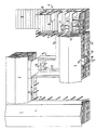
- the illustrated building complex comprises four elongated basic building structures or blocks 1-4 in the form of a balcony-access apartment block comprising two stories or floors, these building structures being arranged in pairs to present an "L"-configuration, and being mutually connected partly by horizontal walk surfaces or access balconies 5, common to all building structures, and partly by a further, centrally located building structure 6, which constitutes an area common to the remaining building structures 1-4.
- the illustrated central building structure 6 can fulfil a number of purposes, it is assumed that the central building structure of the illustrated embodiment primarily serves as the main entrance to the building complex and affords the requisite internal vertical connection between the various floor levels of said complex and the horizontal walk surfaces between the various apartments, offices or the like located on one and the same floor level but in different pairs of buildings 1,2 and 3,4 of said building complex.
- the illustrated building complex can be readily adapted at low costs to changing functional demands, and is so designed that handicapped people, and especially disabled people, are able to live and move in ease and comfort.
- the different building structures are each constructed from known load-bearing pillars 7 and wall-sections 8 which support free-span floor structures 9 therebetween.
- Known exterior and/or interior wall elements 10,11 are mounted between respective adjacent floor structures 9.
- the wall elements 8,10,11 of the building complex can be readily replaced and/or repositioned, to provide the requisite flexibility of the various rooms and like areas.
- the horizontal walk surfaces forming the access balconies 5 are arranged in connection with firstly the floor structures 9 forming the respective floors of the building, and secondly with a system of ramps 12 extending between the vaious floor-structure levels and located within the central, common-use building structure 6, these ramps together with the access balconies 5 being common to all building structures 1-4, 6 forming part of the building complex.
- the ramps 12 extend in a separate space or area provided within the central building 6 and are thus fully enclosed, whereas the horizontal walk surfaces or balconies 5 are solely covered by a roof structure. It will be understood, however, that both ramps and access balconies may be either fully open or fully enclosed, according to choice, and may also conceivably be placed in a common atrium-like area in the centre of a building, or at least the ramps may be placed in a space separate from the actual building itself, although this space must, of course, be connected with the horizontal walk surfaces or balconies served by the ramps.
- the ramp system 12 incorporated in the central building 6 of the illustrated building complex is assumed to be fitted with large glass wall-sections, so that the area providing access to the ramp system may be planned as a winter garden, with the possibility of providing play areas and recreation areas for the tenants.
- some or all of the balconies 5 may be extended so as to also include recreation areas or common areas of some kind or another.
- the basement is also preferably connected to the ramp system 12, in order to fulfil the object of the invention.
- the requirement placed on the foundations of a building constructed in accordance with the invention are no more than those required of conventional buildings.
- the floor structures 9 thereof should be dimensioned in a manner which enables them to support purpose-built rooms having prescribed load-bearing capacities.
- the structural room height should be dimensioned to provide purpose-built rooms having prescribed ceiling heights.
- the free-span floor structures 9 have a span which corresponds to the depth of the building, which as beforementioned provides for rational construction coupled with optimal possibilities with respect to the disposition of the various floors. From the aspect of rationalization, it is also expedient to use module-type building elements, and then, inter alia, floor-structure elements in the form of concrete units cast in vertical moulds and provided with an ultimately upwardly facing surface which satisfies prevailing floor standards from the time of manufacture.
- sealing means are conveniently placed between the edge-surfaces of respective wall elements and those building surfaces against which said edge-surfaces are intended to lie.
- the exchangeable and/or movable elements in the floor structures and walls of the building are also preferably provided with built-in permanent adjustment devices (not shown) effective to permit positional adjustment of said elements in order to obtain perfectly flush joins.
- All or some of the exterior walls of the building may, to advantage have load-bearing wall elements having a structural room height and length which are adapted to suit a particular purpose. Prior to being erected in the building, these wall elements are conveniently thermally insulated on the outwardly facing surfaces and provided with simple attachment means which enable suitable facing elements to be readily attached thereto and removed therefrom, thereby enabling the facade of the building to be changed at relatively low costs. Certain load-bearing exterior-wall elements are also suitably provided with duct ing through which the aforesaid service lines can be drawn.
- Each flat, office or like accommodation space in a building constructed in accordance with the invention may be supplied individually with electricity, cold water and a waste-disposal service.
- the collective part of these services is suitably placed so as to be accessible from outside the building. This enables each flat or other locality to prepare its own hot water, to be responsible for its own heating and ventilation, including the evacuation of stale air, the intake of fresh air and the recovery of heat. This renders the individual supply of electricity and water and the payment for such services more meaningful to the tenants concerned.
- a building constructed in accordance with the invention may also be provided with individual balconies 13, bay windows 14, conservatories 15, and garden dividers 16, capable of being erected, taken-down or dismantled or moved, thereby affording further possibilities of adapting the building during the various phases of its use.
- all interior walls and all fittings can be replaced without requiring work to be carried out on the basic structure of the building.
- the size of the apartments can be varied and the apartments re- planned, by converting room-dividing walls into apartment dividing walls.
- the building complex constitutes a block of apartments. It will be understood, how ever, that the building may also constitute a block of offices, an industrial hotel, a school, a play-centre or creche, or like localities, all within the scope of the invention. Thus, the invention is not restricted to the described and illustrated embodiment, and modifications can be made within the scope of the following claims.
Landscapes
- Engineering & Computer Science (AREA)
- Architecture (AREA)
- Civil Engineering (AREA)
- Structural Engineering (AREA)
- Buildings Adapted To Withstand Abnormal External Influences (AREA)
- Residential Or Office Buildings (AREA)
- Building Environments (AREA)
- Floor Finish (AREA)
Claims (15)
Priority Applications (4)
| Application Number | Priority Date | Filing Date | Title |
|---|---|---|---|
| EP85850393A EP0225419B1 (de) | 1985-12-09 | 1985-12-09 | Gebäude |
| AT85850393T ATE57735T1 (de) | 1985-12-09 | 1985-12-09 | Gebaeude. |
| DE198585850393T DE225419T1 (de) | 1985-12-09 | 1985-12-09 | Gebaeude. |
| DE8585850393T DE3580281D1 (de) | 1985-12-09 | 1985-12-09 | Gebaeude. |
Applications Claiming Priority (1)
| Application Number | Priority Date | Filing Date | Title |
|---|---|---|---|
| EP85850393A EP0225419B1 (de) | 1985-12-09 | 1985-12-09 | Gebäude |
Publications (2)
| Publication Number | Publication Date |
|---|---|
| EP0225419A1 EP0225419A1 (de) | 1987-06-16 |
| EP0225419B1 true EP0225419B1 (de) | 1990-10-24 |
Family
ID=8194728
Family Applications (1)
| Application Number | Title | Priority Date | Filing Date |
|---|---|---|---|
| EP85850393A Expired EP0225419B1 (de) | 1985-12-09 | 1985-12-09 | Gebäude |
Country Status (3)
| Country | Link |
|---|---|
| EP (1) | EP0225419B1 (de) |
| AT (1) | ATE57735T1 (de) |
| DE (2) | DE225419T1 (de) |
Families Citing this family (2)
| Publication number | Priority date | Publication date | Assignee | Title |
|---|---|---|---|---|
| RU2145657C1 (ru) * | 1999-05-24 | 2000-02-20 | Гинзбург Виталий Вениаминович | Многофункциональная кабельная система здания, способ формирования этой системы для строящегося или реставрируемого здания и способ повышения эксплуатационных долговечности и надежности этой системы |
| ATE299209T1 (de) | 2000-07-14 | 2005-07-15 | Europ D Etudes Et De Construct | Wandelement |
Family Cites Families (1)
| Publication number | Priority date | Publication date | Assignee | Title |
|---|---|---|---|---|
| DD82819A (de) * |
-
1985
- 1985-12-09 DE DE198585850393T patent/DE225419T1/de active Pending
- 1985-12-09 EP EP85850393A patent/EP0225419B1/de not_active Expired
- 1985-12-09 DE DE8585850393T patent/DE3580281D1/de not_active Expired - Fee Related
- 1985-12-09 AT AT85850393T patent/ATE57735T1/de not_active IP Right Cessation
Also Published As
| Publication number | Publication date |
|---|---|
| DE225419T1 (de) | 1987-10-15 |
| DE3580281D1 (de) | 1990-11-29 |
| ATE57735T1 (de) | 1990-11-15 |
| EP0225419A1 (de) | 1987-06-16 |
Similar Documents
| Publication | Publication Date | Title |
|---|---|---|
| US3643390A (en) | Modular building structure | |
| EP1273741B1 (de) | Mehrfamilienhaus | |
| US7765745B2 (en) | Reusable worker housing and methods relating thereto | |
| US3712007A (en) | Building system and components therefor | |
| US4098039A (en) | Multi-level building with prefabricated triangular cantilever units | |
| WO2017027752A1 (en) | Multi-story multi-unit buildings | |
| EP2181225B1 (de) | Mehrere module umfassendes gebäude | |
| US4035973A (en) | Bisectional architectural structure | |
| EP0225419A1 (de) | Gebäude | |
| EP1636446A1 (de) | Gebrauchsfertiges containerartiges haus | |
| US6079171A (en) | Disabled or handicapped accessible non-elevator building and method for making | |
| US3710521A (en) | Multistory buildings and walls thereof | |
| RU2121032C1 (ru) | Способ изготовления многоэтажного жилого дома и многоэтажный жилой дом | |
| WO2020149671A1 (ko) | 독립형 공동주택 시공 방법 | |
| Martynov | “LIRA CAD” LLC | |
| Mikryukova et al. | To the Question of the Development of Construction of High-Rise Buildings | |
| Clark | Workplace: Smart design studio | |
| US20050086874A1 (en) | Flexible, adaptable loft city | |
| Bray et al. | A building for technological and academic research | |
| RU26807U1 (ru) | Малоэтажный жилой дом конструкции "сапожниковой-макарова" | |
| Al-Azzawi | Energy-conscious design of low-cost housing—passive solar design of a new-built block of flats in London | |
| Seeley | Cost Implications of Design Variables and Quality Assurance | |
| AU2010297303A1 (en) | Apartment building having a plurality of stories | |
| Gupta | Standing Conference of Public Enterprise" New Delhi" | |
| Montaner | Selected Spanish Projects |
Legal Events
| Date | Code | Title | Description |
|---|---|---|---|
| PUAI | Public reference made under article 153(3) epc to a published international application that has entered the european phase |
Free format text: ORIGINAL CODE: 0009012 |
|
| AK | Designated contracting states |
Kind code of ref document: A1 Designated state(s): AT BE CH DE FR GB IT LI LU NL SE |
|
| ITCL | It: translation for ep claims filed |
Representative=s name: CALVANI SALVI VERONELLI |
|
| TCNL | Nl: translation of patent claims filed | ||
| EL | Fr: translation of claims filed | ||
| TCAT | At: translation of patent claims filed | ||
| DET | De: translation of patent claims | ||
| 17P | Request for examination filed |
Effective date: 19871020 |
|
| 17Q | First examination report despatched |
Effective date: 19881209 |
|
| RAP3 | Party data changed (applicant data changed or rights of an application transferred) |
Owner name: SKARNE SYSTEMUTVECKLING AB |
|
| RAP3 | Party data changed (applicant data changed or rights of an application transferred) |
Owner name: SKARNE SYSTEM AB |
|
| GRAA | (expected) grant |
Free format text: ORIGINAL CODE: 0009210 |
|
| ITF | It: translation for a ep patent filed | ||
| AK | Designated contracting states |
Kind code of ref document: B1 Designated state(s): AT BE CH DE FR GB IT LI LU NL SE |
|
| REF | Corresponds to: |
Ref document number: 57735 Country of ref document: AT Date of ref document: 19901115 Kind code of ref document: T |
|
| ET | Fr: translation filed | ||
| REF | Corresponds to: |
Ref document number: 3580281 Country of ref document: DE Date of ref document: 19901129 |
|
| ITTA | It: last paid annual fee | ||
| PLBE | No opposition filed within time limit |
Free format text: ORIGINAL CODE: 0009261 |
|
| STAA | Information on the status of an ep patent application or granted ep patent |
Free format text: STATUS: NO OPPOSITION FILED WITHIN TIME LIMIT |
|
| PGFP | Annual fee paid to national office [announced via postgrant information from national office to epo] |
Ref country code: LU Payment date: 19910930 Year of fee payment: 7 |
|
| 26N | No opposition filed | ||
| PGFP | Annual fee paid to national office [announced via postgrant information from national office to epo] |
Ref country code: GB Payment date: 19911122 Year of fee payment: 7 |
|
| PGFP | Annual fee paid to national office [announced via postgrant information from national office to epo] |
Ref country code: AT Payment date: 19911203 Year of fee payment: 7 |
|
| PGFP | Annual fee paid to national office [announced via postgrant information from national office to epo] |
Ref country code: NL Payment date: 19911231 Year of fee payment: 7 |
|
| EPTA | Lu: last paid annual fee | ||
| PG25 | Lapsed in a contracting state [announced via postgrant information from national office to epo] |
Ref country code: LU Free format text: LAPSE BECAUSE OF NON-PAYMENT OF DUE FEES Effective date: 19921209 Ref country code: GB Effective date: 19921209 Ref country code: AT Effective date: 19921209 |
|
| PG25 | Lapsed in a contracting state [announced via postgrant information from national office to epo] |
Ref country code: NL Effective date: 19930701 |
|
| GBPC | Gb: european patent ceased through non-payment of renewal fee |
Effective date: 19921209 |
|
| NLV4 | Nl: lapsed or anulled due to non-payment of the annual fee | ||
| EAL | Se: european patent in force in sweden |
Ref document number: 85850393.1 |
|
| REG | Reference to a national code |
Ref country code: CH Ref legal event code: PUE Owner name: SKARNE SYSTEM AB TRANSFER- SYSTEM TRADE EUROPE AB |
|
| REG | Reference to a national code |
Ref country code: FR Ref legal event code: TP |
|
| PGFP | Annual fee paid to national office [announced via postgrant information from national office to epo] |
Ref country code: BE Payment date: 20011214 Year of fee payment: 17 |
|
| PGFP | Annual fee paid to national office [announced via postgrant information from national office to epo] |
Ref country code: DE Payment date: 20011220 Year of fee payment: 17 |
|
| PGFP | Annual fee paid to national office [announced via postgrant information from national office to epo] |
Ref country code: CH Payment date: 20020108 Year of fee payment: 17 |
|
| PG25 | Lapsed in a contracting state [announced via postgrant information from national office to epo] |
Ref country code: LI Free format text: LAPSE BECAUSE OF NON-PAYMENT OF DUE FEES Effective date: 20021231 Ref country code: CH Free format text: LAPSE BECAUSE OF NON-PAYMENT OF DUE FEES Effective date: 20021231 Ref country code: BE Free format text: LAPSE BECAUSE OF NON-PAYMENT OF DUE FEES Effective date: 20021231 |
|
| BERE | Be: lapsed |
Owner name: *SYSTEM TRADE EUROPE A.B. Effective date: 20021231 |
|
| PG25 | Lapsed in a contracting state [announced via postgrant information from national office to epo] |
Ref country code: DE Free format text: LAPSE BECAUSE OF NON-PAYMENT OF DUE FEES Effective date: 20030701 |
|
| REG | Reference to a national code |
Ref country code: CH Ref legal event code: PL |
|
| PGFP | Annual fee paid to national office [announced via postgrant information from national office to epo] |
Ref country code: FR Payment date: 20041130 Year of fee payment: 20 |
|
| PGFP | Annual fee paid to national office [announced via postgrant information from national office to epo] |
Ref country code: SE Payment date: 20041203 Year of fee payment: 20 |
|
| EUG | Se: european patent has lapsed |