EP0225490B1 - Limiteur de température - Google Patents
Limiteur de température Download PDFInfo
- Publication number
- EP0225490B1 EP0225490B1 EP86115496A EP86115496A EP0225490B1 EP 0225490 B1 EP0225490 B1 EP 0225490B1 EP 86115496 A EP86115496 A EP 86115496A EP 86115496 A EP86115496 A EP 86115496A EP 0225490 B1 EP0225490 B1 EP 0225490B1
- Authority
- EP
- European Patent Office
- Prior art keywords
- transfer member
- actuating
- inner rod
- thermal cut
- out according
- Prior art date
- Legal status (The legal status is an assumption and is not a legal conclusion. Google has not performed a legal analysis and makes no representation as to the accuracy of the status listed.)
- Expired - Lifetime
Links
- 238000010438 heat treatment Methods 0.000 claims abstract description 6
- 238000010411 cooking Methods 0.000 claims abstract description 4
- 239000002241 glass-ceramic Substances 0.000 claims abstract description 3
- 230000006835 compression Effects 0.000 claims description 2
- 238000007906 compression Methods 0.000 claims description 2
- 208000010300 Genu Varum Diseases 0.000 claims 1
- 206010062061 Knee deformity Diseases 0.000 claims 1
- 230000005540 biological transmission Effects 0.000 description 20
- 239000002184 metal Substances 0.000 description 4
- 239000000969 carrier Substances 0.000 description 3
- 238000011161 development Methods 0.000 description 2
- 230000018109 developmental process Effects 0.000 description 2
- 230000035515 penetration Effects 0.000 description 2
- 238000003466 welding Methods 0.000 description 2
- 230000001771 impaired effect Effects 0.000 description 1
- 239000011810 insulating material Substances 0.000 description 1
- 239000012774 insulation material Substances 0.000 description 1
- 230000003287 optical effect Effects 0.000 description 1
- 239000000725 suspension Substances 0.000 description 1
- 230000003313 weakening effect Effects 0.000 description 1
Images
Classifications
-
- H—ELECTRICITY
- H01—ELECTRIC ELEMENTS
- H01H—ELECTRIC SWITCHES; RELAYS; SELECTORS; EMERGENCY PROTECTIVE DEVICES
- H01H37/00—Thermally-actuated switches
- H01H37/02—Details
- H01H37/12—Means for adjustment of "on" or "off" operating temperature
- H01H37/22—Means for adjustment of "on" or "off" operating temperature by adjustment of a member transmitting motion from the thermal element to contacts or latch
-
- H—ELECTRICITY
- H01—ELECTRIC ELEMENTS
- H01H—ELECTRIC SWITCHES; RELAYS; SELECTORS; EMERGENCY PROTECTIVE DEVICES
- H01H37/00—Thermally-actuated switches
- H01H37/02—Details
- H01H37/32—Thermally-sensitive members
- H01H37/46—Thermally-sensitive members actuated due to expansion or contraction of a solid
- H01H37/48—Thermally-sensitive members actuated due to expansion or contraction of a solid with extensible rigid rods or tubes
-
- H—ELECTRICITY
- H01—ELECTRIC ELEMENTS
- H01H—ELECTRIC SWITCHES; RELAYS; SELECTORS; EMERGENCY PROTECTIVE DEVICES
- H01H9/00—Details of switching devices, not covered by groups H01H1/00 - H01H7/00
- H01H9/0066—Auxiliary contact devices
Definitions
- the invention relates to a temperature limiter for a heater, in particular a glass ceramic cooking unit, with an essentially rod-shaped temperature sensor having an outer tube and an inner rod therein with a different expansion coefficient, for actuating a signal switch arranged in a base and a circuit breaker likewise arranged in the base is provided for switching off the heating at a predetermined maximum temperature, a transmission element adjoining the base-side end of the inner rod engaging actuators at actuation points of both switches which lie in the axial extension of the inner rod.
- a temperature limiter of this type has become known, in which the transmission member, which is influenced by an inner rod designed as a tension rod, is passed through holes in the switch in the form of an actuating plunger and on both ends are covered inaccessible from the outside.
- the actuators are formed by the end face of a slimmer tappet part and the shoulder surface of a tappet part which is larger in diameter, the distance from which is rigidly fixed, so that a relative adjustment by a direct change in distance between these two actuators is not possible.
- the invention has for its object to provide a temperature limiter of the type mentioned, in particular for dual-circuit radiant heaters, which on the one hand has relatively large actuation paths with a simple and clear structure and on the other hand enables relative adjustment between the two actuators.
- a temperature limiter of the type described at the outset according to the invention in that at least one of the actuating members is connected to an adjusting device provided on the transmission member, by means of which the mutual spacing of the actuating members can be changed from one another.
- the actuators or actuation points are linearly one behind the other, preferably in the working direction of the actuators, preferably in an extension of the inner rod, despite this space-saving and relatively large actuation path configuration, a distance adjustment between the two actuators is also possible, in particular in connection with an adjustment device for the Inner rod a very differentiated precise setting of both switches of the temperature limiter is guaranteed.
- an actuating member is formed directly by an adjusting member lying approximately in the extension of the inner rod, in particular an adjusting screw, which can be arranged very easily accessible from the outside with little space requirement, so that readjustment is possible at any time. This is particularly the case if the adjusting device is assigned to the actuating element which is removed from the inner rod.
- a particularly advantageous development of a temperature limiter of the type described consists in that the essentially linearly movable transmission element is suspended in a freely resilient manner, in particular in a contact-free manner with respect to the base, so that the transmission element does not have any frictional forces in a bearing and therefore extremely precise switching is guaranteed.
- the arrangement according to the invention is expediently such that at least one spring holds the transmission member in its precisely aligned position in the manner of a lever guide and leads over the actuation path while maintaining this position, for which purpose a leaf spring clamped on both sides of the transmission member in the housing of the temperature limiter is suitable, which is rigidly attached to the transmission member between its clamping points, for example by rivets, spot welding or the like.
- the transmission element is designed as a penetration-free, in particular bow-shaped bridge, so that, because no penetration openings are required in the switches, conventional switches can be used without any change and also no weakening of the switch parts as a result of penetration openings must be feared.
- the actuators can be provided in a particularly simple manner on the sides of the switches facing away from one another and can therefore be arranged so that they are easily accessible.
- their snap springs lie on their sides facing away from one another, ie that the two switches can be arranged mirror-symmetrically to a central plane lying between them.
- the switches in particular their snap springs, have different switching differences, the switching difference of the signal switch preferably being substantially smaller or as small as possible, while the switching spring for the circuit breaker is subject to other laws due to its thermal load due to self-heating. This is particularly the case if the circuit breaker is provided closer to the temperature sensor.
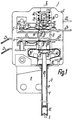
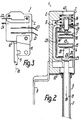
- the temperature limiter 1 shown in FIGS. 1 to 3 has a housing cover 3 that can be opened on its front side and closed with a plate-shaped flat cover Housing 2 made of insulation material, in which a circuit breaker 5 and a signal switch 4 in the form of snap-action switches of essentially the same design are arranged directly adjacent to one another and one behind the other.
- a rod-shaped, rectilinear temperature sensor 6 is attached to the housing 2 serving as a base and essentially consists of an outer tube 7 consisting of metal and an inner rod 8 arranged in a contact-free manner therein.
- the inner rod 8 is supported within the housing 2 with its associated end on a freely resiliently suspended transmission member 9 and is at its other end against an adjusting member l2, which is adjustable and self-locking in the form of a stud screw in an internal thread in the associated end of the outer tube 7 is led.
- the two switches 4, 5 each have a strip-shaped switch carrier l3 or l4, which is approximately the same as a stamped and bent part and is each equipped with a snap spring formed by a leaf spring, which carries or forms a switching contact l7 at its free end.
- the two switch supports l3, l4, including their snap springs l5, l6, are arranged essentially mirror-symmetrically to a central plane perpendicular to the central axis l8 of the temperature sensor 6 or to the actuation direction in such a way that the snap springs l5, l6 on the sides facing away from one another Sides of the switch supports l3, l4.
- the switching contacts are assigned to counter-contacts l9, 20 which are fixed to the housing and are connected as a component of or electrically conductively to terminal lugs 2l, 22 projecting from the housing.
- Corresponding terminal lugs 23, 24 are also electrically conductively connected to the switch carriers l3, l4, or, in the case of the switch carrier l4, are formed in one piece therewith.
- the two connecting lugs 2l, 23 of the one switch 4 protrude from a narrow side of the housing 2, while the connecting lugs 22, 24 of the other switch 5 protrude from the opposite narrow side of the housing 2.
- the counter-contact l9 of the signal switch 4 is designed as a cutting-like contact tip, which directly, ie without a separate switching contact, cooperates in an electrically conductive manner with an end section of the associated snap spring l5.
- This counter contact l9 is expediently formed in one piece from sheet metal with the associated terminal lug 2l.
- the transmission member 9 is designed in the manner of a freely suspended, linearly movably mounted transmission rod as a U-shaped bracket or bridge, which in turn has U-sections both in the area of the bracket legs 25, 26 and in the area of the bracket crosspiece parallel to the temperature sensor 6 has directed U-legs, so that it can be made, for example, of relatively thin sheet metal and still has a very high strength.
- the bow crossbar 28 is located on the side of the switches 4, 5 facing away from the open housing side in a corresponding recess in the housing base, which merges into recesses for receiving the snap springs and contacts and from the suspension springs.
- the latter To support the inner rod 8 on the outside of the associated bracket leg 25, the latter carries a bolt-shaped intermediate member 29, the head of which rests between the U-legs 27 on the outside of the stirrup leg 25 and which passes through the stirrup leg 25 with a reduced-diameter shank section, this shank section with its free end an actuating member 30 lying in the central axis for the closer at the temperature sensor 6 lying signal switch 4 forms.
- the actuating element 30 is assigned a knob-shaped actuating point 3l, against which the actuating element 30 rests with its end face.
- actuating member 32 On the inside of the other stirrup leg 26 there is also an actuating member 32 which is formed by the associated end of an adjusting member 34 designed as an adjusting screw, which lies in the central axis 18 of the temperature sensor 6 and which projects outward in one piece with the stirrup leg 26 Internal thread sleeve 35 is adjustable with an external thread and is guided by self-locking.
- the actuating member 32 acts via an actuating point 33 of an intermediate member 36 on a knob-shaped actuating point 37, which is also provided between the clamping zones on the associated side of the snap spring 16.
- the intermediate members 29, 36 suitably consist of insulating material.
- the intermediate member 36 is mounted independently of the actuator 32 directly on the transmission member 9 in the actuating direction in a resilient manner in that it is arranged on a leg which projects freely between the actuator 32 and the actuating point 37 of an angular spring tab 38 fastened to the inside of the crosspiece 28 of the bracket.
- the spring 39 which is closer to the temperature sensor 6 and is designed as a bow-shaped leaf spring, is rigidly attached to the middle section of its cross bar 4l on the inside of the U crossbar of the bracket leg 25, for example by spot welding and penetrated by the actuator 30.
- the approximately U-shaped mutually curved bracket legs 42 of the spring 39 are so biased inserted into the housing 2 that they are precisely secured in their position on the one hand by multiple contact on surfaces lying at an angle and on the other hand are biased so that the bracket crossbar 4l even with release from the transmission member 9 still has a certain bias towards the other end of the transmission member 9.
- the other, much stronger spring 40 is designed as a helical compression spring lying in the central axis 18, which surrounds the adjusting member 34 and is supported on the one hand between the U-legs on the bracket leg 26 and on the other hand on an opposite inner surface of the housing 2.
- This area is penetrated by an opening 43 provided in the associated housing wall facing away from the temperature sensor 6, which connects to the housing cover 3 and through which the adjusting member 34 is accessible from the outside at any time for readjustment.
- the spring 40 presses the transmission member 9 or the spherically curved end face of the intermediate member 29 against the inner rod 8 and acts together with the spring 39 as a linear guide for the transmission member 9.
- the switch supports l3, l4 and the counterparts l9, 20 carrying, made of sheet metal fasteners, the flange plate l0, the springs 39, 40 and the transmission member 9 are inserted from the open side of the housing 2 after removal of the housing cover 3 in corresponding openings and thereby essentially aligned and secured in position, so that essentially no separate fastening parts are required.
- a web-shaped projection of the housing which extends essentially up to the housing cover 3 and against which these ends of the switch carriers l3, l4 abut, these ends serving to support the snap springs when the switches are open.
- the lying on the other side of the transmission member 9 areas of the switch carrier l3, l4 are each provided with a protruding to the other switch carrier profile 45, which engages in a corresponding recess in the associated slot of the housing 2, so that the respective switch carrier also in its longitudinal direction is precisely aligned.
- the housing 2 For the positive reception of a profile edge of the flange plate 10 lying adjacent to the temperature sensor 6, the housing 2 has a correspondingly profiled holding slot 44.
- the flange plate 10 is provided with a rivet or the like. attached to the housing 2.
- the inner rod 8 which is designed as a pressure rod, is shortened relative to the outer tube 7, so that the signal switch 4 according to FIG. 1 closes, for example at a temperature of about 60 °, and thereby switches on an optical or similar hot indicator which indicates that the cooking unit o . Like. must not be touched.
- the actuator 30 lifts off the actuation point 3l and finally the circuit breaker 5 is opened at the set maximum temperature and the heating is thereby switched off.
- the two switching points are adjusted via the adjusting elements 12, 34 located in a central axis 18.
Landscapes
- Physics & Mathematics (AREA)
- Thermal Sciences (AREA)
- Thermally Actuated Switches (AREA)
- Inorganic Insulating Materials (AREA)
- Control Of Motors That Do Not Use Commutators (AREA)
- Glass Compositions (AREA)
- Control Of Resistance Heating (AREA)
- Pharmaceuticals Containing Other Organic And Inorganic Compounds (AREA)
- Transition And Organic Metals Composition Catalysts For Addition Polymerization (AREA)
- Control Of Temperature (AREA)
Claims (10)
- Limiteur de température (1) pour un chauffage, en particulier une unité de cuisson à vitrocéramique, comprenant un palpeur de température (6) essentiellement en forme de tige, possédant un tube externe (7) et une tige interne (8) située à l'intérieur de ce tube et ayant un coefficient de dilatation différent, qui est prévu pour commander un interrupteur de signalisation (4) placé dans un socle (2) et un interrupteur de puissance (5), placé également dans le socle (2), pour couper le chauffage à une température maximale préfixée, avec un élément de transmission (9) qui fait suite à l'extrémité côté socle de la tige interne (8) et porte des éléments de commande (30, 32) attaquant des points de commande (31, 37) des deux interrupteurs (4, 5) situés dans le prolongement axial de la tige interne (8), caractérisé en ce que l'un au moins des éléments de commande (32) est relié à un dispositif d'ajustement prévu sur l'élément de transmission (9) et au moyen duquel on peut varier l'écartement mutuel des éléments de commande (30, 32).
- Limiteur de température selon la revendication 1, caractérisé en ce qu'un élément de commande (32) est formé directement par un élément d'ajustement (34) situé à peu près dans le prolongement de la tige interne (8), en particulier par une vis d'ajustement.
- Limiteur de température selon la revendication 1 ou 2, caractérisé en ce que le dispositif d'ajustement est disposé sur l'élément de commande (32) éloigné de la tige interne (8).
- Limiteur de température selon une des revendications 1 à 3, caractérisé en ce que l'élément de transmission (9), déplaçable essentiellement en ligne droite, est librement suspendu élastiquement, sans contact, en particulier vis-à-vis du socle (2).
- Limiteur de température selon une des revendications 1 à 4, caractérisé en ce que l'élément de transmission (9) est monté entre deux ressorts (39, 40) agissant en sens contraire, constitués en particulier par des ressorts de compression attaquant directement l'élément de transmission (9) et dont de préférence au moins un ressort (39, 40) et en particulier les deux, est ou sont situé(s) chacun dans la zone d'une extrémité de l'élément de transmission (9), de préférence le ressort (40) éloigné de la tige interne (8) étant appuyé sur une face extrême correspondante de l'élément de transmission (9) et réalisé notamment comme un ressort hélicoïdal entourant l'élément d'ajustement (34) et/ou le ressort (39) situé plus près de la tige interne (8) étant réalisé comme un ressort plat, en particulier en forme d'étrier, qui est conçu de préférence comme un guide pour l'élément de transmission (9).
- Limiteur de température selon une des revendications précédentes, caractérisé en ce que l'élément de transmission (9) est réalisé comme un pont, notamment sous la forme d'un archet, qui contourne les interrupteurs (4, 5) et ne les traverse pas et/ou que les éléments de commande (30, 32) sont disposés en opposition ou en étant dirigés l'un vers l'autre sur l'élément de transmission (9), en particulier sur les branches (25, 26) de l'archet, de préférence le ressort (39) situé plus près de la tige interne (8) étant fixé, notamment par la base (41) de sa forme en étrier, au côté de l'élément de transmission (9) éloigné de la tige interne (8), ou étant traversé par l'élément de commande (30) correspondant.
- Limiteur de température selon une des revendications précédentes, caractérisé en ce qu'un élément intermédiaire (36) isolant est placé entre un élément de commande (32) disposé de façon ajustable sur l'élément de transmission (9) et le point de commande (37) de l'interrupteur (5) correspondant, élément intermédiaire qui est fixé indépendamment de l'élément de commande (32) à l'élément de transmission (9) de manière à faire saillie librement, en particulier au moyen d'un support élastique (38) ou analogue et/ou qu'au moins un point de commande (31, 37) est prévu directement sur un ressort à mouvement brusque (15, 16) de l'interrupteur (4, 5) associé, réalisé comme un interrupteur instantané, les deux interrupteurs (4, 5) étant munis en particulier de ressorts à mouvement brusque (15, 16) montés en opposition.
- Limiteur de température selon une des revendications précédentes, caractérisé en ce que les interrupteurs (4, 5) et en particulier leurs ressorts à mouvement brusque (15, 16), possèdent différents écarts entre les points de commutation, l'écart entre les points de commutation de l'interrupteur de signalisation (4) étant de préférence nettement plus petit.
- Limiteur de température selon une des revendications précédentes, caractérisé en ce que l'interrupteur (5) coordonné à l'élément de commande (32) disposé ajustable sur l'élément de transmission (9) et/ou éloigné de la tige interne (8), est prévu comme interrupteur de puissance.
- Limiteur de température selon une des revendications précédentes, caractérisé en ce que la tige interne (8) est agencée pour agir comme une tige de pression et est appuyée, de préférence dans la région de son extrémité éloignée du socle, sur un élément d'ajustement (12).
Priority Applications (1)
| Application Number | Priority Date | Filing Date | Title |
|---|---|---|---|
| AT86115496T ATE65343T1 (de) | 1985-11-14 | 1986-11-08 | Temperaturbegrenzer. |
Applications Claiming Priority (2)
| Application Number | Priority Date | Filing Date | Title |
|---|---|---|---|
| DE19853540414 DE3540414A1 (de) | 1985-11-14 | 1985-11-14 | Temperaturbegrenzer |
| DE3540414 | 1985-11-14 |
Publications (3)
| Publication Number | Publication Date |
|---|---|
| EP0225490A2 EP0225490A2 (fr) | 1987-06-16 |
| EP0225490A3 EP0225490A3 (en) | 1988-09-14 |
| EP0225490B1 true EP0225490B1 (fr) | 1991-07-17 |
Family
ID=6285988
Family Applications (1)
| Application Number | Title | Priority Date | Filing Date |
|---|---|---|---|
| EP86115496A Expired - Lifetime EP0225490B1 (fr) | 1985-11-14 | 1986-11-08 | Limiteur de température |
Country Status (7)
| Country | Link |
|---|---|
| US (1) | US4695816A (fr) |
| EP (1) | EP0225490B1 (fr) |
| JP (1) | JPH0775137B2 (fr) |
| AT (1) | ATE65343T1 (fr) |
| DE (2) | DE3540414A1 (fr) |
| ES (1) | ES2022804B3 (fr) |
| YU (1) | YU193186A (fr) |
Families Citing this family (21)
| Publication number | Priority date | Publication date | Assignee | Title |
|---|---|---|---|---|
| EP0252523A3 (fr) * | 1986-07-11 | 1990-02-07 | Nibex Company, Ltd. | Capteur de température |
| DE3705260A1 (de) * | 1987-02-19 | 1988-09-01 | Ego Elektro Blanc & Fischer | Temperaturbegrenzer |
| US4908596A (en) * | 1989-02-17 | 1990-03-13 | Therm-O-Disc, Incorporated | Thermostat assembly |
| DE3913289A1 (de) * | 1989-04-22 | 1990-10-25 | Ego Elektro Blanc & Fischer | Temperatur-schaltgeraet |
| DE3913288A1 (de) * | 1989-04-22 | 1990-10-25 | Ego Elektro Blanc & Fischer | Temperatur-schaltgeraet |
| DE4029351A1 (de) * | 1990-09-15 | 1992-03-19 | Ego Elektro Blanc & Fischer | Temperaturfuehler |
| DE4138814C2 (de) * | 1991-11-26 | 2002-08-01 | Ego Elektro Geraetebau Gmbh | Temperatur-Schaltgerät |
| DE4138815A1 (de) * | 1991-11-26 | 1993-05-27 | Ego Elektro Blanc & Fischer | Sockel fuer eine elektromechanische funktionseinheit |
| US7008783B1 (en) | 1992-09-22 | 2006-03-07 | Maruha Corporation | Gene encoding chondroitinase ABC and uses therefor |
| AT401114B (de) * | 1993-12-03 | 1996-06-25 | Electrovac | Temperaturregler |
| DE19745096C2 (de) * | 1997-10-11 | 2001-11-22 | Diehl Ako Stiftung Gmbh & Co | Schalteinrichtung für eine Kochzonenheizung |
| DE19846513A1 (de) | 1998-10-09 | 2000-04-13 | Ego Elektro Geraetebau Gmbh | Schalteinrichtung für eine elektrische Heizeinrichtung |
| US6267602B1 (en) * | 1999-11-02 | 2001-07-31 | Kinetic Group L.L.C. | Detachable power supply apparatus |
| US6250931B1 (en) * | 1999-11-02 | 2001-06-26 | Kinetic Group L.L.C. | Detachable power supply apparatus |
| ATE371256T1 (de) * | 2001-01-10 | 2007-09-15 | Electrovac | Temperaturbegrenzer |
| AT409680B (de) | 2001-04-17 | 2002-10-25 | Electrovac | Temperaturbegrenzer |
| AT411554B (de) * | 2002-02-25 | 2004-02-25 | Electrovac | Temperaturfühler |
| GB0717051D0 (en) * | 2007-09-01 | 2007-10-17 | Ceramaspeed Ltd | Temperature sensor |
| CN101216533B (zh) * | 2008-01-04 | 2010-06-02 | 广东格兰仕集团有限公司 | 热切断器的自动检测设备及其工作方法 |
| DE102009038960A1 (de) * | 2009-08-19 | 2011-02-24 | E.G.O. Elektro-Gerätebau GmbH | Temperaturfühler und Verfahren zur Justierung eines solchen Temperaturfühlers |
| WO2016183889A1 (fr) * | 2015-05-15 | 2016-11-24 | 深圳市鑫富达电器有限公司 | Plaque chauffante à régulation de température, isolée thermiquement |
Family Cites Families (16)
| Publication number | Priority date | Publication date | Assignee | Title |
|---|---|---|---|---|
| US1806651A (en) * | 1931-05-26 | Marine pumping system | ||
| CH112032A (de) * | 1924-08-29 | 1925-10-16 | Zbinden Emil | Kontaktvorrichtung an einer elektrischen Temperaturreguliereinrichtung. |
| US1902451A (en) * | 1929-04-19 | 1933-03-21 | Honeywell Regulator Co | Thermostatic switch for use with heaters |
| CH208830A (de) * | 1939-04-19 | 1940-02-29 | Landis & Gyr Ag | Elektrischer Schalter mit bei kleinem Weg ohne Verwendung eines Magneten kippendem, beweglichem Kontaktglied. |
| BE460225A (fr) * | 1944-10-24 | |||
| FR1009300A (fr) * | 1949-06-08 | 1952-05-27 | Thermostat | |
| US3100758A (en) * | 1959-12-31 | 1963-08-13 | Continental Can Co | Vinyl halide copolymers with oxirane-containing side groups having improved heat stability |
| GB1238286A (fr) * | 1967-11-02 | 1971-07-07 | ||
| GB1277848A (en) * | 1970-04-16 | 1972-06-14 | Ranco Controls Ltd | Thermostat |
| US3906424A (en) * | 1974-05-13 | 1975-09-16 | Therm O Disc Inc | Cooking range and control therefor |
| DE2748109C2 (de) * | 1977-10-27 | 1982-04-15 | Licentia Patent-Verwaltungs-Gmbh, 6000 Frankfurt | Elektrokochgerät |
| DE2839161A1 (de) * | 1978-09-08 | 1980-03-20 | Ego Regeltech | Temperaturbegrenzer fuer eine glaskeramik-kocheinheit |
| DE3100758A1 (de) * | 1981-01-13 | 1982-09-02 | Ako Werke Gmbh & Co | Schalteinrichtung |
| AT386714B (de) * | 1983-07-07 | 1988-10-10 | Electrovac | Vorrichtung zur heissanzeige und zur regelung bzw. begrenzung der temperatur von strahlungsbzw. kontaktheizkoerpern von elektrischen kochgeraeten |
| DE3410442A1 (de) * | 1983-09-17 | 1985-09-26 | Ego Elektro Blanc & Fischer | Temperaturfuehler, insbesondere fuer einen temperaturbegrenzer fuer eine glaskeramik-kocheinheit |
| DE3333645A1 (de) * | 1983-09-17 | 1985-04-11 | E.G.O. Elektro-Geräte Blanc u. Fischer, 7519 Oberderdingen | Temperaturbegrenzer fuer eine glaskeramikkocheinheit |
-
1985
- 1985-11-14 DE DE19853540414 patent/DE3540414A1/de not_active Withdrawn
-
1986
- 1986-11-08 AT AT86115496T patent/ATE65343T1/de not_active IP Right Cessation
- 1986-11-08 EP EP86115496A patent/EP0225490B1/fr not_active Expired - Lifetime
- 1986-11-08 ES ES86115496T patent/ES2022804B3/es not_active Expired - Lifetime
- 1986-11-08 DE DE8686115496T patent/DE3680301D1/de not_active Expired - Lifetime
- 1986-11-13 YU YU01931/86A patent/YU193186A/xx unknown
- 1986-11-13 US US06/930,862 patent/US4695816A/en not_active Expired - Fee Related
- 1986-11-14 JP JP61269986A patent/JPH0775137B2/ja not_active Expired - Lifetime
Also Published As
| Publication number | Publication date |
|---|---|
| ES2022804B3 (es) | 1991-12-16 |
| JPS62165823A (ja) | 1987-07-22 |
| EP0225490A3 (en) | 1988-09-14 |
| ATE65343T1 (de) | 1991-08-15 |
| DE3540414A1 (de) | 1987-05-21 |
| EP0225490A2 (fr) | 1987-06-16 |
| YU193186A (en) | 1988-10-31 |
| JPH0775137B2 (ja) | 1995-08-09 |
| US4695816A (en) | 1987-09-22 |
| DE3680301D1 (de) | 1991-08-22 |
Similar Documents
| Publication | Publication Date | Title |
|---|---|---|
| EP0225490B1 (fr) | Limiteur de température | |
| EP0279368B1 (fr) | Limiteur de température | |
| EP0141923B1 (fr) | Limiteur de température pour plaques de cuisson en vitro-céramique | |
| DE4138817A1 (de) | Temperaturerfassungs-geraet | |
| EP0394693B1 (fr) | Appareil de commutation de température | |
| EP0563775A1 (fr) | Disjoncteur de protection commandé par bimétal | |
| EP0347592B1 (fr) | Dispositif de verrouillage de porte pour appareils électriques | |
| DE3526785C1 (de) | Druckknopfbetaetigter UEberstromschutzschalter | |
| DE3333645A1 (de) | Temperaturbegrenzer fuer eine glaskeramikkocheinheit | |
| WO2003065398A1 (fr) | Appareil de distribution electrique | |
| DE1924701C3 (de) | Vorrichtung zur Betätigung eines Schalters mit einem zwei in Abstand voneinander befindliche Schenkel aufweisenden Bimetallblech | |
| EP0377169B1 (fr) | Appareil interrupteur | |
| DE2511223C2 (de) | Druckknopfbetätigter Überstromschalter mit thermischer Auslösung | |
| DE2502579C2 (de) | Druckknopfbetaetigter ueberstromschalter mit thermischer ausloesung | |
| DE3604021A1 (de) | Thermostat | |
| DE1914687B2 (de) | Schutzschalter | |
| DE2724527A1 (de) | Temperaturregler | |
| DE10016141C1 (de) | Thermisch gesteuerte elektrische Schaltvorrichtung | |
| DE3324253A1 (de) | Tastenschalter | |
| DE1814513A1 (de) | Sicherungsvorrichtung an elektrischen Geraeten | |
| DE2513494A1 (de) | Temperaturschutzschalter fuer rohrheizkoerper | |
| DE4138814C2 (de) | Temperatur-Schaltgerät | |
| EP0481355A2 (fr) | Appareil interrupteur comprenant un dispositif pour commander une influence charactéristiq ambiante | |
| EP0043406B1 (fr) | Elément interrupteur de protection pour être ajouté à un appareil interrupteur construit comme interrupteur rotatif | |
| DE2442873C2 (de) | Leistungssteuergerät für Elektrokoch- oder wärmegeräte |
Legal Events
| Date | Code | Title | Description |
|---|---|---|---|
| PUAI | Public reference made under article 153(3) epc to a published international application that has entered the european phase |
Free format text: ORIGINAL CODE: 0009012 |
|
| AK | Designated contracting states |
Kind code of ref document: A2 Designated state(s): AT CH DE ES FR GB IT LI SE |
|
| PUAL | Search report despatched |
Free format text: ORIGINAL CODE: 0009013 |
|
| AK | Designated contracting states |
Kind code of ref document: A3 Designated state(s): AT CH DE ES FR GB IT LI SE |
|
| 17P | Request for examination filed |
Effective date: 19881228 |
|
| 17Q | First examination report despatched |
Effective date: 19900924 |
|
| GRAA | (expected) grant |
Free format text: ORIGINAL CODE: 0009210 |
|
| AK | Designated contracting states |
Kind code of ref document: B1 Designated state(s): AT CH DE ES FR GB IT LI SE |
|
| REF | Corresponds to: |
Ref document number: 65343 Country of ref document: AT Date of ref document: 19910815 Kind code of ref document: T |
|
| REF | Corresponds to: |
Ref document number: 3680301 Country of ref document: DE Date of ref document: 19910822 |
|
| ITF | It: translation for a ep patent filed | ||
| GBT | Gb: translation of ep patent filed (gb section 77(6)(a)/1977) | ||
| ET | Fr: translation filed | ||
| PLBE | No opposition filed within time limit |
Free format text: ORIGINAL CODE: 0009261 |
|
| STAA | Information on the status of an ep patent application or granted ep patent |
Free format text: STATUS: NO OPPOSITION FILED WITHIN TIME LIMIT |
|
| 26N | No opposition filed | ||
| PGFP | Annual fee paid to national office [announced via postgrant information from national office to epo] |
Ref country code: GB Payment date: 19921028 Year of fee payment: 7 Ref country code: AT Payment date: 19921028 Year of fee payment: 7 |
|
| PGFP | Annual fee paid to national office [announced via postgrant information from national office to epo] |
Ref country code: ES Payment date: 19921030 Year of fee payment: 7 |
|
| PGFP | Annual fee paid to national office [announced via postgrant information from national office to epo] |
Ref country code: FR Payment date: 19921116 Year of fee payment: 7 |
|
| PGFP | Annual fee paid to national office [announced via postgrant information from national office to epo] |
Ref country code: SE Payment date: 19921125 Year of fee payment: 7 |
|
| PGFP | Annual fee paid to national office [announced via postgrant information from national office to epo] |
Ref country code: CH Payment date: 19921218 Year of fee payment: 7 |
|
| PGFP | Annual fee paid to national office [announced via postgrant information from national office to epo] |
Ref country code: DE Payment date: 19930126 Year of fee payment: 7 |
|
| PG25 | Lapsed in a contracting state [announced via postgrant information from national office to epo] |
Ref country code: GB Effective date: 19931108 Ref country code: AT Effective date: 19931108 |
|
| PG25 | Lapsed in a contracting state [announced via postgrant information from national office to epo] |
Ref country code: SE Effective date: 19931109 |
|
| PG25 | Lapsed in a contracting state [announced via postgrant information from national office to epo] |
Ref country code: ES Free format text: LAPSE BECAUSE OF EXPIRATION OF PROTECTION Effective date: 19931110 |
|
| PG25 | Lapsed in a contracting state [announced via postgrant information from national office to epo] |
Ref country code: LI Effective date: 19931130 Ref country code: CH Effective date: 19931130 |
|
| GBPC | Gb: european patent ceased through non-payment of renewal fee |
Effective date: 19931108 |
|
| PG25 | Lapsed in a contracting state [announced via postgrant information from national office to epo] |
Ref country code: FR Effective date: 19940729 |
|
| REG | Reference to a national code |
Ref country code: CH Ref legal event code: PL |
|
| PG25 | Lapsed in a contracting state [announced via postgrant information from national office to epo] |
Ref country code: DE Effective date: 19940802 |
|
| REG | Reference to a national code |
Ref country code: FR Ref legal event code: ST |
|
| EUG | Se: european patent has lapsed |
Ref document number: 86115496.1 Effective date: 19940610 |
|
| REG | Reference to a national code |
Ref country code: ES Ref legal event code: FD2A Effective date: 20010301 |
|
| PG25 | Lapsed in a contracting state [announced via postgrant information from national office to epo] |
Ref country code: IT Free format text: LAPSE BECAUSE OF NON-PAYMENT OF DUE FEES;WARNING: LAPSES OF ITALIAN PATENTS WITH EFFECTIVE DATE BEFORE 2007 MAY HAVE OCCURRED AT ANY TIME BEFORE 2007. THE CORRECT EFFECTIVE DATE MAY BE DIFFERENT FROM THE ONE RECORDED. Effective date: 20051108 |