EP0225517B1 - Machine à tisser et procédé pour insérer un appareil de commande sur le métier à tisser - Google Patents
Machine à tisser et procédé pour insérer un appareil de commande sur le métier à tisser Download PDFInfo
- Publication number
- EP0225517B1 EP0225517B1 EP86116050A EP86116050A EP0225517B1 EP 0225517 B1 EP0225517 B1 EP 0225517B1 EP 86116050 A EP86116050 A EP 86116050A EP 86116050 A EP86116050 A EP 86116050A EP 0225517 B1 EP0225517 B1 EP 0225517B1
- Authority
- EP
- European Patent Office
- Prior art keywords
- control unit
- loom
- guide member
- loom according
- transverse bearer
- Prior art date
- Legal status (The legal status is an assumption and is not a legal conclusion. Google has not performed a legal analysis and makes no representation as to the accuracy of the status listed.)
- Expired - Lifetime
Links
- 238000000034 method Methods 0.000 title claims description 5
- 239000004744 fabric Substances 0.000 claims description 6
- 125000006850 spacer group Chemical group 0.000 claims description 6
- 238000009941 weaving Methods 0.000 description 26
- 238000009434 installation Methods 0.000 description 5
- 239000002184 metal Substances 0.000 description 2
- 230000000295 complement effect Effects 0.000 description 1
- 230000007547 defect Effects 0.000 description 1
- 238000001514 detection method Methods 0.000 description 1
Images


Classifications
-
- D—TEXTILES; PAPER
- D03—WEAVING
- D03D—WOVEN FABRICS; METHODS OF WEAVING; LOOMS
- D03D49/00—Details or constructional features not specially adapted for looms of a particular type
- D03D49/02—Construction of loom framework
Definitions
- the invention relates to a weaving machine with a drive device and a cross member running over the weaving width of the weaving machine, on which at least one electrical or electronic switching unit connected to the drive device is arranged, which contains control elements in particular for starting, stopping and controlling the weaving machine.
- the invention further relates to a method for attaching a switching unit of the type mentioned to the weaving machine.
- the invention has for its object to provide a weaving machine, particularly improved in this regard, and a correspondingly simplified installation method, which ensures reliable positioning of the switching unit and its connection to the drive device in a shorter assembly time than previous designs.
- the cross member is provided with at least one rail-like guide part for the switching unit, and in that the switching unit has at least one holding part which can be moved together with the guide part, and in that the guide part has means for Detection of the switching unit are assigned.
- the arrangement according to the invention permits the use of ready-to-install, particularly simply constructed and correspondingly inexpensive switching units (“prints”) with integrated operating elements, as a result of which a pre-assembly of the switching units, which was required in previous designs, is eliminated.
- the switching units can rather be attached directly to the guide part, moved in a simple manner into the predetermined operating position and locked. This enables considerable cost and labor savings.
- the method according to the invention for attaching at least one switching unit to the weaving machine consists in that the switching unit is brought together with the guide part from one end and is moved at least over part of its longitudinal extent into a predetermined operating position, and is then determined in this operating position and in a position with the Drive device connected control system is connected, and that the guide part is attached to a cross member of the loom.
- a rational, in particular screwless attachment of the switching unit or several switching units can be achieved in a variable operating position.
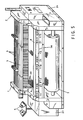
- I contains a machine frame with two side cheeks I and 2 and two cross members 3 and 3a connecting them.
- a number of heald frames 4 for guiding warp threads 30 and for forming a shed are arranged between the side cheeks I and 2.
- a weft thread is drawn off from a weft spool 5 arranged outside the shed, in a manner not shown, for example by compressed air or a projectile or by gripper, is inserted into the shed and struck in the tip of the shed on the fabric 6 starting there.
- the fabric 6 is wound in a known manner onto a fabric tree 7 arranged between the side cheeks 1, 2.
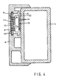
- the cross member 3 extends essentially above the shed over the weaving width of the weaving machine, while the cross member 3 a, as a so-called “chest cross member”, connects the end portions of the side cheeks 1 and 2 on the goods side. 4, the cross member 3 can have a square hollow profile.
- two mutually opposite guide grooves 9 and 10 are formed in the holding rail 8, which extend substantially over the entire length of the cross member 3.
- Arranged in the guide grooves 9 and 10 are three plate-shaped switching units II, Ila, Ilb which are distributed over the longitudinal extent of the cross member 3 and which are kept at a distance from one another by corresponding plate-shaped spacers 12.
- the switching units II, 11a, 11b each contain a printed circuit board 13 with integrated switching connections and switches 14, 15, 16, 17, 18 and 19, which act as a break switch can be formed, which are not or only to a very small extent over the projecting surrounding installation area of the relevant circuit board 13.
- the circuit boards 13 and the spacers 12 are each slidably guided parallel to the longitudinal extension of the cross member 3 with two holding parts formed on their lateral edges in the guide grooves 9 and 10.
- the installation positions of the switches 14 to 19 are provided with correspondingly arranged operating openings 21 which make the switches 14 to 19 in question accessible.
- At least one of the switching units II, IIa, Ilb is essentially within easy reach of each section of the weaving width for the operator to start or stop the weaving machine, so that the removal of fabric defects, in particular warp or weft breaks, correspondingly short downtimes of the weaving machine are required.
- the switch 14 is used to start the weaving machine
- the switches 15 and 16 are used to switch on a stepwise rewinding or advancing of the weaving machine
- the switch 17 is used to synchronize the devices coupled to the weaving machine drive
- the switches 18 to switch off the weaving machine.
- the switch 19 can form part of a "two-hand lock" which must be actuated simultaneously with the switch 14 or 15 or 16 in order to release a locking of these switches 14, 15 and 16 provided for security reasons. This ensures that when the loom is switched on both hands of the operator remain outside the area of the moving parts of the loom.
- the circuit boards 13 can each be connected via a connecting plug 22 to a ribbon cable 23 which contains a plurality of control lines 24 which are connected to a control device 26 assigned to the drive device 27 of the weaving machine. Via the control lines 24, the drive device 27 can be influenced from each of the switching units II, Ila, Ilb.
- the ribbon cable 23 is guided through an installation space 25 provided between the cross member 3 and the printed circuit boards 13 and the spacers 12 and is connected to the control device 26 in a manner not shown.
- the switching units II, ILA, ILB and the spacers 12 can each be inserted at one end of the holding rail 8 removed from the cross member 3 into the two guide grooves 9 and 10 and shifted into the intended operating position, where they are determined by the spacers 12 and without further fastening means can be easily connected to the connector 22.
- the holding rail 8 can then be fastened to the cross member 3 in the operating position shown.
- the holding rail 8 remaining on the cross member 3 is equipped with the switching units II, Ila, Ilb.
- a corresponding holding rail 8 can also be attached to the cross member 3a designed as a crossbeam.
- the holding rail 8 can also contain more or less than three switching units, e.g. a single, centrally arranged switching unit, which can complement about two switching devices arranged on the side walls I and 2.
- a corresponding plastic profile can also be used for the holding rail.
- An embodiment is also possible in which the guideways for the switching units II, Ila, IIb are integrated in the crossmember and this is provided with operating openings 21 for the switches 14 to 19 or corresponding switching elements.
- the guideways for the switching units can also be formed on the outside of the cross member.
Landscapes
- Engineering & Computer Science (AREA)
- Textile Engineering (AREA)
- Looms (AREA)
Claims (8)
Applications Claiming Priority (2)
| Application Number | Priority Date | Filing Date | Title |
|---|---|---|---|
| CH5157/85A CH669223A5 (de) | 1985-12-04 | 1985-12-04 | Webmaschine und verfahren zur herstellung der webmaschine. |
| CH5157/85 | 1985-12-04 |
Publications (2)
| Publication Number | Publication Date |
|---|---|
| EP0225517A1 EP0225517A1 (fr) | 1987-06-16 |
| EP0225517B1 true EP0225517B1 (fr) | 1990-01-31 |
Family
ID=4288882
Family Applications (1)
| Application Number | Title | Priority Date | Filing Date |
|---|---|---|---|
| EP86116050A Expired - Lifetime EP0225517B1 (fr) | 1985-12-04 | 1986-11-20 | Machine à tisser et procédé pour insérer un appareil de commande sur le métier à tisser |
Country Status (6)
| Country | Link |
|---|---|
| US (1) | US4706714A (fr) |
| EP (1) | EP0225517B1 (fr) |
| JP (1) | JPH0788612B2 (fr) |
| BR (1) | BR8605952A (fr) |
| CH (1) | CH669223A5 (fr) |
| DE (1) | DE3668648D1 (fr) |
Families Citing this family (5)
| Publication number | Priority date | Publication date | Assignee | Title |
|---|---|---|---|---|
| BE1004304A3 (nl) * | 1989-07-06 | 1992-10-27 | Picanol Nv | Bevestiging voor afschermplaten bij weefmachines. |
| BE1010657A3 (nl) * | 1996-09-30 | 1998-11-03 | Picanol Nv | Weefmachine met minstens een schakeleenheid. |
| DE29905052U1 (de) | 1999-03-19 | 1999-06-02 | Lindauer Dornier Gmbh, 88131 Lindau | Einrichtung zur Bedienung von Webmaschinen |
| ITMI20070918A1 (it) * | 2007-05-07 | 2007-08-06 | Promatech Spa | Metodo automatico di controllo della velocita' di lavorazione di un telaio di tessitura al fine di ottimizzare la produttivita'. |
| CN107313162A (zh) * | 2017-08-22 | 2017-11-03 | 安徽华泰纺织有限公司 | 喷气织机游星纱齿轮隔离罩 |
Family Cites Families (5)
| Publication number | Priority date | Publication date | Assignee | Title |
|---|---|---|---|---|
| US3373773A (en) * | 1965-07-12 | 1968-03-19 | George H. Balentine Jr. | Loom |
| US3502115A (en) * | 1968-06-14 | 1970-03-24 | Burlington Industries Inc | Loom with inspection station and independently operable take-up mechanism |
| US4307275A (en) * | 1980-06-18 | 1981-12-22 | Oak Industries Inc. | Membrane switch construction and method for making same |
| US4421140A (en) * | 1981-12-17 | 1983-12-20 | Burlington Industries, Inc. | Dobby-activated loom motion lock-out device |
| US4624049A (en) * | 1985-05-23 | 1986-11-25 | Illinois Tool Works Inc. | Switch actuator assembly |
-
1985
- 1985-12-04 CH CH5157/85A patent/CH669223A5/de not_active IP Right Cessation
-
1986
- 1986-11-20 DE DE8686116050T patent/DE3668648D1/de not_active Expired - Lifetime
- 1986-11-20 EP EP86116050A patent/EP0225517B1/fr not_active Expired - Lifetime
- 1986-12-03 US US06/937,213 patent/US4706714A/en not_active Expired - Fee Related
- 1986-12-03 JP JP61288649A patent/JPH0788612B2/ja not_active Expired - Lifetime
- 1986-12-04 BR BR8605952A patent/BR8605952A/pt unknown
Also Published As
| Publication number | Publication date |
|---|---|
| US4706714A (en) | 1987-11-17 |
| BR8605952A (pt) | 1987-09-15 |
| JPH0788612B2 (ja) | 1995-09-27 |
| CH669223A5 (de) | 1989-02-28 |
| JPS62133152A (ja) | 1987-06-16 |
| EP0225517A1 (fr) | 1987-06-16 |
| DE3668648D1 (de) | 1990-03-08 |
Similar Documents
| Publication | Publication Date | Title |
|---|---|---|
| DE1925350A1 (de) | Klammer zur Montage von Apparaturen auf Lochplatten | |
| EP0225517A1 (fr) | Machine à tisser et procédé pour insérer un appareil de commande sur le métier à tisser | |
| DE2349466C3 (de) | Verfahren und Vorrichtung zum gleichzeitigen und getrennten Überwachen zweier unter einem kleinen Winkel zusammenlaufender Fäden einer schützenlosen Webmaschine | |
| EP0421370B1 (fr) | Palonnier pour machine Jacquard | |
| EP2397601A1 (fr) | Traverse pour un appareil ménager, groupe pour l'assemblage d'un appareil ménager et appareil ménager | |
| DE2635445A1 (de) | Vorrichtung zur waermeabfuehrung aus geraeten | |
| EP0239785B1 (fr) | Listeau de centrage pour l'enfichage sur une plaque murale de conducteurs pourvue de contacts auto-dénudants | |
| EP0565958A2 (fr) | Métier à tisser modulaire | |
| EP0194439A2 (fr) | Bloc de bornes de connexion en série | |
| DE4308566A1 (de) | Wandinstallationskanal | |
| DE19518220B4 (de) | Ausziehvorrichtung für einen Telekommunikationsgeräterahmen | |
| DE3214600A1 (de) | Zufuhreinrichtung fuer gegurtete elektronische bauelemente zu bestueckungsautomaten fuer leiterplatten oder dgl. | |
| DE4021972C2 (fr) | ||
| WO1997049270A1 (fr) | Chassis de montage de sous-ensembles enfichables pourvus de plaques frontales pouvant etre centrees | |
| DE102021133811B4 (de) | Kabelkanal für automatisierte Verdrahtung einer elektrischen Steuerungs- oder Schaltanlage | |
| DE2428882A1 (de) | Gedruckte leiterplatte fuer ein geraet der nachrichtentechnik, insbesondere einen fernsehempfaenger | |
| DE3112642C2 (de) | Rahmen für einschiebbare elektrische Baugruppen | |
| EP0052155B1 (fr) | Dispositif pour la détection des cassures de fils de chaîne dans un métier à tisser | |
| DE2845204C2 (de) | Textkarte für in Baugruppenträger einschiebbare Baugruppen | |
| EP0598163A1 (fr) | Dispositif pour recevoir les tiges de la ratierè et métier à tisser avec un tel dispositif | |
| DE2344808A1 (de) | Verdrahtungsrahmen fuer eine schalttafel | |
| DE3326212C2 (de) | Jacquardwebmaschine | |
| DE2036506C3 (de) | Verdrahtung zur schaltungsmäßigen Verbindung mehrerer parallel nebeneinander angeordneter Platten sowie Verfahren zur Herstellung der Verdrahtung | |
| DE2348492C3 (de) | Zieheinrichtung für Steckbaugruppen | |
| DE3243286A1 (de) | Vorrichtung zur fuehrung eines farbbandes in einem zeilendrucker |
Legal Events
| Date | Code | Title | Description |
|---|---|---|---|
| PUAI | Public reference made under article 153(3) epc to a published international application that has entered the european phase |
Free format text: ORIGINAL CODE: 0009012 |
|
| AK | Designated contracting states |
Kind code of ref document: A1 Designated state(s): BE DE FR IT |
|
| 17P | Request for examination filed |
Effective date: 19871114 |
|
| 17Q | First examination report despatched |
Effective date: 19890616 |
|
| GRAA | (expected) grant |
Free format text: ORIGINAL CODE: 0009210 |
|
| ITF | It: translation for a ep patent filed | ||
| AK | Designated contracting states |
Kind code of ref document: B1 Designated state(s): BE DE FR IT |
|
| REF | Corresponds to: |
Ref document number: 3668648 Country of ref document: DE Date of ref document: 19900308 |
|
| ET | Fr: translation filed | ||
| PLBE | No opposition filed within time limit |
Free format text: ORIGINAL CODE: 0009261 |
|
| STAA | Information on the status of an ep patent application or granted ep patent |
Free format text: STATUS: NO OPPOSITION FILED WITHIN TIME LIMIT |
|
| 26N | No opposition filed | ||
| ITTA | It: last paid annual fee | ||
| PGFP | Annual fee paid to national office [announced via postgrant information from national office to epo] |
Ref country code: FR Payment date: 19931018 Year of fee payment: 8 |
|
| PGFP | Annual fee paid to national office [announced via postgrant information from national office to epo] |
Ref country code: DE Payment date: 19941014 Year of fee payment: 9 |
|
| PGFP | Annual fee paid to national office [announced via postgrant information from national office to epo] |
Ref country code: BE Payment date: 19941018 Year of fee payment: 9 |
|
| PG25 | Lapsed in a contracting state [announced via postgrant information from national office to epo] |
Ref country code: FR Effective date: 19950731 |
|
| REG | Reference to a national code |
Ref country code: FR Ref legal event code: ST |
|
| PG25 | Lapsed in a contracting state [announced via postgrant information from national office to epo] |
Ref country code: BE Effective date: 19951130 |
|
| BERE | Be: lapsed |
Owner name: GEBRUDER SULZER A.G. Effective date: 19951130 |
|
| PG25 | Lapsed in a contracting state [announced via postgrant information from national office to epo] |
Ref country code: DE Effective date: 19960801 |
|
| PG25 | Lapsed in a contracting state [announced via postgrant information from national office to epo] |
Ref country code: IT Free format text: LAPSE BECAUSE OF NON-PAYMENT OF DUE FEES;WARNING: LAPSES OF ITALIAN PATENTS WITH EFFECTIVE DATE BEFORE 2007 MAY HAVE OCCURRED AT ANY TIME BEFORE 2007. THE CORRECT EFFECTIVE DATE MAY BE DIFFERENT FROM THE ONE RECORDED. Effective date: 20051120 |